Loading ...
Loading ...
Loading ...
16
|
INSTALLATION / USE & CARE
WARNING
NEVER CONNECT A GAS LINE DIRECTLY TO THE GRILL. A PRESSURE REGULATOR MUST BE INSTALLED ON ALL GAS EQUIP
-
MENT. ALL LOCAL CODES REQUIRE THAT THE PRESSURE REGULATOR SUPPLIED WITH YOUR GRILL IS USED. REMOVING OR
FAILING T
O
IN
S
TALL THE PRE
SS
URE REGULAT
O
R
C
AN RE
S
ULT IN FIRE AND
S
ERI
O
U
S
PER
SO
NAL INJURY AND WILL V
O
ID THE
WA
RR
ANTY
.
The grill is factory set to use either propane (LP) or natural gas
(NAT). It is critical that the gas you use matches that which the
grill was set up for. You can verify that by checking the rating
plate.
The Rating plate lists serial numbers, model numbers and gas type. This
one is underneath the drip tray.
The rating plate is located in one or more of the following
places:
• Attached to the underside of the drip tray
• On the heat shield behind the front panel
Ensure that the gas supplied meets with the minimum pressure
requirements. Do not operate the grill on any gas other than
that for which the grill has been set.
Fuel WC Max Inlet WC Min Under
Full Load
Nat Gas 7 in 4 in
LP 14 in 11 in
Water Column Requirements
Both the regulator and the manifold ori ces have been tuned
for the type of gas speci ed on the rating plate.
Converting to a di erent type of gas requires a conversion kit,
available from your dealer and must be installed by a quali ed
technician.
Installation must conform with local codes or, in the absence
of local codes, with either the National Fuel Gas Code, ANSI
Z223.1/NFPA 54, Natural Gas and propane Installation Code,
CSA B149.1, or Propane Storage and Handling Code, B149.2, in
Canada.Canadian installations must conform to CGA-B149.1/.2
natural gas/propane installation code. (Canada)
NATURAL GAS
Viking Range, LLC recommends that only quali ed professionals
perform the required plumbing on this product.
To ensure satisfactory performance, the gas supply line must be
sized to accommodate the total BTU requirements of all the gas-
red equipment that will be connected to that line.
In no case should pipe less than 3/4” inside diameter or 1” out-
side diameter ever be used to connect this product.
• Calculate the total BTU output of all equipment and refer to
“INDEX: Gas Supply Line Runs” for allowable run distances for
¾ inch pipe. Failure to meet these minimum requirements
may reduce performance of the grill and any other appliances
running on that supply line.
• Always keep supply line runs as short as possible. (See INDEX:
“BTU Output” for speci c model outputs)
• A gas shut-o valve must be installed in an easily accessible
location by a quali ed plumber.
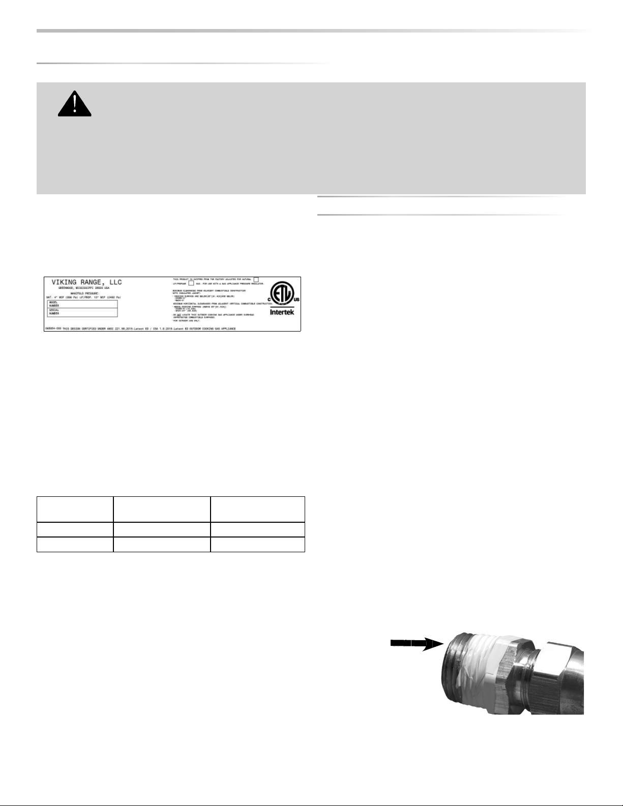
• Keep threading compound o of the rst two pipe threads to
avoid having any small pieces of compound break loose and
clog a burner valve or ori ce. Do not use threading compound
on any are ttings.
For built-in installations, it is recommended that any exible
pipe used be kept as short as possible. (See INDEX: “Gas Connec-
tions” for typical permanent hook up.)
GA
S
CO
NNE
C
TI
O
N
S
Keep last two threads
reads
cl
e
an
Loading ...
Loading ...
Loading ...