Loading ...
Loading ...
Loading ...
MKF / MKFT (E5) 06/2020 page 121/176
20. Zero-voltage switching outputs via operation lines
The chambers are regularly equipped with four zero-voltage switching outputs (DIN sockets (7) and (8)
located in the lateral control panel).
The operation lines serve to switch any device connected to the zero-voltage relay output. They can be
programmed On/Off in Fixed value and program modes.
Connection for operation lines “Switching output 1” and “Switching output 2” occurs via DIN socket (7),
connection for operation lines “Switching output 3” and “Switching output 4” via DIN socket (8) in the lat-
eral control panel:
OUTPUT TRACK 1+2
24V/MAX.2,5A
OUTPUT TRACK 3+4
24V/MAX.2,5A
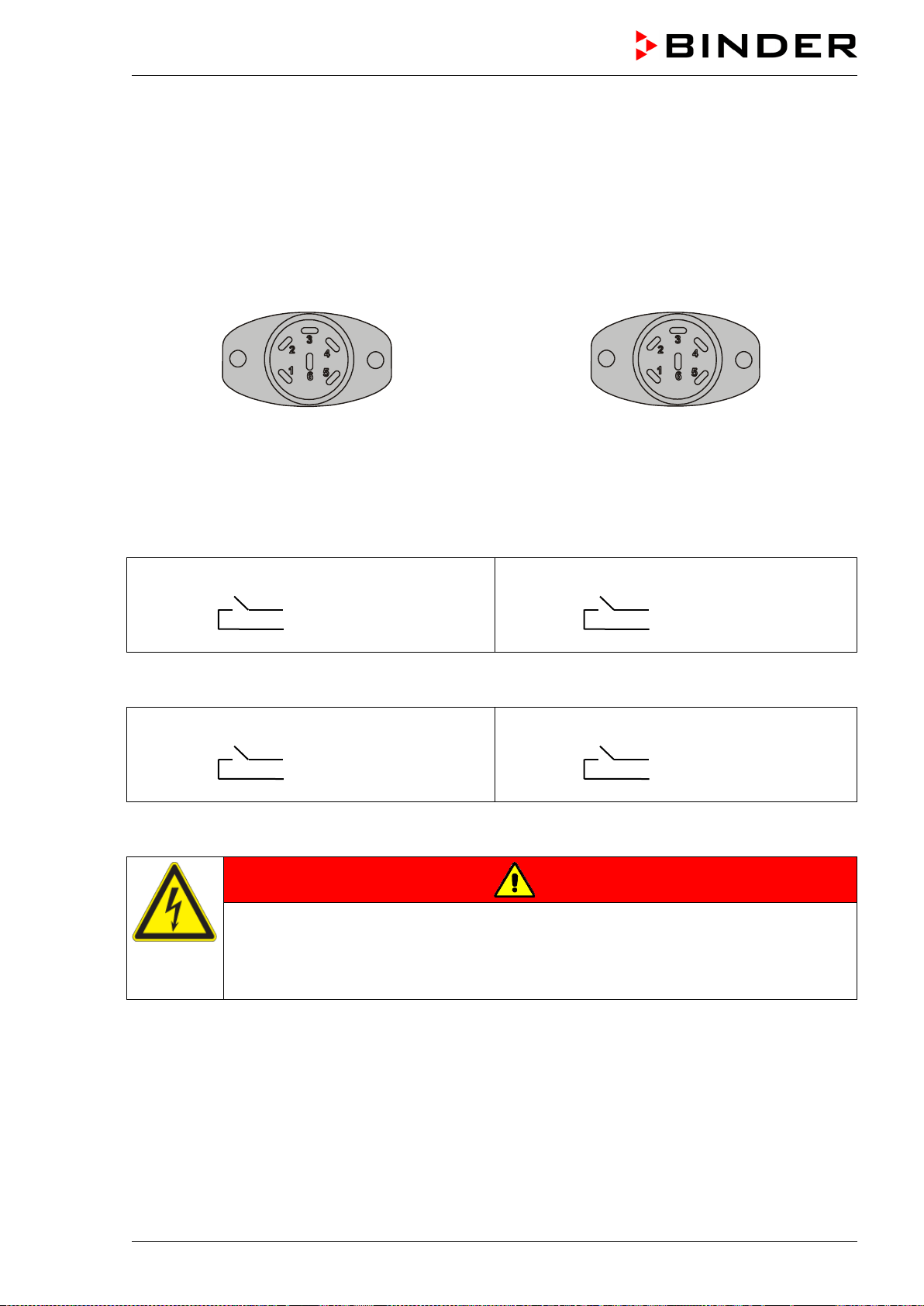
Figure 20: Pin configuration of DIN sockets (7) left and (8) right
DIN socket (7):
Operation line “Switching output 1” Operation line “Switching output 2”
Pin 1: Pin
Pin 2: Make
Pin 4: Pin
Pin 5: Make
DIN socket (8):
Operation line “Switching output 3” Operation line “Switching output 4”
Pin 1: Pin
Pin 2: Make
Pin 4: Pin
Pin 5: Make
Maximum loading capacity of the switching contacts: 24V AC/DC – 2.5 A
DANGER
Electrical hazard through overload of contacts.
Deadly electric shock. Damage to the switching contacts and connection socket.
∅ Do NOT exceed the maximum switching load of 24V AC/DC – 2.5A.
∅ Do NOT connect any devices with a higher loading capacity.
Loading ...
Loading ...
Loading ...