Loading ...
Loading ...
Loading ...
The counter for the distance travelled button (trip) » page 30
Fuel gauge » page 29
Engine revolutions counter » page 29
Time adjust button » page 33
Fuel reserve display
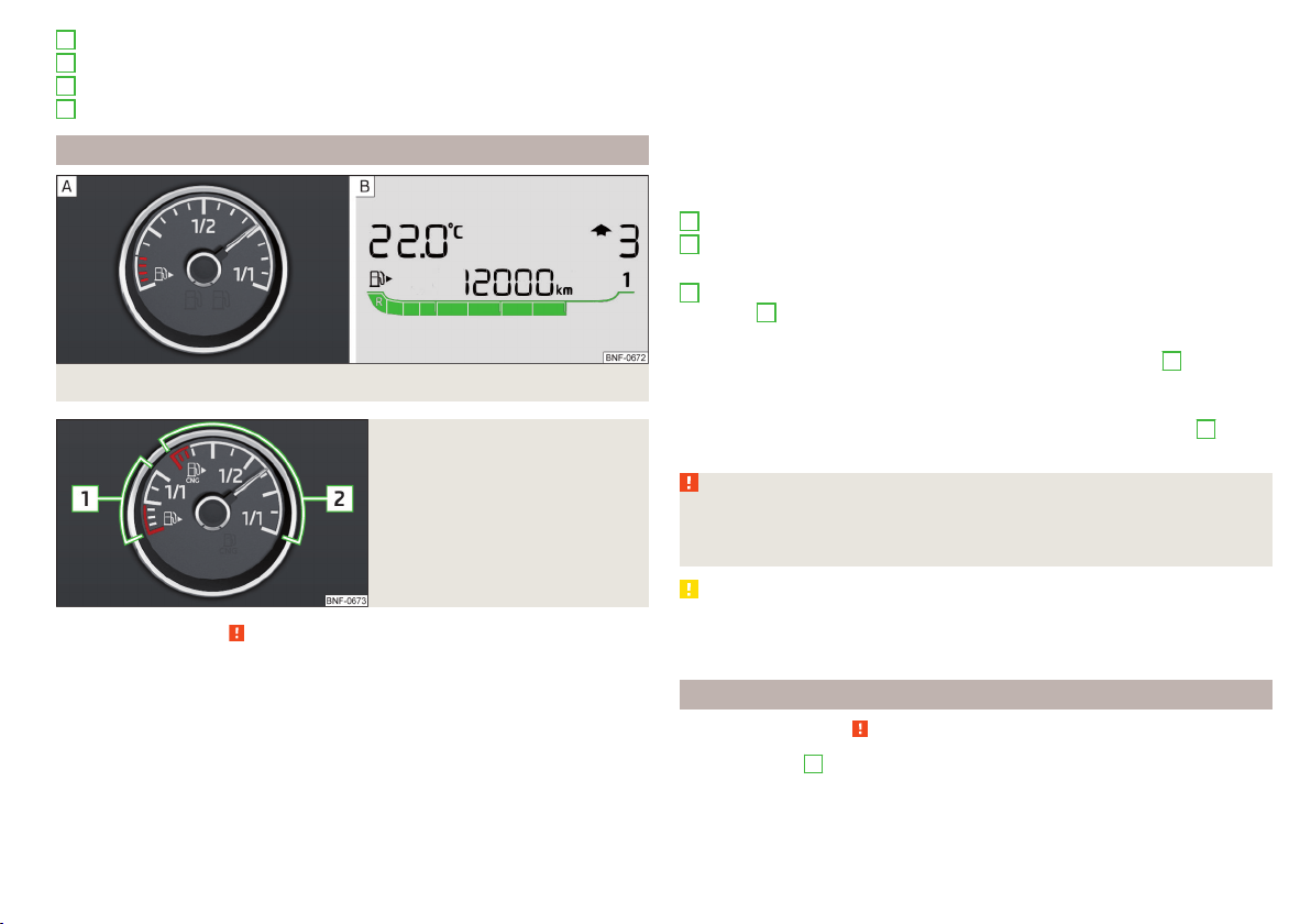
Fig. 20
Petrol fuel gauge: Version 1/version 2
Fig. 21
Petrol and natural gas gauge
Read and observe on page 28 first.
The fuel gauge only works if the ignition is switched on.
Vehicles with petrol engine
Fuel gauge types » Fig. 20
Display in the instrument cluster - Version 1
Display in the instrument cluster display - Version 2
The fuel tank has a capacity of about 35 litres.
3
4
5
6
When the fuel level reaches the reserve area in the fuel tank, the warning light
(the pointer of the display in the red scale area) lights up in the display var-
iant 1 on or it flashes the symbol in the display variant 2 for 10 seconds
to-
gether with the remaining segments of the display. There are now about 4 li-
tres of fuel remaining in the tank.
An audible signal sounds as a warning.
G-TEC vehicles (natural gas drive)
Fuel gauge » Fig. 21
Gasoline reserve
Natural gas reserve
When the vehicle runs on petrol, the pointer of the fuel gauge is in the range
1
» Fig. 21. When the vehicle runs on petrol, the pointer of the fuel gauge is in
the range
2
.
If the fuel level in the fuel tank reaches the reserve area for petrol, the warn-
ing light
goes on. The pointer is in the red range of the gauge
1
» Fig. 21.
There are now about 5 l of fuel remaining in the tank.
If the fuel level in the fuel tank reaches the reserve area for natural gas the
warning light
goes on. The pointer is in the red range of the gauge
2
» Fig. 21. There are now about 1.5 kg of fuel remaining in the tank.
WARNING
In order for the vehicle systems to function properly and thus to make driv-
ing safe, there must be sufficient fuel in the tank. Never drive until the fuel
tank is completely empty - there is a risk of accidents!
CAUTION
Never drive until the fuel tank is completely empty! The irregular supply of fuel
can cause misfiring. This can result in considerable damage to parts of the en-
gine and the exhaust system.
Tachometer
Read and observe on page 28 first.
The tachometer
5
» Fig. 19 on page 28 shows the actual engine speed per mi-
nute.
The beginning of the red scale range of the tachometer indicates the maxi-
mum permitted engine speed of a driven-in and operating warm engine.
1
2
29
Instruments and control lights
Loading ...
Loading ...
Loading ...