Loading ...
Loading ...
Loading ...
22Adjustment
ADJUSTMENT
LIMIT ADJUSTMENT
To avoid SERIOUS personal INJURY or DEATH from
electrocution:
• Disconnect electric power BEFORE performing ANY
adjustments or maintenance.
• ALL maintenance MUST be performed by an Authorized
Service Technician
TO REDUCE THE RISK OF SEVERE INJURY OR DEATH:
IMPORTANT SAFETY INSTRUCTIONS
1. READ AND FOLLOW ALL WARNINGS AND INSTRUCTIONS.
2. ALWAYS keep remote controls out of reach of children.
NEVER permit children to operate or play with door control
push buttons or remote controls.
3. ONLY activate a door when it can be seen clearly, it is
properly adjusted and no obstructions exist in the path the
door will travel.
4. Personnel should keep away from a door in motion and
ALWAYS keep a door in sight until completely closed. NO
ONE SHOULD CROSS THE PATH OF A MOVING DOOR.
5. NO ONE SHOULD GO UNDER A STOPPED OR PARTIALLY
OPENED DOOR.
6. If possible, use the manual release handle to disengage a
door ONLY when a door is CLOSED. Weak or broken springs
or an unbalanced door could result in an open door falling
rapidly and/or unexpectedly causing SEVERE INJURY or
DEATH.
7. NEVER use manual release handle unless the doorway is
clear of persons and obstructions.
8. After ANY adjustments are made, the entrapment protection
device(s) MUST be tested. Failure to adjust the operator
properly may cause SEVERE INJURY and DEATH.
9. Entrapment protection device(s) MUST be tested every
month. Failure to adjust the operator properly may cause
SEVERE INJURY and DEATH.
10. ALWAYS KEEP DOOR PROPERLY BALANCED. An
improperly balanced door may NOT reverse when required
and could result in SEVERE INJURY or DEATH. See the door
manufacturer’s owners manual.
11. ALL repairs to cables, spring assemblies and other
hardware, ALL of which are under EXTREME tension, MUST
be made by an Authorized Service Technician.
12. ALWAYS disconnect electric power to the door operator
BEFORE making ANY repairs or removing covers.
13.
SAVE THESE INSTRUCTIONS.
1
2
3
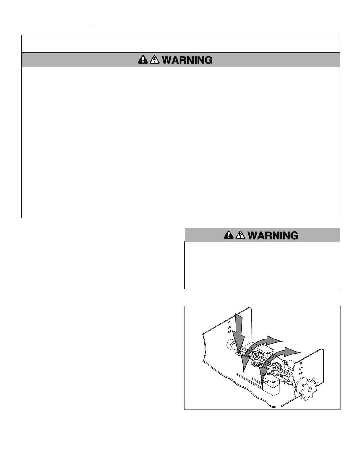
1
Begin with the door in the fully closed position to set the
CLOSE limit.
2
Depress the retaining plate (1) and move the limit nut to the
CLOSE limits (2).
NOTE: The Close Limit Switch (CLS) and Sensing Limit Switch
(SLS) LEDs on the logic board will illuminate when the switches
are activated and the power is on.
3
When the retaining plate is released, verify the retaining plate
is fully seated with the notches of the limit nuts.
4
Open the door to the fully open position and set the OPEN
limit (3).
NOTE: The Open Limit Switch (OLS) LED on the logic board will
illuminate when the switches are activated and the power is on.
5
When the retaining plate is released, verify the retaining plate
is fully seated with the notches of the limit nuts.
NOTE: In some installations, such as a through-wall-installation,
the rotation of the motor and logic board may have to be changed.
1. Locate the MOTOR DIRECTION jumper on the logic board.
Remove jumper and relocate from STD to REV.
2. Relocate the sensing limit switch (SLS) to the opposite side.
3. Remove the CLOSE/OPEN decal and reattach appropriately.
Loading ...
Loading ...
Loading ...