Loading ...
Loading ...
Loading ...
18Wiring
WIRING
To reduce the risk of SEVERE INJURY or DEATH:
• ANY maintenance to the operator or in the area near the
operator MUST NOT be performed until disconnecting the
electrical power and locking-out the power. Upon completion of
maintenance the area MUST be cleared and secured, at that
time the unit may be returned to service.
• Disconnect power at the fuse box BEFORE proceeding. Operator
MUST be properly grounded and connected in accordance with
national and local electrical codes. The operator should be on a
separate fused line of adequate capacity.
• ALL electrical connections MUST be made by a qualified
individual.
• DO NOT install ANY wiring or attempt to run the operator
without consulting the wiring diagram.
• ALL power wiring should be on a dedicated circuit and well
protected. The location of the power disconnect should be
visible and clearly labeled.
• ALL power and control wiring MUST be run in separately.
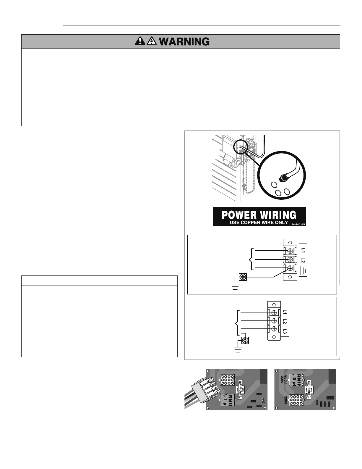
Three Phase Power Wiring
Single Phase Power Wiring
Line Power
115/230 Vac
Single Phase
Hot
Neutral
Ground
Ground
Ground
Phase 1
Phase 2
Phase 3
2
1
Line Power
208/230/460/575 Vac
Three Phase
VOLTAGE SELECTION
POWER AND GROUND
Power and control wiring must be run in separate conduit to
comply with national and local electrical codes. For power wiring,
use the appropriate wire gauge. Use conduit knockouts, conduit
fi ttings, and appropriate conduit fi ttings for wiring as indicated
on the electrical box label.
Locate motor harness inside of the electrical box.
For all operators except for 575V 3 Phase operators, follow the
steps below. The motor harness is connected to the power board
at the factory on all 575V 3 Phase operators.
Remove the operator cover.
1
1
Attach power and ground wires to appropriate terminals.
NOTE: The operator must be properly grounded. Failure to
properly ground the operator could result in electric shock
and serious injury.
3
2
2
Run power wires to electrical box according to national and
local electrical codes.
ON THREE PHASE MACHINES ONLY: Incorrect phasing of
the power supply will cause the motor to rotate in the wrong
direction. To change motor rotation, exchange incoming
power leads L1 and L2.
On the POWER BOARD fi nd the appropriate receptacle
matching the incoming line voltage. Remove the voltage
label and apply to the inside of the electrical box for future
reference. Insert the motor harness fully until locked in place.
DISTANCE GAUGE
50 feet (15.2 m) 14 AWG
100 feet (30.5 m) 12 AWG
200 feet (61 m) 8 AWG*
350 feet (106.7 m) 6 AWG*
500 feet (152.4 m) 4 AWG*
1000 feet (304.8 m) 2 AWG*
POWER WIRING CHART
*
Maximum wire gauge that can be connected to the operator’s
terminal is 12 AWG. When a larger wire gauge is required, the wire
must be gauged down to 12 AWG. USE COPPER WIRE ONLY.
115V 230V
Motor
Harness
SINGLE PHASE POWER BOARD
3 PHASE POWER BOARD
3
Fusing on the 3-Phase Power Board is not fi eld-replaceable. An
Open Fuse indicates that the 3-Phase Power Board is damaged
and must be replaced. Failure to replace the complete 3-Phase
Power Board may result in additional damage to the Operator.
Loading ...
Loading ...
Loading ...