Loading ...
Loading ...
Loading ...
34
A
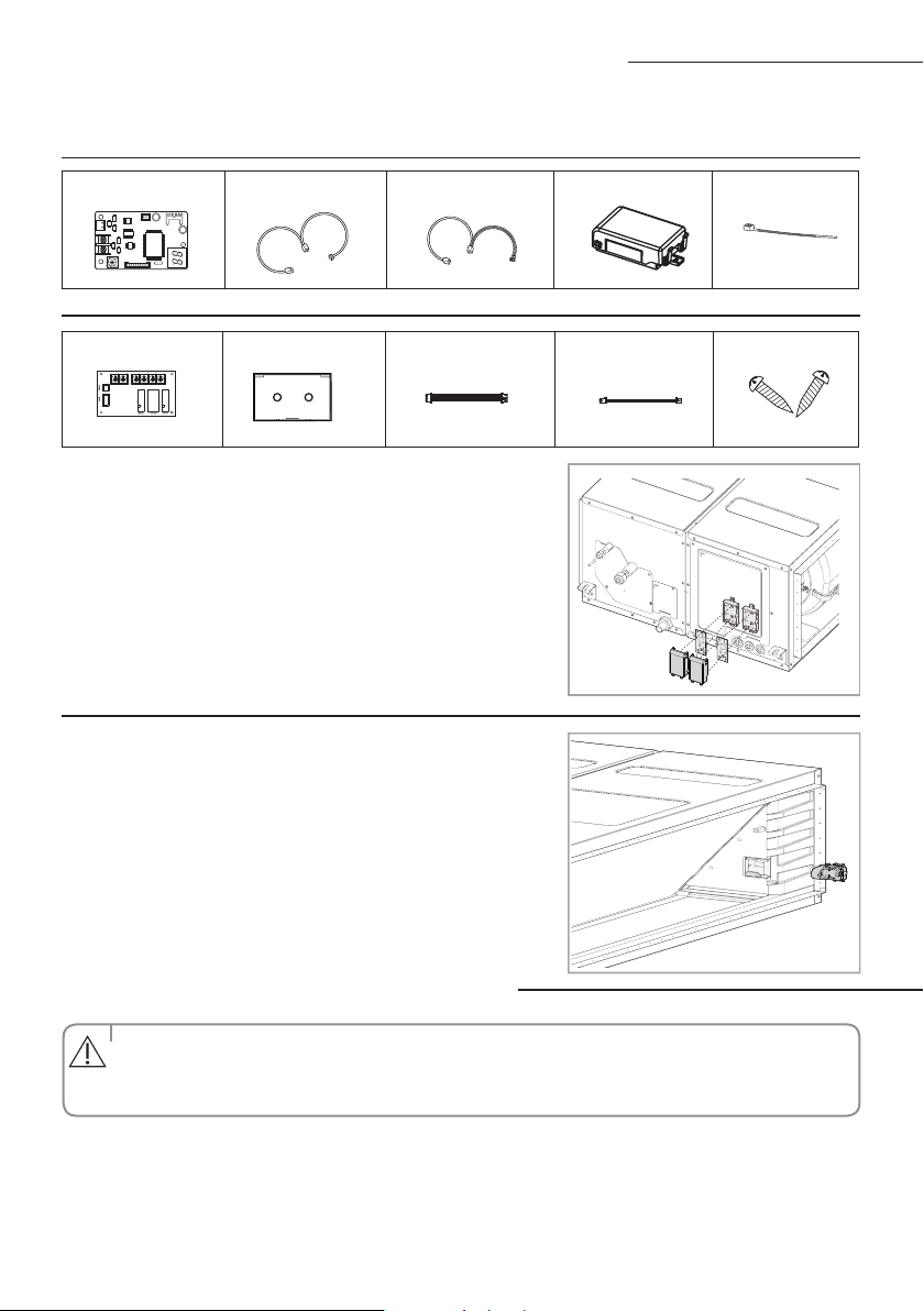
Interface module Installation (Optional)
Interface module DC power cable Communication cable PCB Case Cable-tie
Accessories (Interface module : MIM-B13D)
1. Fix the case at with bolts on the side of the control box in the indoor unit.(See the
picture)
2. Attach the Interface module PCB to the case in the control box of the indoor unit,
then connect the power and the communication cable between the Interface
module and the indoor unit;
3. If you install a Interface module to an indoor unit, every outdoor unit which is
connected to an indoor unit can be controlled simultaneously.
4. Each indoor unit connected to the same centralized
controller has its own
Interface module.
Accessories (SPI module : MSD-EAN1)
Refer to the
SPI
module(MSD-EAN1) installation manual for the more information.
Accessories (Interface module : MIM-B14)
External Control PCB Case Haness Wire(2P) Haness Wire (4P) Screw
Connecting the connection cord
• Alwaysremembertoconnecttherefrigerantpipesbeforeperformingtheelectricconnections.
When disconnecting the system, always disconnect the electric cables before disconnecting the refrigerant pipes.
• Alwaysremembertoconnecttheairconditionertothegroundingsystembeforeperforming
the electric connections.
The indoor unit is powered by the outdoor unit by means of a H07 RN-F connection cable (or a more power model),
with insulation in synthetic rubber and jacket in polychloroprene(neoprene), in accordance with the requirements of standard EN 60335-2-40.
1. Remove the screw on the electrical component box and remove the cover plate.
2. Route the connection cord through the side of the indoor unit and connect the cable to terminals; refer to the gure below.
3. Route the other end of the cable to the outdoor unit through the ceiling & the hole on the wall.
4. Reassemble the electrical component box cover, carefully tightening the screw.
CAUTION
ACJNHFKH model only
Loading ...
Loading ...
Loading ...