Loading ...
Loading ...
Loading ...
9
1.7 QUICK START
This quick start section includes just enough information to
get the MDA operational and to run Anthem Room Correction.
For a deeper understanding of speaker and subwoofer con-
nection options, advanced conguration settings, and control
system integration, please review the rest of this manual.
ANALOG OUT
RL
LR
1. Install the MDA in a rack or install the feet using a Phillips
screwdriver for tabletop operation. (Rack brackets can be
removed using a T10 Torx driver).
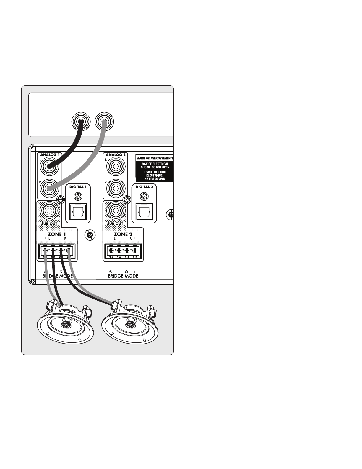
2. Speaker Connection(s): Connect a pair of speakers to
Zone 1 using a Euroblock (aka Phoenix
TM
) connector (in-
cluded) which accepts speaker wire from 28 up to 12 gauge.
a. Pull both sides of the Euroblock connector from Zone 1
to remove it from the MDA.
b. Use a small slotted screwdriver to loosen and tight-
en each contact on the Euroblock when inserting the
speaker wire.
c. Follow positive (+) and negative (–) indications shown
on the Euroblock connector.
d. After attaching speaker wires to the Euroblock connec-
tor, insert it back into the MDA.
3. Repeat to connect speakers in additional zones.
4. Input Connections(s): Connect analog sources using RCA
cables. By default, Analog 1 plays in Zone 1, Analog 2 in
Zone 2, and so on. You can change source assignments
later if so desired.
5. Power Connection: Insert a power cord into the MDA’s AC
input. Plug the cord into a wall outlet. Make sure to respect
the voltage rating shown beside the AC receptacle.
BASIC CONFIGURATION
1. Control Settings:
a. On Mode Switch: Set to Auto.
b. Master AC Power Switch: Set to On.
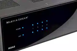
2. When the MDA detects audio in a zone, the corresponding
indicator light (at the bottom) turns blue, and the zone’s
power indicator light (at the top) turns blue. You should
now hear the music.
ADVANCED CONFIGURATION AND CONTROL
SYSTEM INTEGRATION
1. Control Settings:
a. On Mode Switch: Set to Ext Cmd.
b. Master AC Power Switch: Set to On.
2. Network Connection: Connect the MDA’s Network con-
nection to a LAN using an Ethernet cable. The network
router should support DHCP and will automatically assign
an IP address to the MDA.
3. Powered subwoofer connection(s) [optional]: Connect a
powered subwoofer to Zone 1 using an RCA cable. Repeat
to connect subwoofers in additional zones.
5. Input Connections(s): Connect each audio source using
the desired connection method.
a. Analog Left/Right RCA: Connect to Analog inputs.
b. Digital, Optical (aka Toslink): Connect to Digital 1 or
2 (Digital 1 only on MDA8).
c. Digital, Coaxial: Connect to Digital 3 or 4 (not available
on MDA8).
ACCESSING THE CONFIGURATION INTERFACE
For initial setup, the MDA should be connected to a network
and plugged into the wall with the On Mode switch set to EXT
CMD. Turn on the MDA by setting the master power switch to
On. The Power light on the front panel indicates that the MDA
has powered up. Once the LAN light on the front panel turns
blue or red, the MDA has connected to your network and ac-
quired a network address.
Loading ...
Loading ...
Loading ...