Operating Manual
MDA16
MDA8
®
2
WARNING: To reduce the risk of re or electric shock, do not
expose this apparatus to rain or moisture, and objects lled
with liquids, such as vases, should not be placed on this ap-
paratus.
CAUTION: To prevent electric shock, match wide blade of plug
to wide slot, fully insert.
CAUTION: For continued protection against risk of re, re-
place the fuse only with the same amperage and voltage type.
Refer replacement to qualied service personnel.
WARNING: Unit may become hot. Always provide adequate
ventilation to allow for cooling. Do not place near a heat
source, or in spaces that can restrict ventilation.
IMPORTANT SAFETY INSTRUCTIONS
1. Read these instructions.
2. Keep these instructions.
3. Heed all warnings.
4. Follow all instructions.
5. Do not use this apparatus near water.
6. Clean only with a dry cloth.
7. Do not block any of the ventilation openings. Install in
accordance with the manufacturer’s instructions.
8. Do not install near any heat sources such as radiators,
heat registers, stoves or other apparatus (including am-
pliers) that produce heat.
9. Do not defeat the safety purpose of the polarized plug.
A polarized plug has two blades with one wider than the
other. The wide blade is provided for your safety. When
the provided plug does not t into your outlet, consult an
electrician for replacement of the obsolete outlet.
10. Protect the power cord from being walked on or pinched,
particularly at plugs, convenience receptacles and the
point where they exit from the apparatus.
11. Only use the attachments/accessories specied by the
manufacturer.
12. Use only with a cart, stand, tripod, bracket
or table specied by the manufacturer, or
sold with the apparatus. When a cart is used,
use caution when moving the cart/apparatus
combination to avoid injury from tip-over.
13. Unplug this apparatus during lightning storms or when
unused for long periods of time.
14. Refer all servicing to qualied service personnel. Servic-
ing is required when the apparatus has been damaged
in any way, such as power supply cord or plug is dam-
aged, liquid has been spilled or objects have fallen into
the apparatus, the apparatus has been exposed to rain
or moisture, does not operate normally, or has been
dropped.
WARNING: To reduce the risk of re or electric shock, do not
expose this apparatus to rain or moisture. Avoid installing
this unit where foreign objects may fall onto this unit and/or
this unit may be exposed to liquid dripping or splashing. On
the top of this unit, do not place:
• Burning objects (i.e. candles), as they may cause re dam-
age to this unit, and/or personal injury.
• Containers with liquid in them, as they may fall and liquid
may cause electrical shock to the user and/or damage to
this unit.
Apparatus shall not be exposed to dripping or splashing and
no objects lled with liquids, such as vases, shall be placed on
the apparatus.
CAUTION: TO REDUCE THE RISK OF ELECTRIC SHOCK, DO NOT REMOVE COVER (OR BACK).
NO USER-SERVICEABLE PARTS INSIDE. REFER SERVICING TO QUALIFIED SERVICE PERSONNEL.
RISK OF ELECTRIC SHOCK DO NOT OPEN
The lightning ash with arrowhead
symbol within an equilateral triangle is
intended to alert the user to the presence
of uninsulated “dangerous voltage”
within the product’s enclosure that may
be of sucient magnitude to constitute a
risk of electric shock to persons.
The exclamation point within an
equilateral triangle is intended to
alert the user to the presence of
important operating and maintenance
(servicing) instructions in the literature
accompanying the appliance.
CAUTION
Do not install this equipment in a conned space such as a
case or similar. Install it away from direct sunlight, heat sourc-
es, vibration, dust, moisture, and/or cold.
Do not cover this unit with a newspaper, tablecloth, curtain,
etc. in order not to obstruct heat radiation. If the temperature
inside this unit rises, it may cause re, damage to this unit,
and/or personal injury.
Install this unit near the AC outlet and where the AC power
plug can be reached easily.
This unit is not disconnected from the AC power source when it
is turned o. This state is called the standby mode. In this state,
this unit is designed to consume a very small quantity of power.
NOTE: This product is not an auto voltage device. Connect
only to the prescribed AC outlet, i.e., 120V 50/60Hz or 240V
50/60Hz.
CAUTION: Top surface can become hot.
CAUTION: These servicing instructions are for use by qualied
service personnel only. To reduce the risk of electric shock,
do not perform any servicing other than that contained in the
operating instructions unless you are qualied to do so.
CAUTION: Changes or modications to this equipment not
expressly approved by MartinLogan for compliance could void
the user’s authority to operate this equipment.
FCC WARNING: Changes or modications not expressly ap-
proved by the party responsible for compliance could void the
user’s authority to operate the equipment.
This equipment has been tested and found to comply with the
limits for a class B digital device, pursuant to part 15 of the
FCC Rules. These limits are designed to provide reasonable
protection against harmful interference in a residential instal-
lation. This equipment generates, uses and can radiate radio
frequency energy and, if not installed and used in accordance
with the instructions, may cause harmful interference to radio
communications. However, there is no guarantee that inter-
ference will not occur in a particular installation. If this equip-
ment does cause harmful interference to radio or television
reception, which can be determined by turning the equipment
o and on, the user is encouraged to try to correct the inter-
ference by one or more of the following measures:
• Reorient or relocate the receiving antenna.
• Increase the separation between the equipment and MDA.
• Connect the equipment into an outlet on a circuit dierent
from that to which the MDA is connected.
• Consult the dealer or an experienced radio / TV technician
for help.
DO NOT LOCATE IN THE FOLLOWING PLACES:
To ensure long-lasting use, do not locate the unit:
• Exposed to direct sunlight.
• Near sources of heat such as heaters.
• Highly humid or poorly ventilated.
• Dusty.
• Subjected to mechanical vibrations.
• On wobbly, inclined, or otherwise unstable surfaces.
• Near windows where there is a chance of exposure to rain,
etc.
• On top of an MDA or another component which dissipates
a great deal of heat.
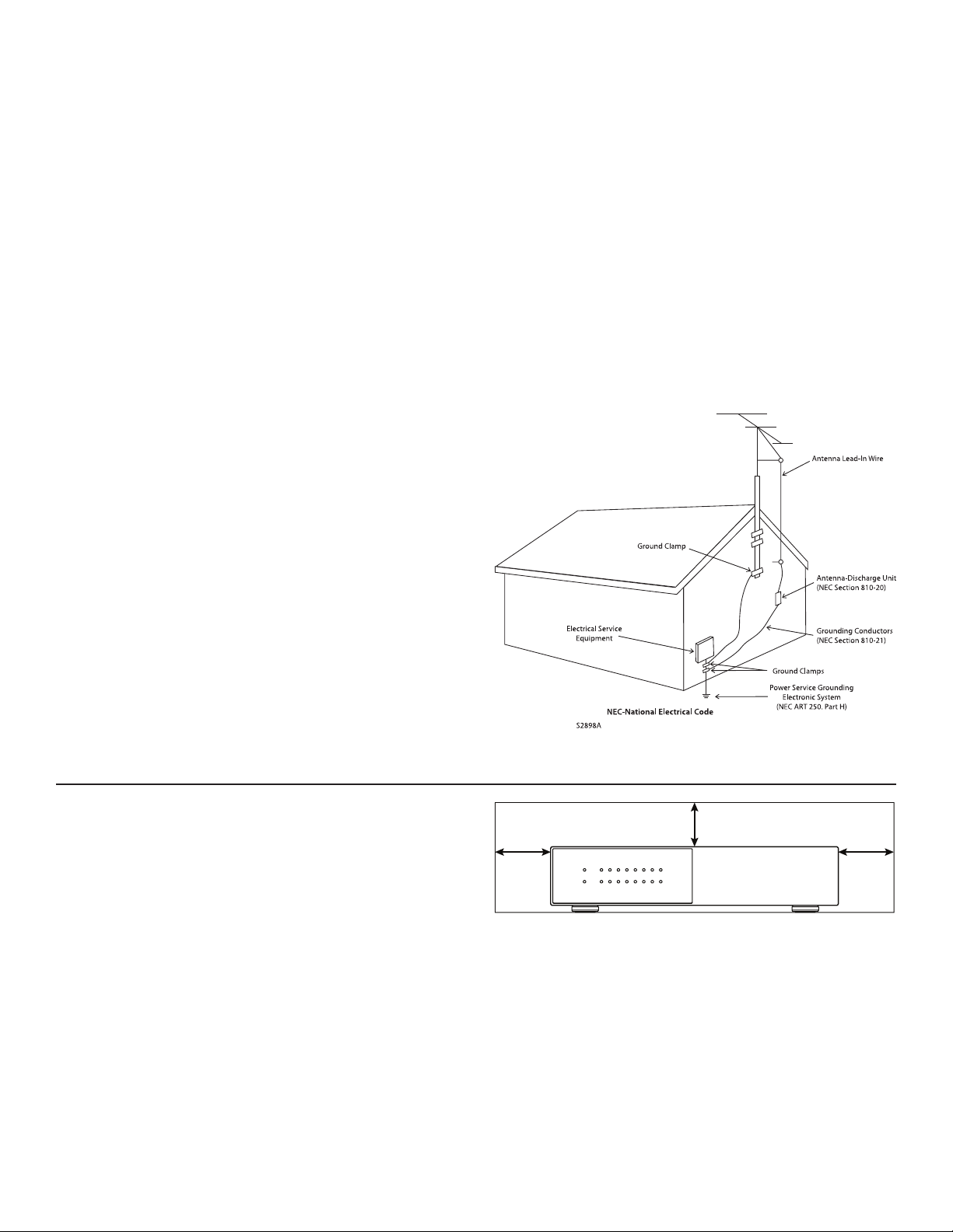
To ensure proper heat radiation, ensure clearance from walls
and other equipment according to the diagram.
Left: 63mm
(2.5 in) or more
Above: 15mm
(0.6 in) or more
Right: 63mm
(2.5 in) or more
4
IMPORTANT INFORMATION FOR UK CUSTOMERS: DO NOT cut
o the mains plug from this equipment. If the plug tted is not
suitable for the power points in your home or the cable is too
short to reach a power point, then obtain an appropriate safety
approved extension lead or consult your dealer. If, nonetheless,
the mains plug is cut o, REMOVE THE FUSE and dispose of the
PLUG immediately, to avoid possible shock hazard by inadver
-
tent connection to the mains supply. If this product is not pro-
vided with a mains plug, or one has to be tted, then follow the
instructions given below:
IMPORTANT: DO NOT make any connection to the larger ter
-
minal which is marked with the letter “E” or by the safety earth
symbol or colored GREEN or GREEN AND YELLOW.
The wires in the mains lead on this product are colored in accor
-
dance with the following code:
• BLUE – NEUTRAL
• BROWN – LIVE
As these colors may not correspond with the colored markings
identifying the terminals in your plug, proceed as follows:
• The BLUE wire must be connected to the terminal marked
with the letter “N” or colored BLACK.
• The BROWN wire must be connected to the terminal marked
with the letter “L” or colored RED.
When replacing the fuse, only a correctly rated and approved
type should be used, and be sure to ret the fuse cover. If in
doubt, consult a competent electrician.
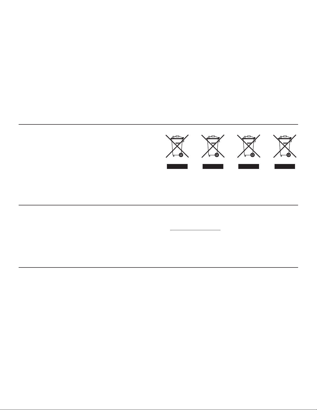
NOTES ON ENVIRONMENTAL PROTECTION
At the end of its useful life, this product must not be disposed
of with regular household waste but must be returned to a
collection point for the recycling of electrical and electronic
equipment. The symbol on the product, the user’s manual,
and the packaging point this out. The materials can be reused
in accordance with their markings. Through reuse, recycling of
raw materials or other forms of recycling of old products, you
are making an important contribution to the protection of our
environment. Your local administrative oce can advise you
of the responsible waste disposal point.
CdHgPb
RECYCLING AND REUSE GUIDELINES (Europe)
In accordance with the European Union WEEE (Waste Electri-
cal and Electronic Equipment) directive eective August 13,
2005, we would like to notify you that this product may con-
tain regulated materials which, upon disposal, require special
reuse and recycling processing. For this reason, MartinLogan
has arranged with its distributors in European Union mem-
ber nations to collect and recycle this product at no cost to
you. To nd your local distributor, please contact the dealer
from whom you purchased this product or go to our website
at www.MartinLogan.com.
Please note that only the product falls under the WEEE direc-
tive. When disposing of packaging and other shipping materi-
al, we encourage you to recycle through the usual channels.
MartinLogan and any related party assume no liability for the
user’s failure to comply with any requirements.
MartinLogan is registered trademarks of MartinLogan, Ltd.
©MartinLogan, Ltd. All rights reserved.
Anthem, ARC, and Paradigm are trademarks or registered
trademarks of Paradigm Electronics Inc. © Paradigm Electron-
ics Inc. All rights reserved.
The information contained herein may not be reproduced in
whole or in part without our express written permission. We
reserve the right to change specications or features without
notice as design improvements are incorporated.
All other trademarks are the property of their respective
owners.

5
TABLE OF CONTENTS
1. Introduction and Quick Start . . . . . . . . . . . . . . . . . . . . . 6
1.1 Before Making Connections ..................6
1.2 Box Contents . . . . . . . . . . . . . . . . . . . . . . . . . . . . . . . 6
1.3 In-Use Notices ..............................6
1.4 Rack and Shelf Mounting .....................6
1.5 Front Panel (Status Lights) ....................7
1.6 Back Panel .................................8
1.7 Quick Start .................................9
1.8 Setting Up a Control System .................10
2. The User Interface .............................11
2.1 Accessing the User Interface .................11
2.2 Finding the MDA’s IP Address ................11
2.3 Identifying Multiple MDAs ...................11
2.4 Zones ....................................12
2.5 Inputs Settings.............................14
2.6 General: Preferences .......................15
2.7 General: Information .......................16
2.8 General: Network Settings...................17
2.9 General: Input Status .......................18
2.10 Store/Load Settings.........................19
3. Connections and Back Panel Controls ............20
3.1 Local Area Network Connection . . . . . . . . . . . . . . 20
3.2 Speaker Connections .......................20
3.3 Connecting Stereo Speakers . . . . . . . . . . . . . . . . . 21
3.4 Connecting Mono Speakers
Using One Bridged Zone ...................22
3.5 Connecting Stereo Speakers
Using Two Bridged Zones ..................23
3.6 Subwoofer Outputs.........................24
3.7 Connecting a Passive (Non-Powered)
Subwoofer Using a Bridged Zone............25
3.8 Digital Inputs ..............................26
3.9 Digital Output (MDA16 Only) .................26
3.10 Analog Input...............................26
3.11 Analog Outputs (MDA16 Only) ...............26
3.12 Power ....................................26
3.13 Trigger Connections ........................26
3.14 RS-232 Conneciton .........................26
3.15 On Mode Switch ...........................26
3.16 Master Power Switch .......................26
3.17 DHCP or Factory Image Reset ................26
3.18 ID Indicator................................26
3.19 ARC Micro-USB Connection ..................27
3.20 Chassis Ground ............................27
3.21 Fuse......................................27
4. Anthem Room Correction .......................28
4.1 Using ARC With an MDA ......................29
5. Updating Firmware.............................30
5.1 Updating Firmware
(Using an Internet Connection)..............30
5.2 Updating Firmware
(Without an Internet Connection) ...........30
6. Fault Modes ...................................31
6.1 Front Panel Power LED......................31
6.2 Front Panel LAN LED........................31
6.3 Front Panel Zone LEDs ......................31
7. Troubleshooting ...............................32
8. Frequently Asked Questions.....................33
9.Specications..................................34
10. Limited Warranty ..............................35
11. The Big Picture: MDA16 .........................38
12. The Big Picture: MDA8 ..........................40

6
1. INTRODUCTION AND QUICK START
Thank you for purchasing the MartinLogan MDA. All MartinLo-
gan products are engineered to recreate the passion of a live
musical performance and emotional involvement experienced
in the best movie theaters by utilizing the highest level of cir-
cuit design, superior parts and manufacturing techniques, in-
novative features, and intuitive ergonomics. We are condent
that their inclusion in a system signicantly enhances the en-
joyment of recordings.
1.1 BEFORE MAKING CONNECTIONS
Check that you have received all items listed below and report
discrepancies to your dealer as soon as possible. In case the
MDA needs to be transported in the future, keep the packing
materials. Retain the invoice that you received from your au-
thorized MartinLogan dealer at time of purchase. The invoice
is necessary to obtain service under warranty.
1.2 BOX CONTENTS
• MDA8 or MDA16
• Dual-jack microphone
• USB mini (Type B) cable for ARC microphone
• 3.5mm cable for ARC microphone (for future ARC Mobile
app support)
• 3.5 mm trigger cable
• IEC power cord(s) (US type for 120V model, EU/UK/AU type
for 230V model)
• 2x Rack brackets (preinstalled)
• 4x Feet (if tabletop operation required)
• 4x Phillips head screws (for attaching feet)
• MDA16: 8x Euroblock Connectors (preinstalled)
• MDA8: 4x Euroblock Connectors (preinstalled)
1.3 IN-USE NOTICES
• Disconnect the power cord or ip the AC switch to OFF be-
fore connecting or disconnecting any components.
• If the MDA was transported or stored in the cold, let it
reach room temperature before use.
• Do not remove the top cover.
• Do not modify the product.
• Due to continuing advances, operational characteristics
may change. If this manual contains discrepancies, please
check www.MartinLogan.com for the latest manual.
1.4 RACK AND SHELF MOUNTING
These MDAs ship with rack brackets installed. If shelf mount-
ing is desired, you can remove the rack brackets using a T10
Torx driver. Using a Phillips screwdriver, attach four feet to the
bottom of the MDA using the included screws.
7
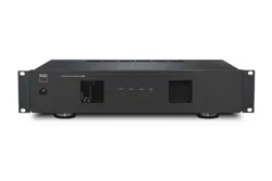
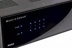
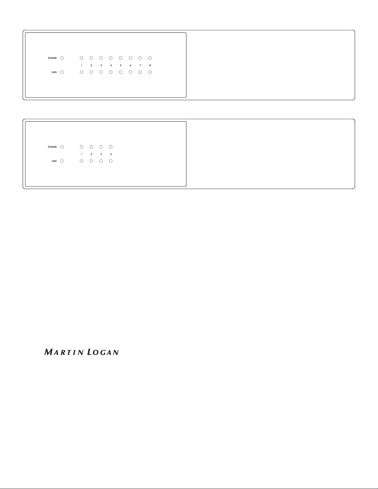
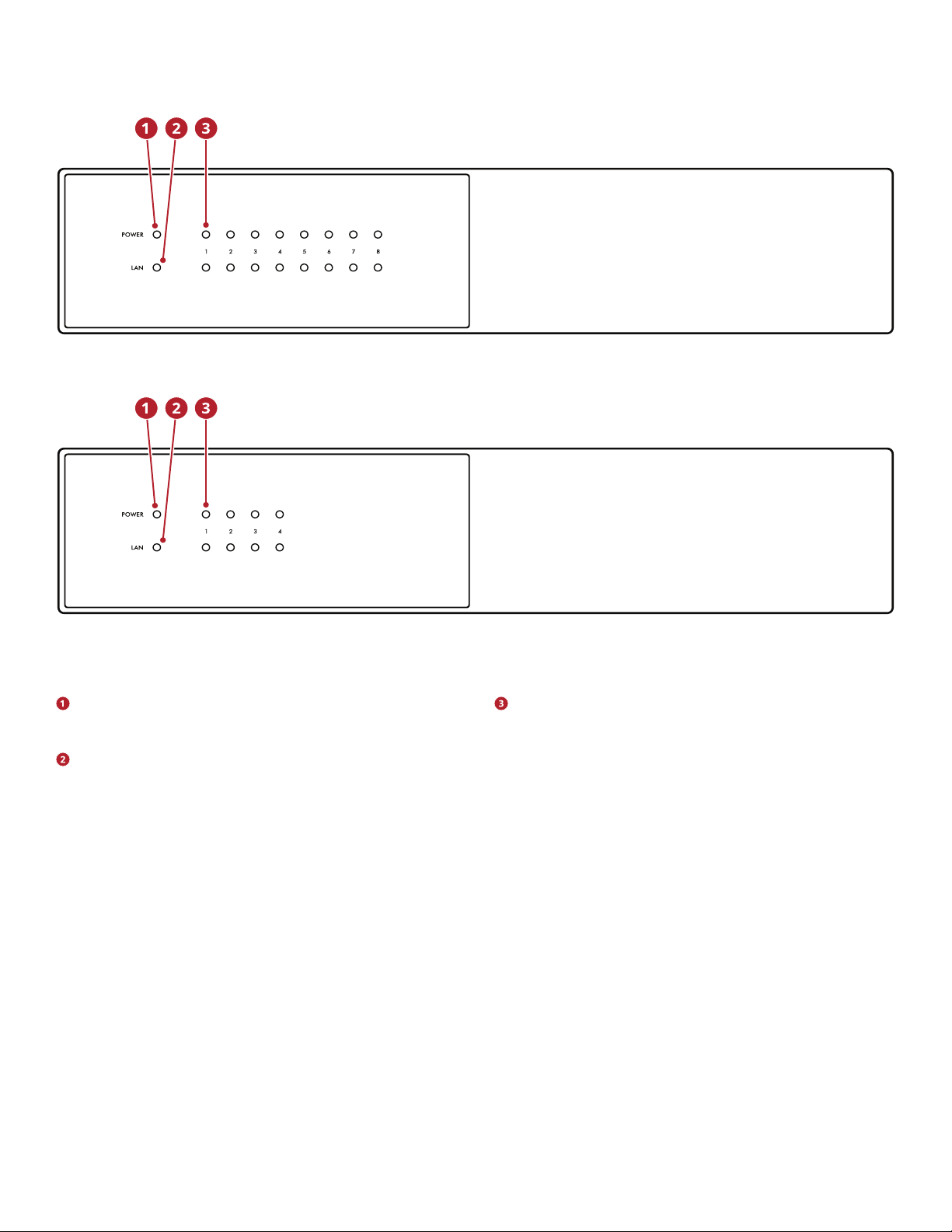
MDA16 Front Panel
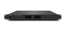
MDA8 Front Panel
1.5 FRONT PANEL (STATUS LIGHTS)
Power: When blue, the MDA is on and ready to play. When
red, the MDA has entered network standby mode.
LAN: When blue, a 100M or faster network is connected.
Red indicates a 10M connection. When o, there is no net-
work connection.
Numbers: When the top indicator turns blue, the indicat-
ed channel is active. The bottom indicator turns blue when
audio is detected. When ashing blue or red, it is in fault
mode.
For more information, please refer to sections 6 (Fault Modes)
and 7 (Troubleshooting).
8
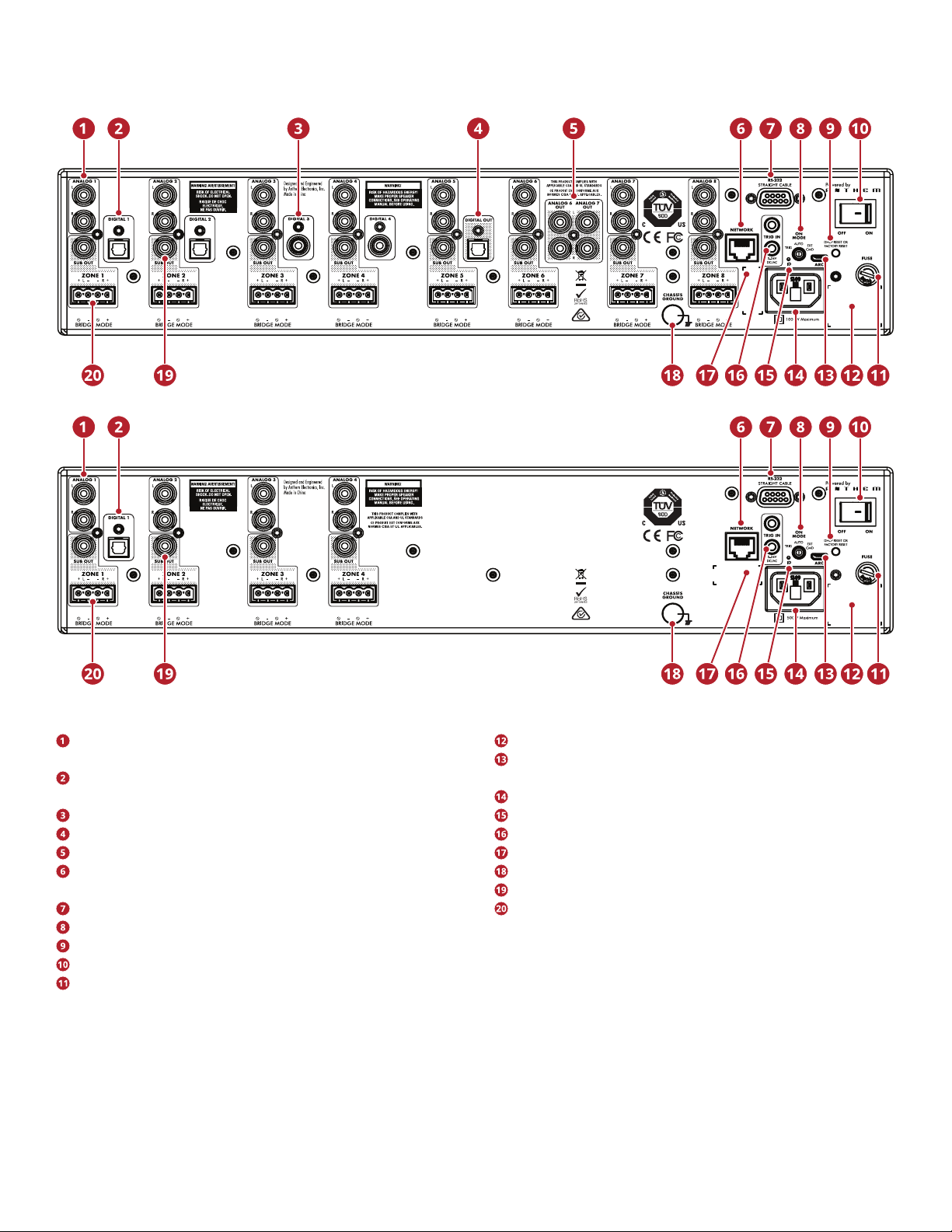
1.6 BACK PANEL
Analog RCA stereo inputs (MDA16 has eight, MDA8 has
four)
Optical digital audio inputs (MDA16 has two, MDA8 has
one)
Coaxial digital audio inputs (MDA16 only)
Optical digital audio output (MDA16 only)
Zone 6 and 7 analog outputs (MDA16 only)
Ethernet connection for ARC (Anthem Room Correction),
software installation, and control
RS-232 (serial) connection for legacy control
On mode switch (trigger / auto / external command)
DHCP reset / factory reset
Master power switch
Fuse
Serial number label
Micro USB type B for ARC via PC or Mac (if LAN is not avail-
able)
Power cord inlet (IEC C18 type)
Rear ID (identify) light
5–24V DC/AC 3.5 mm trigger input/loop
MAC address label
Chassis ground terminal
Subwoofer outputs (MDA16 has eight, MDA8 has four)
Euroblock speaker terminals
For more information, please refer to section 3 (Connections
and Back Panel Controls).
MDA16 Back Panel
MDA8 Back Panel
9
1.7 QUICK START
This quick start section includes just enough information to
get the MDA operational and to run Anthem Room Correction.
For a deeper understanding of speaker and subwoofer con-
nection options, advanced conguration settings, and control
system integration, please review the rest of this manual.
ANALOG OUT
RL
LR
1. Install the MDA in a rack or install the feet using a Phillips
screwdriver for tabletop operation. (Rack brackets can be
removed using a T10 Torx driver).
2. Speaker Connection(s): Connect a pair of speakers to
Zone 1 using a Euroblock (aka Phoenix
TM
) connector (in-
cluded) which accepts speaker wire from 28 up to 12 gauge.
a. Pull both sides of the Euroblock connector from Zone 1
to remove it from the MDA.
b. Use a small slotted screwdriver to loosen and tight-
en each contact on the Euroblock when inserting the
speaker wire.
c. Follow positive (+) and negative (–) indications shown
on the Euroblock connector.
d. After attaching speaker wires to the Euroblock connec-
tor, insert it back into the MDA.
3. Repeat to connect speakers in additional zones.
4. Input Connections(s): Connect analog sources using RCA
cables. By default, Analog 1 plays in Zone 1, Analog 2 in
Zone 2, and so on. You can change source assignments
later if so desired.
5. Power Connection: Insert a power cord into the MDA’s AC
input. Plug the cord into a wall outlet. Make sure to respect
the voltage rating shown beside the AC receptacle.
BASIC CONFIGURATION
1. Control Settings:
a. On Mode Switch: Set to Auto.
b. Master AC Power Switch: Set to On.
2. When the MDA detects audio in a zone, the corresponding
indicator light (at the bottom) turns blue, and the zone’s
power indicator light (at the top) turns blue. You should
now hear the music.
ADVANCED CONFIGURATION AND CONTROL
SYSTEM INTEGRATION
1. Control Settings:
a. On Mode Switch: Set to Ext Cmd.
b. Master AC Power Switch: Set to On.
2. Network Connection: Connect the MDA’s Network con-
nection to a LAN using an Ethernet cable. The network
router should support DHCP and will automatically assign
an IP address to the MDA.
3. Powered subwoofer connection(s) [optional]: Connect a
powered subwoofer to Zone 1 using an RCA cable. Repeat
to connect subwoofers in additional zones.
5. Input Connections(s): Connect each audio source using
the desired connection method.
a. Analog Left/Right RCA: Connect to Analog inputs.
b. Digital, Optical (aka Toslink): Connect to Digital 1 or
2 (Digital 1 only on MDA8).
c. Digital, Coaxial: Connect to Digital 3 or 4 (not available
on MDA8).
ACCESSING THE CONFIGURATION INTERFACE
For initial setup, the MDA should be connected to a network
and plugged into the wall with the On Mode switch set to EXT
CMD. Turn on the MDA by setting the master power switch to
On. The Power light on the front panel indicates that the MDA
has powered up. Once the LAN light on the front panel turns
blue or red, the MDA has connected to your network and ac-
quired a network address.
10
The MDA is congured using an interface accessed using a
web browser. Identify the MDA’s IP address to proceed. You
can discover the MDA’s IP address using the ARC Genesis
software (available on AnthemARC.com). Start the program,
choose Launch ARC, and hover your mouse cursor over the
MDA, wait for a second, and it shows the IP address in the de-
vice discovery screen. Note that the last few characters of the
unit’s name correspond to the end of the MAC address printed
at the back of the MDA.
To access the MDA’s conguration interface, open a web
browser (we recommend Chrome or Safari), type the IP ad-
dress into the browser’s address bar, and hit enter.
When installing more than one MDA, there are multiple IP ad-
dresses. To identify each MDA, use a web browser to connect
to the rst one and click General > Preferences > Unit ID. The
ID light on the back panel ashes as will the Power indicator
on the front of the MDA. The MAC Address displayed under
General > Information matches the unique MAC Address
printed on the back of the MDA.
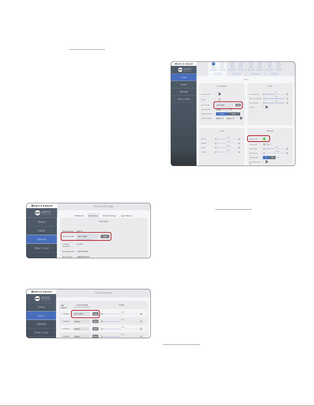
CONFIGURING THE MDA
1. Access the conguration interface by entering the MDA’s IP
address in a web browser’s address bar.
2. General > Information > Device Name: Create a name
for the MDA and click Apply.
3. Inputs > Analog 1 (or other input) > Input Name: Create
a name and click Apply
4. Repeat for additional inputs.
5. Zones > Zone 1 > Zone Settings >
a. Zone Name: Create a name and click Apply.
b. Input Source: Choose the input you want to hear in
this zone.
c. SpeakerProle:Select the type of speaker connected
or keep them as Generic type if not shown in the list.
6. Zones > Zone 1 > Subwoofer > Subwoofer: When there is
a sub connected to the zone’s Sub Out, set the toggle to on.
7. Repeat for additional zones.
RUNNING ANTHEM ROOM CORRECTION (ARC
®
)
Once speakers and subwoofers are connected and cong-
ured, and sources and zones are named, you can run room
correction for each zone that is being used. Download the ARC
Genesis software from AnthemARC.com and follow the on-
screen instructions. See section 4 for additional details.
CONTROLLING THE MDA
Play music using one of the sources connected to the MDA. In
most installations, a custom integrated control system is used
to adjust the volume and change which source is playing in
which zone. You can also adjust volume and change inputs
using the conguration interface.
• Access the conguration interface by entering the MDA’s IP
address in a web browser’s address bar.
• Zones > Zone 1 (or another zone) > Zone Settings > Input
Source: Choose the input you want to hear in this zone.
• Zones > Zone 1 (or another zone) > Volume > Zone Vol-
ume: Adjust the volume here.
1.8 SETTING UP A CONTROL SYSTEM
MDAs are compatible with IP and RS232 command protocols. A
detailed command set and discovery protocol are available on
MartinLogan.com. A variety of MartinLogan developed automa-
tion drivers are also available for download free-of-charge from
our web site for easy integration into a smart-home powered by
Crestron, Savant, and other similar controllers.

11
For optimum performance and enjoyment, your MDA should
be appropriately set up. If you’re using a subwoofer or sub-
woofers, ARC (Anthem Room Correction) sets crossovers and
levels for a perfect blend with the main speakers. The rest of
the settings mostly relate to your preferences. Please fully
congure all zones with the proper output modes (single-end-
ed, stereo or mono bridge), speaker prole and subwoofer
settings (present or not, active or passive) before running ARC.
2.1 ACCESSING THE USER INTERFACE
For initial setup, the MDA should be connected to a network
and plugged into the wall with the On Mode switch set to Auto.
Turn on the MDA by setting the master power switch to On.
The Power light on the front panel indicates that the MDA has
powered up. Once the LAN light on the front panel turns blue
or red, the MDA has connected to your network and acquired
a network address.
2.2 FINDING THE MDA’S IP ADDRESS
The MDA is congured using an interface accessed using a
web browser. Identify the MDA’s IP address to proceed.
You can discover the MDA’s IP address using the ARC Gene-
sis software. Start the ARC program on a PC or Mac, choose
Launch ARC, and hover your mouse cursor over the MDA, wait
for a second, and it shows the IP address in the device discov-
ery screen.
We also recommend using Fing, a free network device detec-
tion app available on iOS, Android, and Windows. This app
identies devices on a network and shows their IP addresses.
These identify with MDA8 or MDA16 or MartinLogan.
To access the MDA’s conguration interface, open a web
browser (we recommend Chrome or Safari), type the IP ad-
dress into the browser’s address bar, and hit enter.
2.3 IDENTIFYING MULTIPLE MDAs
When installing more than one MDA, there are multiple IP ad-
dresses. To identify each MDA, use a web browser to connect
to the rst one and set General > Preferences > Unit ID to On.
The ID light on the MDA’s back panel and the Power indicator
on the front ash. The MAC Address displayed under General
> Information also matches the unique MAC Address printed
on the back of the MDA. Note that the last few characters of
the factory default unit’s name correspond to the end of the
MAC address printed at the back of the MDA.
2. THE USER INTERFACE
12
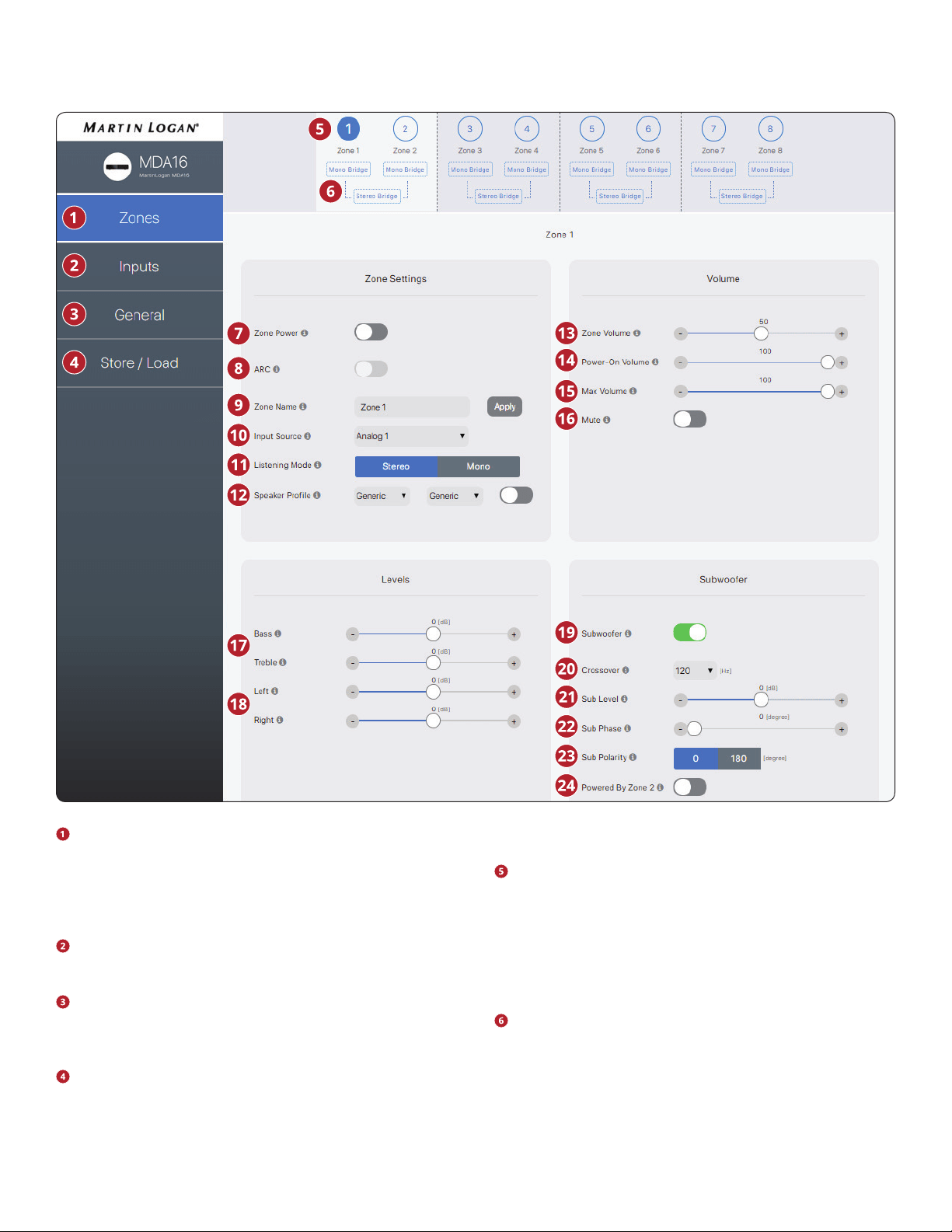
Zones: Adjusts the settings of individual zones, allowing
zone naming, source selection, mode setup, listening
mode, speaker prole, level adjustment, tone control, vol-
ume conguration, and subwoofer setup. The top of the
page shows the individual zones.
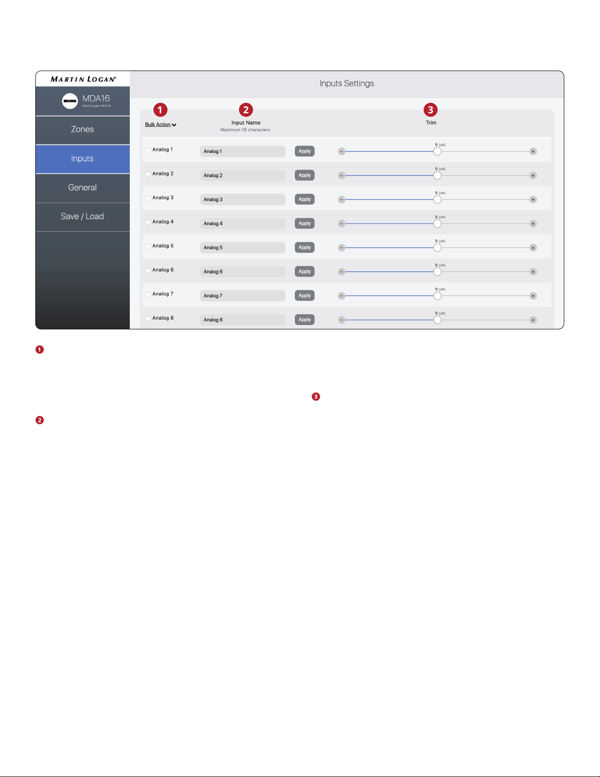
Inputs: Allows input naming and level balancing (trim). See
section 2.5 for additional details.
General: Displays device information and allows device
naming, network conguration, and displays input selec-
tion. See sections 2.6 – 2.9 for additional details.
Store/Load: Allows import/export of device settings from
les saved on your PC or Mac. Also allows storing and load-
ing from 2 local storage areas (user’s or installer’s settings).
See section 2.10 for additional details.
The Zone taskbar shows available zones and highlights the
currently selected zone (MDA16 shows 8 zones, and MDA8
shows 4 zones). Stereo Bridge and Subwoofer Powered
by Zone 2 (4, 6, or 8) turn the even-numbered zones grey,
indicating they are disabled. In this case, settings and con-
trols of the odd-numbered zone transfer automatically to
the even-numbered zone.
Mono Bridge: Sets a single zone into a high output mode
for a single speaker. The listening mode is automatically
set to Mono when selecting Mono Bridge mode. See sec-
tion 3.4 for additional details.
Stereo Bridge: Sets a zone pair (1 & 2, 3 & 4, 5 & 6, or 7 & 8) into
2.4 ZONES
The user interface design is subject to change.

13
a left and right conguration. When activated, the even-num-
bered zone turns grey, and the odd-numbered zone controls
the settings. This setting allows a high output mode for a pair
of speakers with each zone acting as a discrete channel. The
listening mode is automatically set to stereo when selecting
Stereo Bridge mode. See section 3.5 for additional details.
Zone Power: Toggles the zone between active and stand-
by. When set to Auto mode and music is playing in that
zone, the toggle automatically goes back ON when analog
or digital audio is detected.
ARC: Turns ARC on and o for the zone (only available if ARC
software has been used to upload corrections for the zone).
Zone Name: Assign a name to the zone (up to 16 charac-
ters) and click Apply to save this setting. The names of the
zones appear in ARC, allowing easy identication.
Input Source: Selects the desired input source. An input
can be assigned simultaneously to multiple zones. If you
are not using the built-in matrix switching this remains
static until altered either through the web interface or IP/
RS232 control. Selecting a source here does not prevent
you from changing source dynamically during use through
a compatible home automation system.
Listening Mode > Stereo: The default listening mode. The
audio plays in stereo.
Listening Mode > Mono: Sums the left and right channels
and sends identical signals to both speakers.
Speaker Prole: Selects a specic in-wall or in-ceiling
speaker model for each zone. Selecting a particular model
allows the DSP to optimize the EQ and limiter settings. En-
able a Speaker Prole using the toggle button located right
of the drop-downs. If you don’t know the model of your
speakers, or if your speakers are not listed, select Generic.
Zone Volume: Adjusts the level of the zone. Each zone has
independent volume control. Please note that selecting
a volume level in the Web UI does not prevent you from
changing volume levels dynamically during use with a
compatible automation system.
Power On Volume: The volume level for the zone when it
turns on.
Max Volume: Prevents the volume of the zone from ex-
ceeding the desired level. Please note that an external vol-
ume adjustment cannot override this level. If an automation
system attempts to adjust the volume level higher than the
max volume setting the MDA ignores the command.
Mute: Mutes the zone.
Bass / Treble: Allows ne-tuning of the relative bass and
treble levels of the system. Please note that if using a sub-
woofer, the subwoofer level adjusts the subwoofer level
relative to the main channels.
Left / Right: Adjusts the level of the left and right channels
to set the balance.
Subwoofer: Activates and deactivates the subwoofer and
bass management. Subwoofer output does not function
unless this toggle is enabled. By default, the subwoof-
er signal is output using the Sub Out RCA connection for
the zone. If using a subwoofer, enable this before running
ARC. See section 3.6 for additional details.
Crossover: Sets the crossover point between the sub-
woofer and the main speakers. When using ARC, this value
is automatically set. To change the crossover value after
running ARC, modify the crossover setting in ARC and then
re-upload. The crossover should only be manually adjust-
ed if you are not using ARC.
Sub Level: Adjusts the level of the subwoofer relative to the
mains. When using ARC, this value is automatically set. Unlike
the Crossover setting, manually changing this value after run
-
ning ARC will not negatively impact subwoofer integration.
Sub Phase: Adjusts the phase of the subwoofer relative
to the main channels. Phase is adjustable from 0-180 de-
grees. If a value higher than 180 degrees is required, ad-
just Subwoofer Phase in combination with Sub Polarity for
a full 360-degree range of adjustment. When using ARC,
this value is automatically set using the Automatic Phase
Adjustment tool.
Sub Polarity: Adjusts the polarity of the subwoofer to ei-
ther 0 or 180 degrees. When selecting 180 degrees, the
subwoofer signal is inverted when compared to the main
channels. As a general guide, set Phase and Polarity to 0 if
the subwoofer is near the front speakers and set Phase to
0 and Polarity to 180 if the subwoofer is near the back of
the room. When using ARC, this value is automatically set
using the Automatic Phase Adjustment tool.
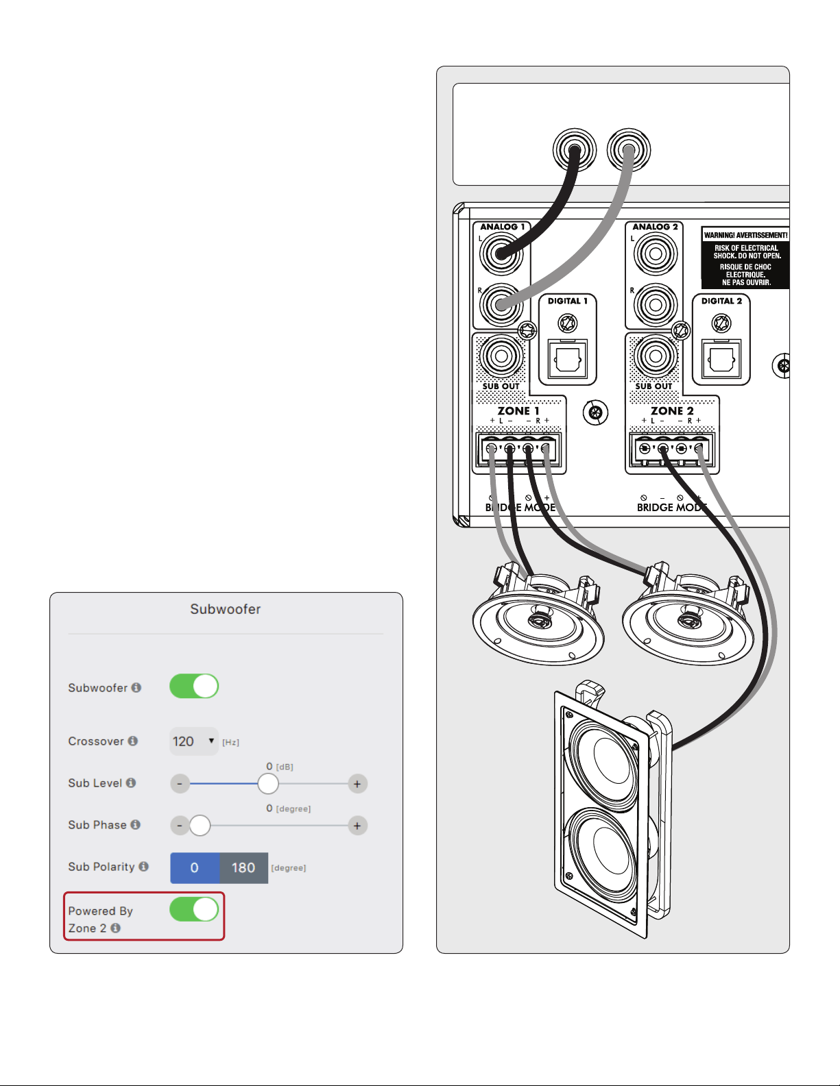
Powered by Zone 2 (4, 6, or 8): Congures two consecu-
tive zones to operate together for a stereo pair of speakers
and a dedicated passive subwoofer connected in bridge
mode (and must be connected as such on the rear pan-
el of the unit). When engaged, all adjustments are made
using the controls in the odd-numbered zone, and the
even-numbered zones controls are disabled. For example,
when engaged, Zone 1 controls both left and right speak-
ers connected to Zone 1 and the subwoofer connected to
Zone 2. Enable this feature before running ARC. See sec-
tion 3.7 for additional details.
The user interface design is subject to change.
14
Bulk Action: Use this when you want to change input
names without clicking apply after each change. Enter
names for all applicable inputs, select Check All from un-
der the Bulk Items drop-down, then select Apply from un-
der the Bulk Items drop-down.
Input Name: Assign a custom name for each input (up to
16 characters). You must click Apply to save this setting.
This name corresponds with the input list in the MDA’s user
interface. Please note, this does not necessarily change the
input name in associated control systems.
Trim: Adjusts the relative level of each input. Use this when
one input plays at a dierent level than the others, causing
changes in volume levels during playback while switching
between sources.
2.5 INPUTS SETTINGS
The user interface design is subject to change.
15
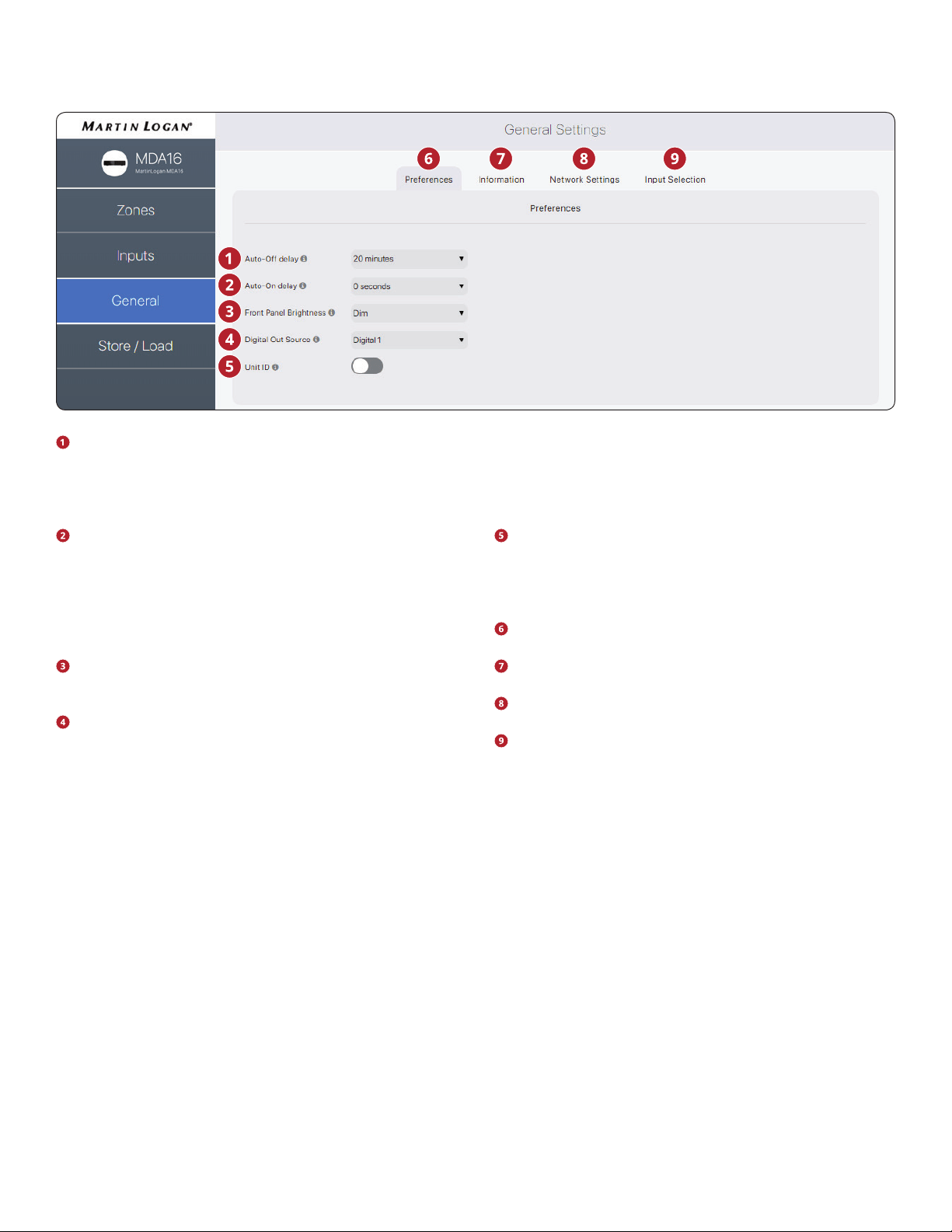
Auto-ODelay:Sets the length of time a zone waits to en-
ter standby mode after not receiving an audio signal. This
option only applies when you set the On Mode switch on
the back of the MDA to Auto.
Auto-On Delay: Sets the amount of time that the MDA
waits to power up when in standby. This delay is useful
when controlling multiple MDAs with a trigger, and you
want them to power on in a staged pattern. This option
only applies when you set the On Mode switch on the back
of the MDA to Auto or Trigger.
Front Panel Brightness: Sets the brightness of the front
panel LEDs.
Digital Out Source (MDA16 only): Allows you to select
which digital (optical or coaxial) to pass to the digital op-
tical output. This setting can be manipulated dynamically
through IP/RS232. Selecting an output in the user interface
does not prevent this setting from being changed through
IP or RS232.
Unit ID (Rear LED): Setting to On causes the ID light on the
back panel and the Power indicator on the front to blink.
This control is useful if you’re trying to identify a specic
MDA in a system with multiple MDAs.
General > Preferences: This section.
General > Information: See section 2.7.
General > Network Settings: See section 2.8.
General > Input Selection: See section 2.9.
2.6 GENERAL: PREFERENCES
The user interface design is subject to change.
16
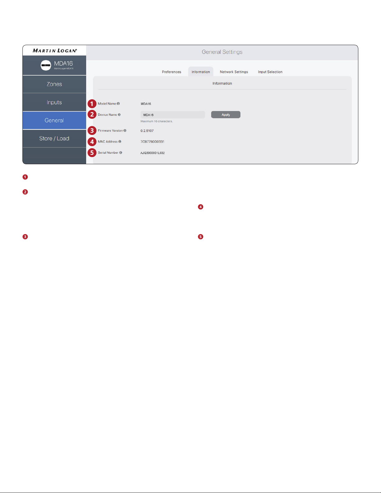
Model Name: Displays the MDA model.
Device Name: Assign a name to the MDA (up to 16 char-
acters) and click Apply to save this setting. The name of the
MDA appears in ARC allowing easy identication. Note that
the last few characters of the unit’s name correspond to
the end of the MAC address printed at the back of the unit.
Firmware Version: Displays the current rmware version
of the MDA. When connecting to the MDA’s web interface,
if there is an active internet connection, the MDA checks
our server and displays a notication at the bottom of the
screen if an update is available.
MAC Address: Displays the unique MAC address of the
MDA, which can be used to set a DHCP reservation in your
router.
Serial Number: Displays the unique serial number of the
MDA.
2.7 GENERAL: INFORMATION
The user interface design is subject to change.
17
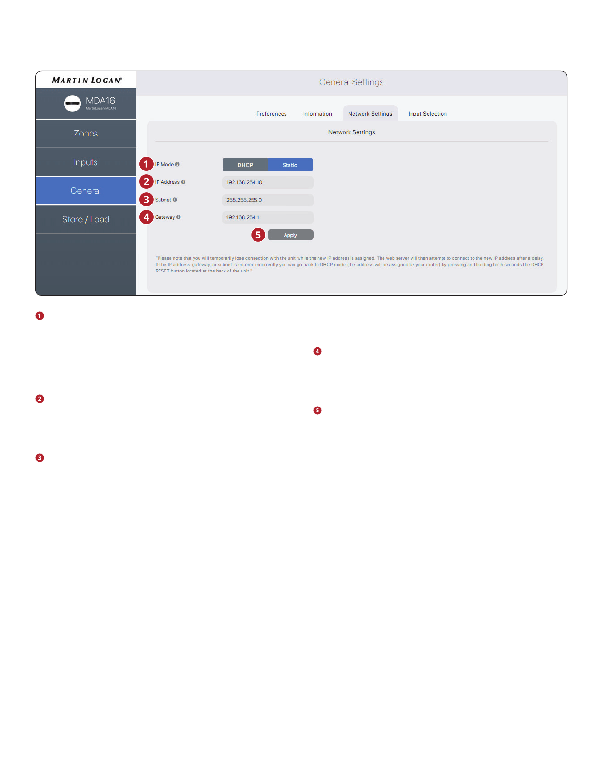
IP Mode: Toggles the MDA between DHCP and Static net-
work assignments. Changes take eect after clicking Ap-
ply. If errors occur when adjusting static IP settings, the
MDA can be manually set back to DHCP using the DHCP
Reset / Factory Image button located on the MDA’s back
panel (refer to troubleshooting).
IP Address: Displays the MDA’s current IP address. Adjust-
able if Static is selected. Changes take eect after clicking
Apply. Set new values for IP Address, Subnet, and Gateway
before clicking Apply.
Subnet: Displays the MDA’s current subnet mask. Adjust-
able if Static is selected. Changes take eect after clicking
Apply. Set new values for IP Address, Subnet, and Gateway
before clicking Apply.
Gateway: Displays the MDA’s current gateway address.
Adjustable if Static is selected. Changes take eect after
clicking Apply. Set new values for IP Address, Subnet, and
Gateway before clicking Apply.
Apply: Save the new network settings (if they have
changed). After clicking Apply, the MDA restarts a connec-
tion with the server and the web browser should automat-
ically attempt to reconnect to the new address.
2.8 GENERAL: NETWORK SETTINGS
The user interface design is subject to change.
18
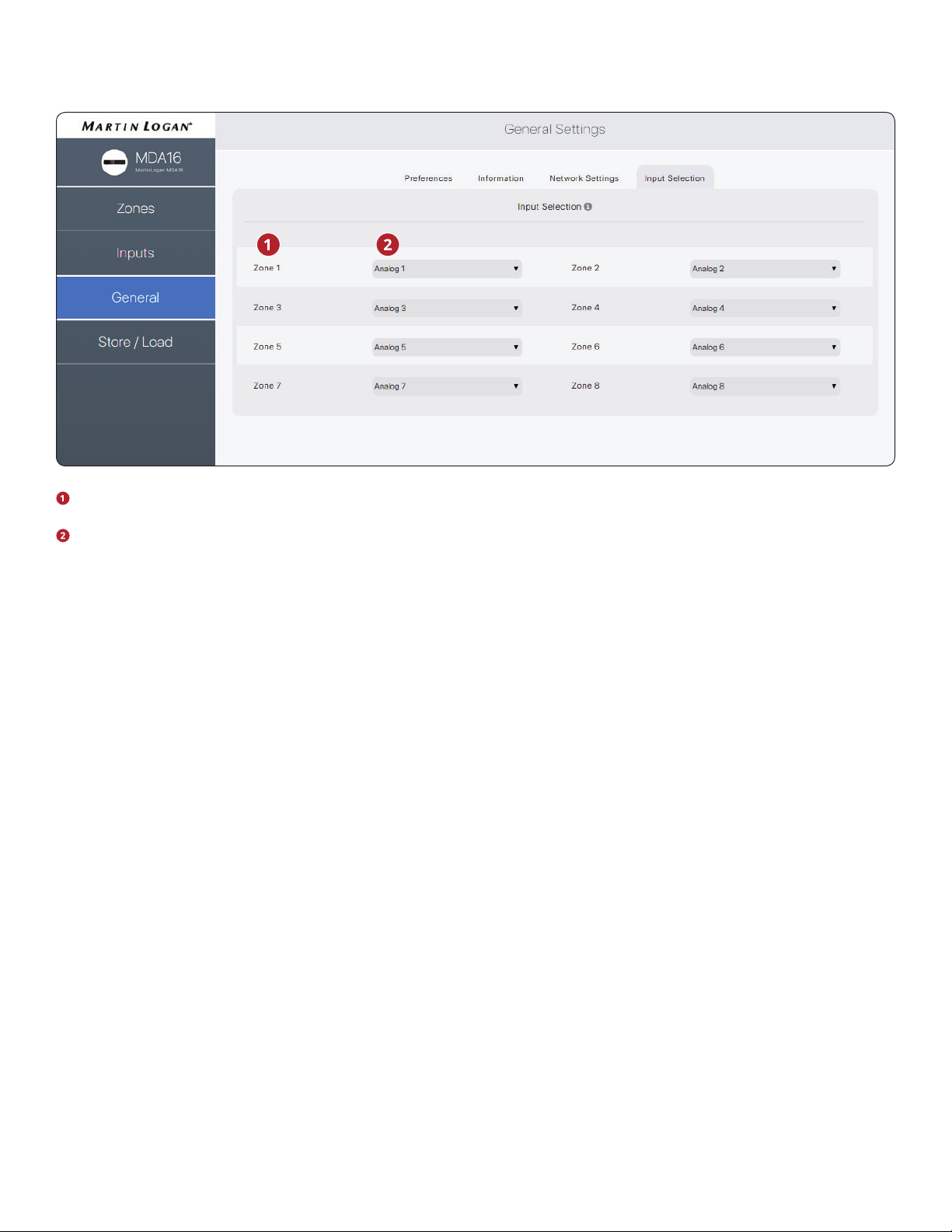
Displays the name assigned to each zone.
Displays the input playing in the zone and allows you to
reassign inputs. This control can be used to conrm that
the unit is appropriately responding to commands from a
3rd party automation system, or as an easy way to control
which inputs are playing in which zones.
2.9 GENERAL: INPUT STATUS
The user interface design is subject to change.
19
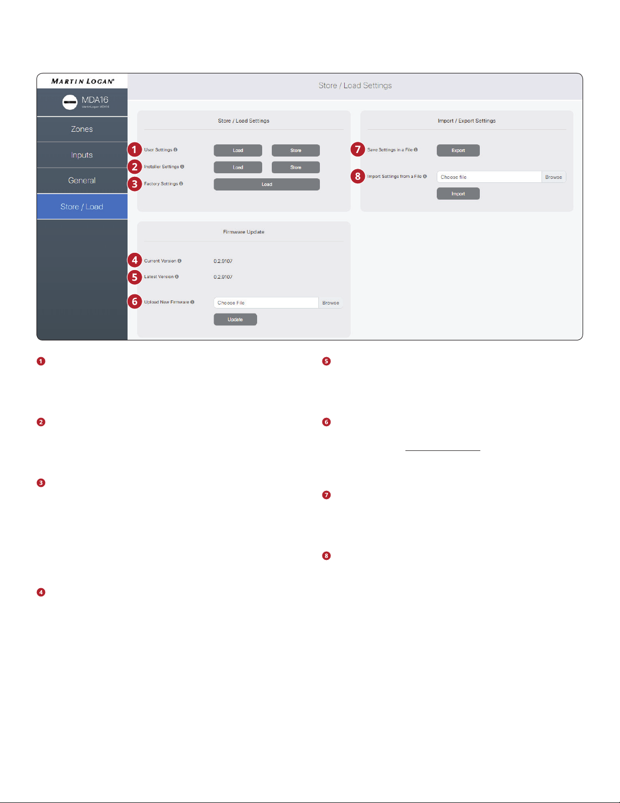
User Settings: Allows you to store the current settings to
the User Settings and load them back. The User Settings
are stored locally on the MDA and don’t require an exter-
nal le.
Installer Settings: Allows you to store the current settings
to the Installer Settings and load them back. The Installer
Settings are stored locally on the MDA and don’t require an
external le.
Factory Settings: Resets the current settings to the facto-
ry defaults. The saved user and installer settings remain
intact. It also erases ARC corrections (and turns ARC o) in
all zones. Loading the factory settings does not revert the
MDA rmware to the factory image. To revert the MDA to
the factory version of the rmware you need to use the
DHCP Reset / Factory Image reset button located on the
MDA’s back panel (refer section 7, Troubleshooting).
Current Version: Displays the current rmware version.
Latest Version: Displays the latest available rmware
version. If there is an active internet connection, the MDA
checks our servers and display a notication at the bottom
of the screen if an update is available.
Upload New Firmware: If the MDA does not have Inter-
net access, you can download the latest rmware from our
support page at MartinLogan.com. Click on Browse and se-
lect the le from your computer and then click on Update
to start the upgrade process.
Save Settings in a File: Saves a backup of the MDA’s cur-
rent settings on your computer, allowing you to copy set-
tings across MDA’s for a faster install, or if service is neces-
sary.
Import Settings from a File: Allows you to load previously
saved settings from an external le.
2.10 STORE/LOAD SETTINGS
The user interface design is subject to change.
20
3. CONNECTIONS AND BACK PANEL CONTROLS
3.1 LOCAL AREA NETWORK CONNECTION
A network connection is required to access the conguration
interface, run Anthem Room Correction, and use IP control.
Connect to your router using an Ethernet (CAT5) cable.
3.2 SPEAKER CONNECTIONS
Depending on the level of the input signal, the volt-
age at the outputs can be high enough to cause
electric shock – be sure that power is o when con-
necting or disconnecting anything. As well, be sure
to use speakers rated for use with this MDA – an
overdriven speaker can pose a re hazard.
MDAs oer several options for connecting speakers and pas-
sive subwoofers:
• Stereo speakers hooked to a single zone.
• For more power, a zone can be bridged to drive a single
speaker in either mono or stereo mode. Bridge mode uses
the left and right output to drive a single speaker. Mono
bridge mode uses a single zone whereas stereo bridge
uses two consecutive zones to drive a stereo pair.
• Bridge a zone to power a passive subwoofer to comple-
ment a stereo pair.
When stereo bridge is enabled, you must always use two con-
secutive zones (zones 1/2, 3/4, 5/6, or 7/ 8).
It is possible to mix-and-match zone congurations within a
single MDA. For example:
• Zone 1 (Kitchen): left & right speakers
• Zone 2 (Bathroom): left & right speakers
• Zones 3/4 (Den): left & right speakers bridged for more
power in stereo mode
• Zone 5/6 (Living Room): left & right speakers with a pas-
sive subwoofer (connected to Zone 6)
• Zone 7 (Hallway): left & right speakers bridged for more
power in mono mode
• Zone 8 (Bedroom): left & right speakers with a powered
subwoofer (connected via Zone 8 Sub Out RCA)
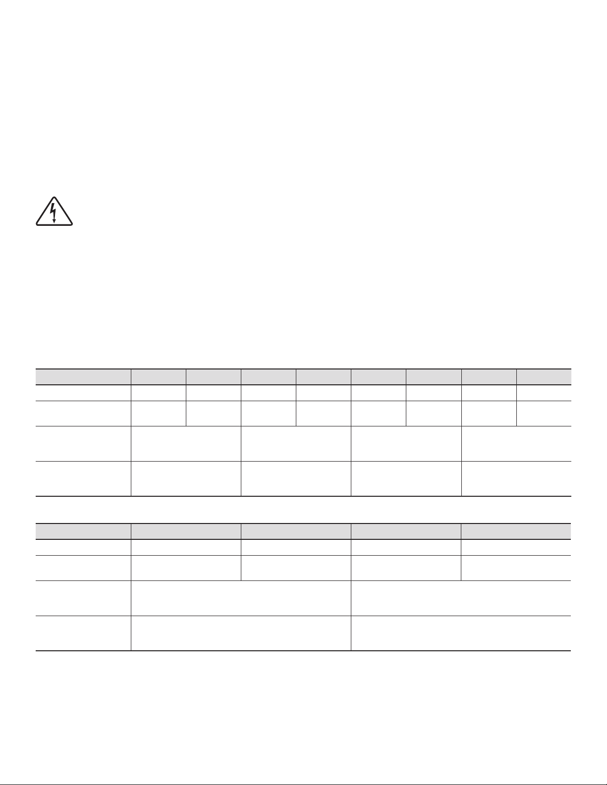
MDA16 Zone 1 Zone 2 Zone 3 Zone 4 Zone 5 Zone 6 Zone 7 Zone 8
Stereo Speakers Left & Right Left & Right Left & Right Left & Right Left & Right Left & Right Left & Right Left & Right
Mono Speaker Using
Mono Bridged Zone
Mono
(Left + Right)
Mono
(Left + Right)
Mono
(Left + Right)
Mono
(Left + Right)
Mono
(Left + Right)
Mono
(Left + Right)
Mono
(Left + Right)
Mono
(Left + Right)
Stereo Speakers
Using Two Bridged
Zones
Left (on zone 1)
Right (on zone 2)
[controlled via zone 1]
Left (on zone 3)
Right (on zone 4)
[controlled via zone 3]
Left (on zone 5)
Right (on zone 6)
[controlled via zone 5]
Left (on zone 7)
Right (on zone 8)
[controlled via zone 7]
Stereo Speakers and
Passive Subwoofer
Using a Bridged Zone
Left & Right (on zone 1)
Passive Sub (on zone 2)
[controlled via zone 1]
Left & Right (on zone 3)
Passive Sub (on zone 4)
[controlled via zone 3]
Left & Right (on zone 5)
Passive Sub (on zone 6)
[controlled via zone 5]
Left & Right (on zone 7)
Passive Sub (on zone 8)
[controlled via zone 7]
MDA8 Zone 1 Zone 2 Zone 3 Zone 4
Stereo Speakers Left & Right Left & Right Left & Right Left & Right
Mono Speaker Using
Mono Bridged Zone
Mono
(Left + Right)
Mono
(Left + Right)
Mono
(Left + Right)
Mono
(Left + Right)
Stereo Speakers
Using Two Bridged
Zones
Left (on zone 1)
Right (on zone 2)
[controlled via zone 1]
Left (on zone 3)
Right (on zone 4)
[controlled via zone 3]
Stereo Speakers and
Passive Subwoofer
Using a Bridged Zone
Left & Right (on zone 1)
Passive Sub (on zone 2)
[controlled via zone 1]
Left & Right (on zone 3)
Passive Sub (on zone 4)
[controlled via zone 3]
21
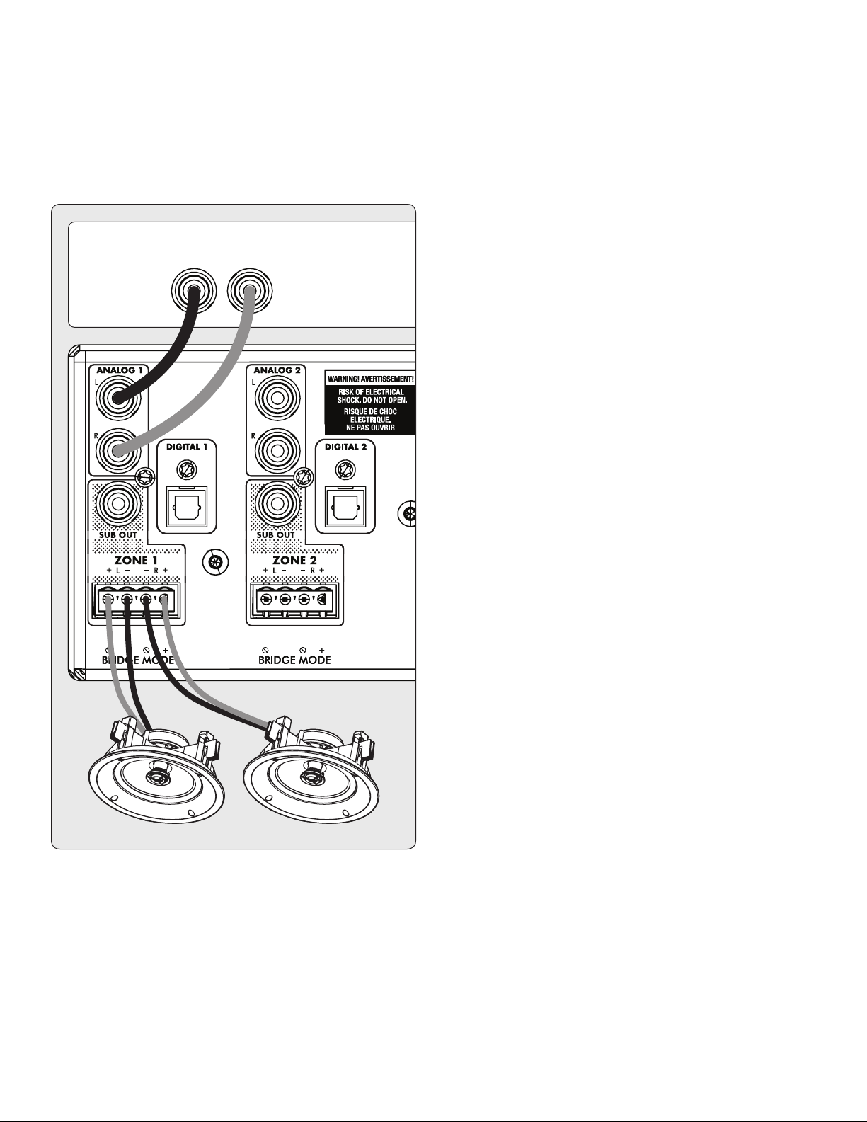
3.3 CONNECTING STEREO SPEAKERS
Connect a pair of speakers to a zone using a Euroblock (also
known as a Phoenix
TM
) connector. These connectors are in-
cluded with the MDA and come preinstalled. Euroblock con-
nectors accept speaker wire up to 12 gauge. Use speakers as
low as 4 Ohms in this conguration.
1. Remove the zone’s Euroblock connector from the MDA by
gently pulling it until it releases.
2. Use a small slotted screwdriver to loosen and tighten each
contact on the Euroblock when inserting the speaker wire.
3. Connect the red (+) connection on the left speaker to the
positive (L+) contact on the Euroblock connector as indi-
cated by the printing located on the MDA (above the con-
nector) or on the connector itself.
4. Connect the black (–) connection on the left speaker to
the negative (L–) contact on the Euroblock connector as
indicated by the printing located on the MDA (above the
connector) or on the connector itself.
5. Repeat for the right channel.
6. After attaching speaker wires to the Euroblock connector,
insert it into the MDA by gently pressing it into place.
ANALOG OUT
RL
LR
22
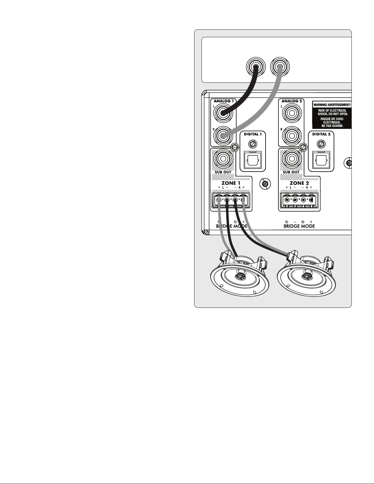
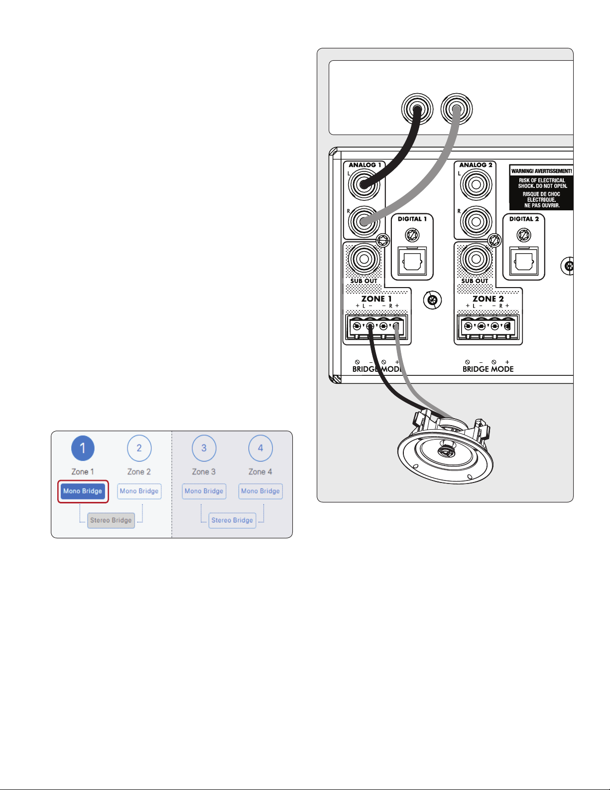
3.4 CONNECTING MONO SPEAKERS
USING ONE BRIDGED ZONE
A zone set to mono mode can be used to drive a single speak-
er, allowing the MDA to deliver more power per channel. En-
abling mono bridge sets the listening mode to mono automat-
ically. Bridge mode only supports speakers rated for 8 Ohms
or higher. Any zone set to Mono Bridge can use an active sub
connected via the zone’s Sub Out. An odd-numbered zone set
to Mono Bridge can use the matching even-numbered zone to
power a passive subwoofer using the Powered by Zone 2 (4,
6, or 8) setting.
Speaker Connection:
1. Remove the Euroblock connector by gently pulling it until
it releases.
2. Use a small slotted screwdriver to loosen and tighten each
contact on the Euroblock when inserting the speaker wire.
3. Connect the red (+) connection of the speaker to the pos-
itive (R+) contact on the Euroblock connector as indicated
by the printing located on the MDA (below the connec-
tor).
4. Connect the black (–) connection of the speaker to the
negative (L–) contact on the Euroblock connector as indi-
cated by the printing located on the MDA (below the con-
nector).
Enabling Bridge Mode:
1. Enable bridge mode via the web interface by going to
Zones and selecting Mono Bridge in the desired zone. The
Listening Mode is set automatically set to Mono.
ANALOG OUT
RL
L+R
23
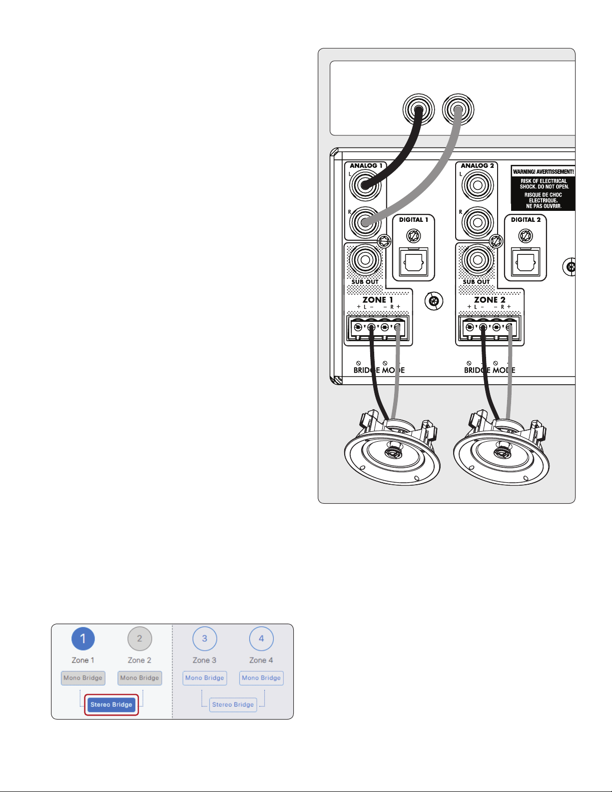
3.5 CONNECTING STEREO SPEAKERS
USING TWO BRIDGED ZONES
Using two zones to drive a single stereo pair of speakers allows
the MDA to deliver more power per channel. When bridging,
two consecutive zones are used to drive the stereo pair (Zones
1 and 2, 3 and 4, 5 and 6, or 7 and 8). Bridge mode only supports
speakers rated for 8 Ohms or higher. The only option to use a
subwoofer in this conguration is the use of an active sub con-
nected via Sub Out, and the MDA will no longer respond to IP or
RS232 commands for the even-numbered zone.
Left Speaker Connection:
1. Remove the Euroblock connector from the odd-num-
bered zone by gently pulling it until it releases. The left
speaker connects the odd zone.
2. Use a small slotted screwdriver to loosen and tighten each
contact on the Euroblock when inserting the speaker wire.
3.
Connect the red (+) connection of the left speaker to the pos-
itive (R+) contact on the Euroblock connector as indicated by
the printing located on the MDA (below the connector).
4.
Connect the black (–) connection of the left speaker to the neg-
ative (L–) contact on the Euroblock connector as indicated by
the printing located on the MDA (below the connector).
5. After attaching speaker wires to the Euroblock connector,
insert it into the MDA by gently pressing it into place.
Right Speaker Connection:
1. Repeat for the right speaker by making a similar connec-
tion on the next even zone (for example, if you just at-
tached the left channel to zone 1, connect the right speak-
er to zone 2).
2.
Connect the red (+) connection of the right speaker to the pos-
itive (R+) contact on the Euroblock connector as indicated by
the printing located on the MDA (below the connector).
3.
Connect the black (–) connection of the right speaker to the
negative (L–) contact on the Euroblock connector as indicated
by the printing located on the MDA (below the connector).
4. After attaching speaker wires to the Euroblock connector,
insert it into the MDA by gently pressing it into place.
Enabling Bridge Mode:
1. Enable bridge mode via the web interface by going to
Zones and selecting Stereo Bridge in the desired zone.
Controls for the even-numbered zone become unavail-
able, and the odd-numbered zone now controls settings
for both speakers.
ANALOG OUT
RL
LR
24
3.6 SUBWOOFER OUTPUTS
If you’re using this MDA to power a passive (non-powered)
subwoofer refer to the next section. To connect a powered
subwoofer, use an RCA cable, connect a zone’s Sub Out to a
powered subwoofer LFE input, and enable the subwoofer using
Zones > Subwoofer. If the powered subwoofer doesn’t have
an LFE input, connect to either the left or right input and set
the sub’s low-pass lter (commonly referred to as crossover) to
its highest or bypass setting. Please refer to your subwoofer’s
manual for specic connection and control setting instructions.
This control also enables the high pass lter on the left and
right outputs. If you are not using ARC and do not have a sub-
woofer connected, you can enable this control and set the
crossover frequency. This will avoid overloading speakers that
don’t support a full-range signal.
ANALOG OUT
RL
LR
SUB
25
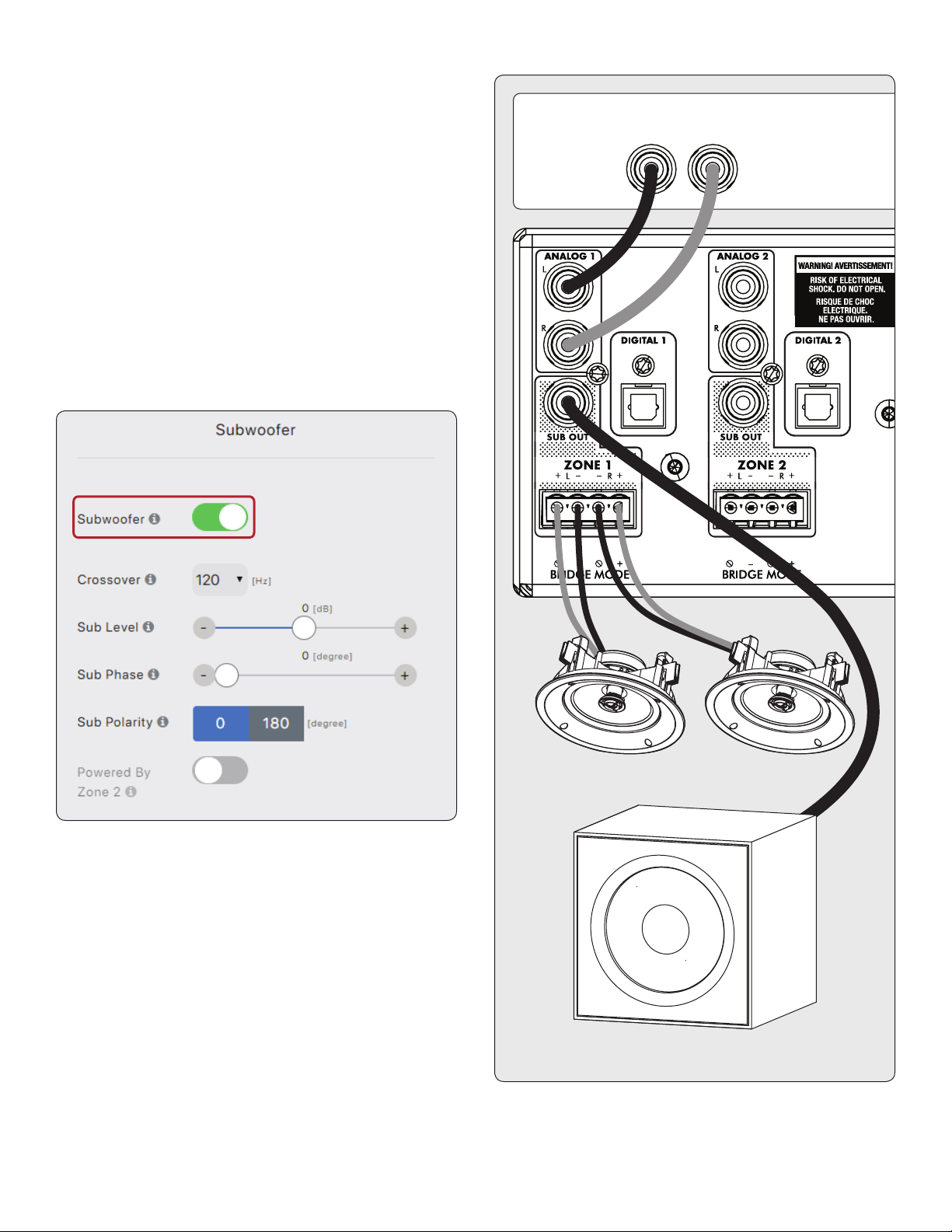
3.7 CONNECTING A PASSIVE
(NON-POWERED) SUBWOOFER
USING A BRIDGED ZONE
If using a passive (non-powered) subwoofer, an even-num-
bered zone can be congured to power the sub. This mode
only supports subwoofers rated at 8 Ohms or higher. The
even-numbered zone is bridged to provide more power. For
example, in Zone 1 connect the left/right speakers using the
stereo pair conguration and in Zone 2 connect the passive
subwoofer by following these instructions:
1. Remove the zone’s Euroblock connector from an even
zone of the MDA by gently pulling it until it releases.
2. Use a small slotted screwdriver to loosen and tighten each
contact on the Euroblock when inserting the speaker wire.
3. Connect the red (+) connection of the subwoofer to the
positive (R+) contact on the Euroblock connector as indi-
cated by the printing located on the MDA (below the con-
nector).
4. Connect the black (–) connection of the subwoofer to the
negative (L-) contact on the Euroblock connector as indi-
cated by the printing located on the MDA (below the con-
nector).
5. After attaching subwoofer wires to the Euroblock connec-
tor, insert it into the MDA by gently pressing it into place.
Using the web interface enable the subwoofer bridge mode in
the Zones > Subwoofer menu and then enable Powered by Zone
2 (4, 6, or 8). Note that the even zone parameters become un
-
available when this mode is enabled. The odd zone screen de-
termines the input source, level, crossover, phase, and polarity.
ANALOG OUT
RL
LR
SUB

26
3.8 DIGITAL INPUTS
Stereo digital audio sources can be connected using coaxial or
optical cables. The MDA16 has two digital optical inputs, and
two digital coaxial inputs and The MDA8 has one digital optical
input. All of these inputs support the PCM stereo format (up
to 24-bit / 192kHz). If using sources that have an option for
selecting between PCM and Bitstream (or Dolby Digital) audio
output, select PCM. If the source outputs a non-PCM stream
(such as a Dolby or DTS stream), the audio will mute.
3.9 DIGITAL OUTPUT (MDA16 ONLY)
The digital optical output on the MDA16 provides a repeat
function to feed an additional MDA (or any other component
that accepts digital optical input). This output supports up
to 24-bit/192kHz and can be congured to output any of the
MDA’s digital inputs (including digital coaxial). Select any of the
digital inputs via the web interface by clicking on Digital Out
Source in the General > Preferences screen and selecting the
appropriate digital input.
3.10 ANALOG INPUTS
Connect stereo analog sources using RCA cables. The MDA16
has eight stereo RCA line inputs. The MDA8 has four stereo
RCA line inputs.
3.11 ANALOG OUTPUTS (MDA16 ONLY)
The MDA16 has two stereo analog RCA line outputs. Any audio
source connected to the Analog 6 input passes unaltered to
the Analog 6 Out. Any audio source connected to the Analog
7 input passes unaltered to the Analog 7 Out. These act as
“pass-throughs” and work even when the MDA is in standby
or powered o.
3.12 POWER
Insert a power cord into the MDA’s AC input. Plug the cord into
a wall outlet. Ensure that the AC supply matches the voltage
rating shown on the back of the MDA. The 230V models sup-
port voltages from 220V to 240V.
3.13 TRIGGER CONNECTIONS
The trigger connection allows the MDA to be turned on or o
via the trigger input. When either Trig In 3.5mm (1/8”) mini-
jack receives power (5–24 volts DC or AC) from an upstream
component, the MDA turns on (Auto-On delay applies). When
it stops receiving power, the MDA turns o immediately. The
second Trig In jack allows you to run a cable out to daisy-chain
and trigger additional MDAs. For this function to work the On
Mode switch must be set to Trig. Please note, do not connect
triggers from two upstream components at the same time. Al-
ways use one as an input and one as an output.
The trigger also works with the On Mode switch set to Auto.
See section 3.15 for additional details.
3.14 RS-232 CONNECTION
The RS-232 connection allows connection to a compatible con-
trol system. The control system should be congured to use
115200/8-N-1, no ow control, protocol. The cable connection
should be one to one.
3.15 ON MODE SWITCH
With the three-way switch located on the back panel, you set
the way the MDA turns on and o.
• Trig: This sets the MDA to turn on and o when it receives
a signal on its Trig In connection. See section 3.13 for ad-
ditional details.
• Auto: This sets the MDA to turn on when it detects an in-
coming signal on any of its digital or analog audio inputs.
When the MDA stops detecting all incoming audio signals,
it enters standby mode after approximately 20 minutes
(by default). O and on times can be adjusted via the web
interface. Go to General > Preferences > Auto-O Delay
and Auto-On delay. The trigger input also works in this
mode. The MDA will turn on when a signal is applied to Trig
In, even if no audio signal is detected. The unit will enter
standby mode after the Auto-O delay once the trig signal
is removed and no audio signal is detected.
• Ext Cmd: This sets the MDA to ONLY turn on and o when
it receives commands from an IP or RS-232 control system.
Note that commands can be sent in any mode of operation.
For example, the volume may be changed whether the switch
is set to Auto or Trig. You will not be able to turn on a zone
using a command if in Trig mode and the trigger input is
de-asserted, but a turn on command will work if the On Mode
switch is set in Auto mode.
3.16 MASTER POWER SWITCH
This switch is wired directly to the AC mains and turns on and
o all power going to the MDA.
3.17 DHCP OR FACTORY IMAGE RESET
This reset button allows you to manually reset the MDA’s net-
work connection DHCP settings or restore the MDA to the
original factory image. See section 7 for additional details.
3.18 ID INDICATOR
When multiple MDAs are in a rack, you can quickly identify
each MDA by making use of the ID indicator. Use a web brows-
er to connect to the control interface of the rst MDA and en-
able Unit ID under General > Preferences. The ID light on the

27
back panel ashes as will the Power indicator on the front of
the MDA. You can also match the MAC Address shown under
General > Information with the unique MAC Address printed
on the back of each MDA.
3.19 ARC MICRO-USB CONNECTION
If a local area network connection is not available the Anthem
Room Correction (ARC) software can still connect to the unit
by making use of this micro-USB connector. Connect a USB
type A to micro B cable between the MDA and your PC or Mac.
3.20 CHASSIS GROUND
The MDA is powered using a double-insulated power cord and
therefore does not have an earth ground connection to avoid
hum. If an earth ground connection is required, or if connect-
ing to another chassis ground, you can connect a wire using
the thumbscrew.
3.21 FUSE
To replace the fuse, rst set the Master Power switch to O
and disconnect the power cord, Using a small slotted screw-
driver, remove the fuse cap and replace the fuse with a match-
ing type and rating as shown at the back of the unit.
28
4. ANTHEM ROOM CORRECTION (ARC
®
)
Please visit AnthemARC.com for detailed information about
using Anthem Room Correction.
The most signicant detriment to the sound of an audio sys-
tem is almost always the room it resides within—especial-
ly true in the realm of bass. Even in a professionally treated
sound room, bass can quickly become boomy or anemic. An-
them Room Correction helps audio systems sound their best
in any space. ARC oers a robust suite of tools to tame your
wild sonic frontier, whether you have a tricked-out home the-
ater, a traditional living room with carpet and thick drapes, or
a modern oor plan with large open spaces and acoustically
reective furniture and windows.
Have you ever tested the acoustics in an empty room by whis-
tling or clapping? It brings to mind how sound is aected by
a room’s size, structure, and contents. Even when using op-
timally positioned speakers of exceptional quality, the room
negatively impacts sound quality considerably. Surfaces such
as windows and furnishings and the geometry of the walls,
oor, and ceiling add unwanted resonance and coloration,
making the bass either boomy or less punchy, voices less nat-
ural, and the dialogue less intelligible. The eect on frequency
response is typically ±6 dB in the midrange and ±10 dB at low
frequencies.
To compensate for this and to optimize the in-room response
of your speakers, Anthem Room Correction measures the out-
put of each speaker relative to the listening area then, through
a series of calculations, adjusts its output. Not only does ARC
correct peaks and dips in a speaker’s frequency response, but
it also preserves the benecial acoustic attributes of a room—
attributes based on proven psychoacoustic science (the study
of how humans hear and experience sound).
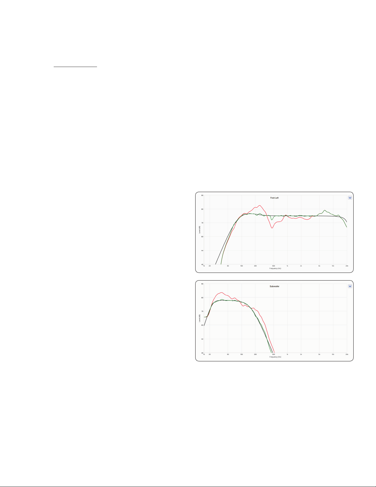
In the sample curves provided here, the red curves represent
the in-room response before correction, as an average from
ve measurement positions, whereas the green ones show re-
sponse with equalization applied. The black curve represents
the target response. In this case, a subwoofer and bass man-
agement are also in use.
The default correction range, as shown below, is 5,000 Hz.
This range can be changed to a higher or lower frequency if
desired, although raising it is not recommended. At higher fre-
quencies, the microphone becomes directional, thus aecting
measurement accuracy.
Note the rise in the measured and corrected response below
200 Hz. This rise shows the amount of room gain. ARC pre-
serves the natural room gain of the room or allows you to ad-
just the amount of room gain if you wish.
The subwoofer graph may imply that the subwoofer plays up
to the highest frequency shown, but what it plays depends
on what the other channels send to it as determined by their
crossover setting. The subwoofer graph shows the available
correction range, which is not necessarily the range that other
channels send to it through bass management.

29
4.1 USING ARC WITH AN MDA
In addition to correcting the acoustic response of subs
and speakers in each zone, ARC also:
• Adjusts the left/right balance of the speakers.
• Sets the crossover point between the speakers and sub-
woofer (do not manually change this after running ARC).
• Adjust the subwoofer’s level relative to the speakers.
• Sets the phase and polarity of the subwoofer relative to
the speakers (requires the additional step of running the
Automatic Phase Adjustment tool after uploading correc-
tions to the MDA).
Before using Anthem Room Correction:
• Name the MDA.
• Set up and name the zones.
• Enable subwoofers (if applicable).
To use Anthem Room Correction:
1. Download and install the program from AnthemARC.com.
2. Start the program and select Launch ARC from the rst screen.
3. Select the MDA from the device discovery screen.
4. Select the zone you wish to measure from the drop-
down list.
5. Follow the on-screen instructions to measure the zone,
calculate correction curves, and upload them to the MDA.
6. After uploading the corrections, run the Automatic Phase
Adjustment tool from the Review Summary & Upload
screen. This tool sets the phase of a subwoofer to opti-
mize its integration with the speakers.

30
5. UPDATING FIRMWARE
When connecting to the MDA’s web interface, the MDA checks
our server (if there is an active internet connection) and, if an
update is available, displays a notication at the bottom of the
screen. Alternatively, an update le can be downloaded from
our web site and installed later.
5.1 UPDATING FIRMWARE (USING AN
INTERNET CONNECTION)
1. Using a web browser on your computer, access the MDA’s
user interface.
2. The MDA automatically checks to see if there is a new rm-
ware version available and, if found, displays a prompt.
Click on Update Now to start the download and installa-
tion process.
5.2 UPDATING FIRMWARE (WITHOUT
AN INTERNET CONNECTION)
1. On MartinLogan.com, locate the software for your model.
Proceed if the version number on your MDA is lower than
the version shown on the website.
2. Save the .zip le to your desktop.
3. When the .zip le download completes, extract it to your
desktop.
4. Connect your computer and the MDA to a router.
5. Using a web browser on your computer, access the MDA’s
user interface, and navigate to Store / Load > Firmware
Update > Upload New Firmware.
6. Click Browse and select the le from your computer.
7. Click Update.
31
6. FAULT MODES
6.1 FRONT PANEL POWER LED
Power LED Status or Fault
Blue On
Red Network Standby
O Standby (no LAN connection) or no AC power
Red (ashing) Power on error (see section 6.3)
6.2 FRONT PANEL LAN LED
LAN LED Speed or Fault
Blue 100M
Red 10M
O No LAN connection
6.3 FRONT PANEL ZONE LEDS
Power
LED
Top
Zone LED
Bottom
Zone LED Status or Fault
Blue Blue O MDA enabled, no music detected.
Blue Normal operation: MDA enabled, music playing.
Blue
ashing
Blue Zone over temp. The module for a zone pair has exceeded a critical point, and the zone pair is turned o to protect the
module. After sucient cooling time (typically a few minutes) it will automatically resume normal operation if the system
is set to Auto or Trig mode. In Ext Cmd mode, a command is required to turn it back on.
Red
ashing
Zone overcurrent has been detected, either due to a low impedance speaker or a faulty speaker. The aected zone will
continue to ash its LEDs for at least 10 seconds. Normal operation will resume automatically if the overload is removed.
Blue
ashing
Zone thermal foldback. The MDA’s die (chip) temperature is approaching a critical point. The aected zone will continue
to ash its LEDs for at least 10 seconds. If this state is allowed to persist, the MDA will continue to operate but automati-
cally reduces the output level on that zone to protect itself.
Red Red
ashing
Red
ashing
High-frequency detect. The MDA detected an abnormal high-frequency signal on one of the speaker terminals and
shut down that zone to avoid damaging tweeters. The zone at fault will continue ashing its LED’s red. To clear this fault
condition, cycle the power by turning o AC power. Wait 1 minute before turning the MDA back on or until the front or
rear LAN jack LEDs go o. If the fault condition returns after a power cycle, the MDA requires service.
Red
ashing
O O PSU under voltage. This fault can be caused by:
• Inadequate AC line voltage
• Excessive power drawn by the combined zone outputs
• Failure of the PSU to reach operating voltage at power-up
For the rst two cases, normal operation resumes automatically in Auto and Trig mode, or by issuing a command when
in Ext Cmd mode. In the third case, an AC power re-cycle is required.
Blue
ashing
Blue
ashing
Power supply over temp. Total combined power output is excessive for the power supply. All zones are immediately
turned o, and all their LEDs will be ashing blue for a short period while the fan runs at high speed. Then the system will
power down and enter network standby. If in Auto or Trig mode, the system will automatically resume operation once it
has cooled suciently (normally several minutes). If in Ext Cmd mode a command is required to turn back on the unit.
Blue
ashing:
All zones
Red
ashing:
All zones
Software error. If there is an unrecoverable software error, all the LEDs on the top row will ash blue, and all the
bottom row will ash red. It can only be cleared by cycling power. Please note, when power cycling, turn the unit o for
a minute before turning it back on or until the front or rear LAN jack LEDs go o to make sure that all capacitors have
discharged.
Red
ashing:
All zones
Red
ashing:
All zones
PSU over voltage is detected. An AC power cycle is required to restart the system. Wait 1 minute before turning the
MDA back on or until the front or rear LAN jack LEDs go o. If the fault condition returns after a power cycle, the MDA
requires service.
Red
ashing:
Zone pair
Red
ashing:
Zone pair
DC Fault. The MDA detected an abnormal DC oset on one of the speaker terminals. The entire system shuts down
automatically to protect the speakers; the Zone at fault (and its twin) will continue ashing its LED’s red. To clear this fault
condition, cycle the power by turning o AC power. Wait 1 minute before turning the MDA back on or until the front or
rear LAN jack LEDs go o. If the fault condition returns after a power cycle, the MDA requires service.
Red
ashing:
During
power-up
See text See text Initialization error has occured when the unit powered up. The Power LED will ash red and the front or rear LAN LED
will ash blue. The top and bottom LEDs for one of the zones will be ashing red to report the fault:
• Zone1(bothashingred):DSP failure
• Zone2(bothashingred):ADC failure
• Zone3(bothashingred):SPDIF receiver failure
• Zone4(bothashingred):DAC failure
To clear this fault condition, cycle the power by turning o AC power. Wait 1 minute before turning the MDA back on or
until the front or rear LAN jack LEDs go o. If the fault condition returns after a power cycle, the MDA requires service.

32
7. TROUBLESHOOTING
Manually Resetting Network IP Mode to DHCP
If errors occur when adjusting static IP settings, the MDA can
be manually set back to DHCP. Using a pin or straightened
paperclip, depress the DHCP Reset / Factory Image button for
about 1 second. The blue ID LED turns on to indicate the se-
lection of DHCP. It should take a few seconds for the server to
reassign an address.
Manually Loading the Factory Image
This function restores the MDA to its original factory image.
Any rmware updates you have done are lost and replaced by
the version programmed at the factory. The current settings,
the saved user settings, and the saved installer settings are
deleted and replaced by the factory default. ARC corrections
are also erased from local memory.
To reload the original factory image and remove all settings, set
the Master Power switch to O and wait until the lights above
the Network connection stop ashing (this may take over a
minute if the unit was in standby). Using a pin or straightened
paper clip depress and hold the DHCP Reset / Factory Image
button while turning On the Master Power switch. Continue
to depress the button until the blue ID LED ashes twice. The
Factory Image reloads (this takes about a minute). Front panel
indicators turn blue and red using a chasing pattern while the
reload is taking place.

33
8. FREQUENTLY ASKED QUESTIONS
HowdoIndtheIPaddressofmyMDA?
We recommend using Anthem’s ARC Genesis software or us-
ing a utility called Fing. See section 2.2 for additional details.
I’m connecting my DVD player to the MDA using a TOS in-
put, but even if the disc is playing, I do not hear any sound.
The MDA digital input only supports a PCM stream. Access
your DVD player setup menu and change the output format
to PCM.
I have a subwoofer connected to the MDA using an RCA
jack, but even if I’m playing music with lots of low-fre-
quency content, the subwoofer does not work.
Enable the subwoofer (the default setting is o). See section
2.4 for additional information.
I’m sending commands to the MDA using the serial port,
but the MDA does not react.
Make sure to congure your controller to 115200/8-N-1. Make
sure to send the terminator “;” at the end of the command. CR/
LF are not required.
I’mconguringapairofspeakersinstereobridgemode
on zones 1 and 2. I have my left speaker on zone 1 and
my right speaker on zone 2. My source’s left channel is
attached to the Analog 1 left input and its right channel
connected to the Analog 2 right input. I only hear sound
fromtheleftchannel.WhatamIdoingwrong?
Inputs and speakers (even bridged speakers) operate inde-
pendently of one another. Attach your source’s left and right
channels to the Analog 1 inputs and set Zone 1’s Input Source
to Analog 1. When in bridge mode, Zone 1 becomes the “mas-
ter,” so source selection, volume change, tone control, are all
done by accessing the Zone 1 panel. All settings in Zone 2 set
before selecting Stereo Bridge mode are no longer relevant.
My CD player analog output level cannot be controlled
and defaults to a very high level (2 Vrms). When playing
music, the MDA seems to be clipping very often. How can
thisbeavoided?
The MDA allows you to change the trim of any source. Select
the Inputs pane and set the trim level between -6 dB to -9 dB
for the source where your CD player is connected.
How does the MDA work when the On Mode switch is set
toAuto?
When the MDA is in standby, it monitors all analog and digital
connectors to check if the unit needs to turn on:
• Analog connectors are monitored for a signal higher than
-60 dBV (1 mVrms).
• Digital connectors are monitored by checking if there
is any bit toggling on the coaxial or Toslink inputs. The
MDA doesn’t check for a specic level to achieve <1/2W in
standby, only activity.
When in operation, the active channels are monitored. When
the level drops below -60 dBV (for either analog or digital in-
puts) for the amount of time programmed in the Auto-O de-
lay, the zone turns o. If all zones are o, the unit will go in
standby.

34
9. SPECIFICATIONS
MDA8 MDA16
Warranty 3 years (parts and labor) 3 years (parts and labor)
Channels / Zones 8 channels / Up to 4 zones 16 channels / Up to 8 zones
Power Output RMS per Channel (8 Ohm) 60 Watts 60 Watts
Power Output RMS per Channel (4 Ohm) 120 Watts 120 Watts
High Output Mode (Bridged) RMS per
Channel (8 Ohm)
200 Watts 200 Watts
Frequency Response 10Hz – 20kHz ±0.5dB 10Hz – 20kHz ±0.5dB
THD + N (1 kHz at 50W into 8
Ohms/100W into 4 Ohms)
<0.4% / <0.4% <0.4% / <0.4%
Digital-to-Analog Converter PCM up to 24-bit/192kHz PCM up to 24-bit/192kHz
Inputs (analog) 4x RCA pairs (left & right) 8x RCA pairs (left & right)
Inputs (digital S/PDIF) 1x optical (Toslink) 2x RCA coaxial; 2x optical (Toslink)
Inputs (network) RJ-45 10Base-T/100Base-TX ethernet port (female) RJ-45 10Base-T/100Base-TX ethernet port (female)
Inputs (other) Micro-USB (for ARC); RS-232 Micro-USB (for ARC); RS-232
Input (trigger) 1x 3.5mm (5 – 24V DC/AC) 1x 3.5mm (5 – 24V DC/AC)
Outputs (speaker level) 4x removable Euroblock style (left & right)
accommodates wire up to 12AWG
8x removable Euroblock style (left & right)
accommodates wire up to 12AWG
Output (analog) — 2x RCA pair (left & right)
Outputs (subwoofer) 4x RCA (with bass management and room correction)
8x RCA (with bass management and room correction)
Outputs (digital matrix) — 1x optical (Toslink)
Output (trigger) 1x 3.5mm (5 – 24V DC/AC) 1x 3.5mm (5 – 24V DC/AC)
Audio In-Out Matrix Yes Yes
Advanced Load Monitoring Yes Yes
Controls (via web-based UI) Bass Level: ±10dB for each zone
Treble Level: ±10dB for each zone
Level Balancing: ±12dB for each zone
Bass Level: ±10dB for each zone
Treble Level: ±10dB for each zone
Level Balancing: ±12dB for each zone
Controls (back panel) Power Mode: Auto, Trigger, External Command
Network Reset (pinhole)
Factory Reset (pinhole)
Mains Power: On/O
Power Mode: Auto, Trigger, External Command
Network Reset (pinhole)
Factory Reset (pinhole)
Mains Power: On/O
Room Correction Anthem Room Correction (ARC) for each zone Anthem Room Correction (ARC) for each zone
Microphone (for room correction) Included dual-input microphone (3.5mm and
mini-USB)
Included dual-input microphone (3.5mm and
mini-USB)
Setup Web-based user interface Web-based user interface
IP Control (via IP or RS-232) Drivers for Control4, Crestron, Elan, RTI, Savant,
and URC
Drivers for Control4, Crestron, Elan, RTI, Savant,
and URC
AC Voltage (model dependent) 120V ±10% ~50/60Hz
220-240V ±10% ~50/60Hz
120V ±10% ~50/60Hz
220-240V ±10% ~50/60Hz
Operational Temperature 32° F to 113° F (0° C to 45° C) 32° F to 113° F (0° C to 45° C)
Storage Temperature Range -22° F to 158° F (-30° C to 70° C) -22° F to 158° F (-30° C to 70° C)
Humidity Range 5% to 95% non-condensing 5% to 95% non-condensing
Rack Mount Ears & Feet Included Included
Rack Space (feet removed) 2U 2U
Dimensions (H x W x D, without feet,
rack mount ears mounted, speaker
terminal blocks installed)
3.5” x 19.0” x 17.0”
(8.9 x 48.3 x 43.2 cm)
3.5” x 19.0” x 17.0”
(8.9 x 48.3 x 43.2 cm)
Dimensions (H x W x D, with feet, no
rack mount ears, speaker terminal
blocks installed)
3.9” x 17.0” x 17.0”
(9.9 x 43.2 x 43.2 cm)
3.9” x 17.0” x 17.0”
(9.9 x 43.2 x 43.2 cm)
Weight 21 lbs. (9.5kg) 24 lbs. (10.8kg)
Specications are subject to change.

35
10. LIMITED WARRANTY
SERVICE
Should you be using your MartinLogan product in a country
other than the one in which it was originally purchased, we ask
that you note the following:
1. The appointed MartinLogan distributor for any given
country is responsible for warranty servicing only on units
distributed by or through it in that country in accordance
with its applicable warranty.
2. Should a MartinLogan product require servicing in a coun-
try other than the one in which it was originally purchased,
the end user may seek to have repairs performed by the
nearest MartinLogan distributor, subject to that distribu-
tor’s local servicing policies, but all cost of repairs (parts,
labor, transportation) must be born by the owner of the
MartinLogan product.
3. If, after owning your MDA for six months, you relocate to
a country other than the one in which you purchased your
MDA, your warranty may be transferable. Contact Martin-
Logan for details.
WARRANTY INFORMATION
Thank you for purchasing a MartinLogan product. All MartinLogan
products meeting the conditions set forth here are eligible to
receive the Limited Warranty. Please retain your sales receipt for
proof of warranty terms and proof of purchase from an authorized
MartinLogan dealer or distributor in the United States or Canada.
Please register your purchase on the Online Warranty Registration
system (https://www.martinlogan.com/register) on MartinLogan.com.
Limited Warranty and Duration
MartinLogan, Ltd. warrants the product designated herein to be free
of manufacturing defects in material and workmanship, subject to
the conditions and for a period set forth below. This Warranty expires
on the anniversary of the date of delivery. The Limited Warranty peri-
od on MartinLogan products is as follows:
• Five (5) Years – Floorstanding, bookshelf, and on-wall speakers;
• Five (5) Years – On-wall, in-wall, and in-ceiling speakers;
• Three (3) Years – Powered subwoofers;
• Three (3) Years – Outdoor Living Series satellite speakers and sub-
woofers;
• Two (2) Years – Installer Series outdoor/all-weather speakers;
• Two (2) Years – Soundbars, separate power amplifiers and pre-am-
plifiers, and fully powered speakers;
• One (1) Year – Headphones.
How can you be sure to find a current authorized MartinLogan
Dealer?
Only dealers found on the following pages are current authorized
MartinLogan dealers. Goods purchased from any entity not found on
these lists list are not entitled to MartinLogan Limited Warranty cov-
erage:
• Authorized Online Dealers
https://www.martinlogan.com/locator
• Authorized United States Dealers
https://www.martinlogan.com/locator
• Authorized Canadian Dealers
https://www.martinlogan.com/locator
WhatisrequiredfortheLimitedWarrantyofMartinLoganproducts?
• Purchase of a new MartinLogan product from an authorized
MartinLogan dealer or distributor in the United States or Canada;
• A copy of the original receipt of sale from an authorized
MartinLogan dealer or distributor in the United States or Canada.
Limitations
• Warranty begins on the date of delivery;
• A copy of the original sales receipt from an authorized
MartinLogan dealer or distributor in the United States or Canada
is required for any warranty work;
• This Warranty is for the sole benefit of the original purchaser of
the covered product, is restricted to the original purchaser, and
requires the purchase of a new product;
• This warranty is not transferrable to a subsequent purchaser of
the product;
• Warranty applies to product in normal home use only. If product is
subjected to any conditions outlined in the next section, warranty is
void;
• Warranty does not apply if the product is used in professional or
commercial applications.
The Warranty is Void or Inapplicable if:
• The product was not purchased from an authorized MartinLogan
dealer or distributor in the United States or Canada;
• The serial number has been removed or defaced;
• The product has been used or handled other than in accordance
with the instructions in the owner’s manual;
• The product has been used in conjunction with unsuitable or
faulty equipment;
• The product has been abused or misused, damaged by accident
or neglect, or in being transported;
• The defect is due to the product being repaired or tampered with
by anyone other than MartinLogan or an authorized MartinLogan
repair center.

36
Owner Responsibilities:
• Provide normal/reasonable operating care and maintenance;
• Prior to returning a product to MartinLogan for repairs covered
by the Limited Warranty, the dealer from whom the speaker was
purchased should first be contacted to see if they can resolve the
issue;
• If a product is returned to MartinLogan for warranty work:
o The product must be properly packaged and shipped to
MartinLogan or an authorized MartinLogan repair center by
the customer at his or her sole expense;
o The product must be accompanied by an RMA number,
obtained from the MartinLogan service department (service@
martinlogan.com);
o The product must be accompanied by a written description
of the defect and proof of the date of purchase in the form
of a copy of the original sales receipt from an authorized
MartinLogan dealer or distributor.
Warranty Outside of the United States and Canada
This warranty applies only to purchases made from authorized
MartinLogan dealers and distributors in the United States and
Canada. For warranty terms, conditions, and support elsewhere,
please contact the authorized MartinLogan distributor in the coun-
try where your purchase was made. Warranty outside the US and
Canada is established and provided by authorized MartinLogan dis-
tributors around the world.
Refurbished Products Warranty Information
MartinLogan refurbished products may be lightly pre-owned, demon-
stration, test products, or factory closeouts that have undergone
rigorous inspection to ensure they meet MartinLogan’s strict quality
standards for both sonic performance and mechanical integrity. We
back every refurbished product with a Refurbished product warranty.
Our refurbished products are packaged in factory packaging, com-
plete with all documentation and where applicable, the accessories
that normally ship with the product. On occasion, refurbished prod-
ucts may contain minor cosmetic blemishes, but will sonically
perform to our industry leading full performance standards.
Each refurbished product:
• Has undergone rigorous inspections to ensure it meets our strict
quality standards.
• Is put through full testing to guarantee optimal sonic performance
and mechanical integrity.
• Is supplied with complete documentation.
• Is supplied with a one (1) year non-cosmetic warranty (Headphones
offer a 30 day warranty).
• Where applicable, is supplied with cables, remote control and
accessories.
• Where applicable, firmware is updated to the latest version.
• Is given a new refurbished serial number.
• Comes in factory product packaging with a “Refurbished” label.
• May have minor cosmetic blemishes.
Remedy
In the event the product fails during the warranty period and the
above conditions are met, the purchaser’s sole remedy under this
Warranty shall be to return the product to MartinLogan or an autho-
rized MartinLogan repair center where the defect will be rectified
without charge for parts or labor.
Conditions
MartinLogan reserves the right to modify the design of any product
without obligation to purchaser of previously manufactured products
and to change the prices or specifications of any product without
notice or obligation to any person.
Exclusions
Any implied warranties relating to the above product shall be limited
to the duration of the above Warranty. This Warranty does not extend
to any incidental or consequential costs or damages to the purchaser.
Some states do not allow limitations on how long an implied warran-
ty lasts or an exclusion or limitation of incidental or consequential
damages, so the above limitations or exclusions may not apply to you.
This Warranty gives you specific legal rights, and you may also have
other rights which vary from state to state. This Warranty represents
a limited warranty as per definition by the Federal Trade Commission
(Magnuson-Moss Act).

37
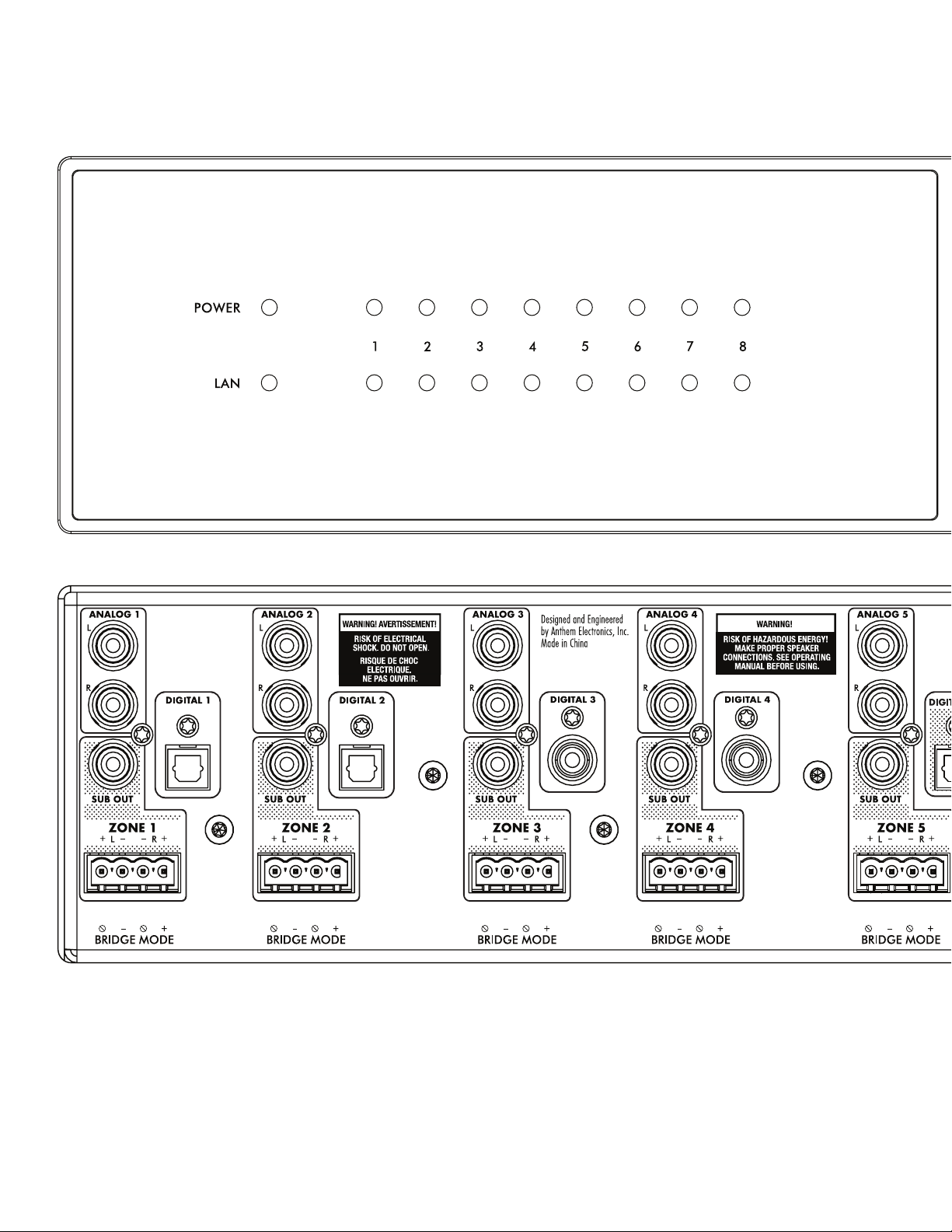
38
11. THE BIG PICTURE: MDA16
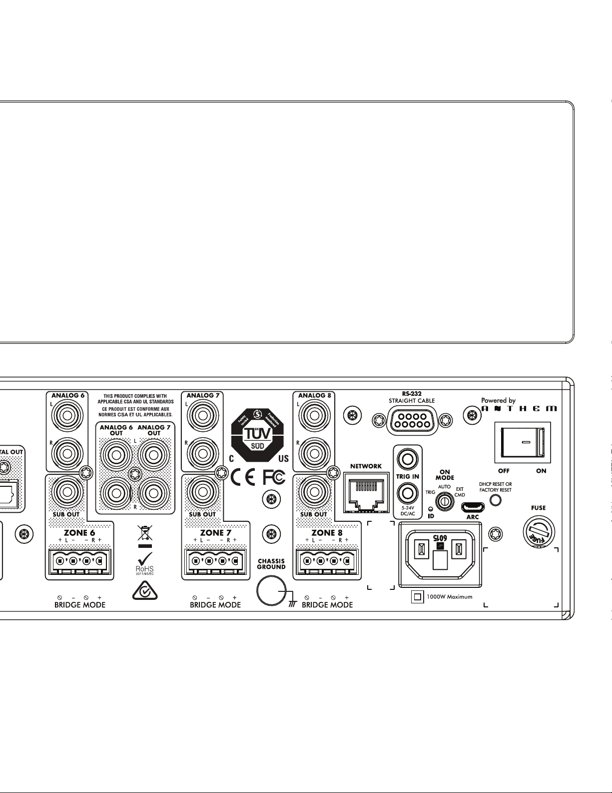
39
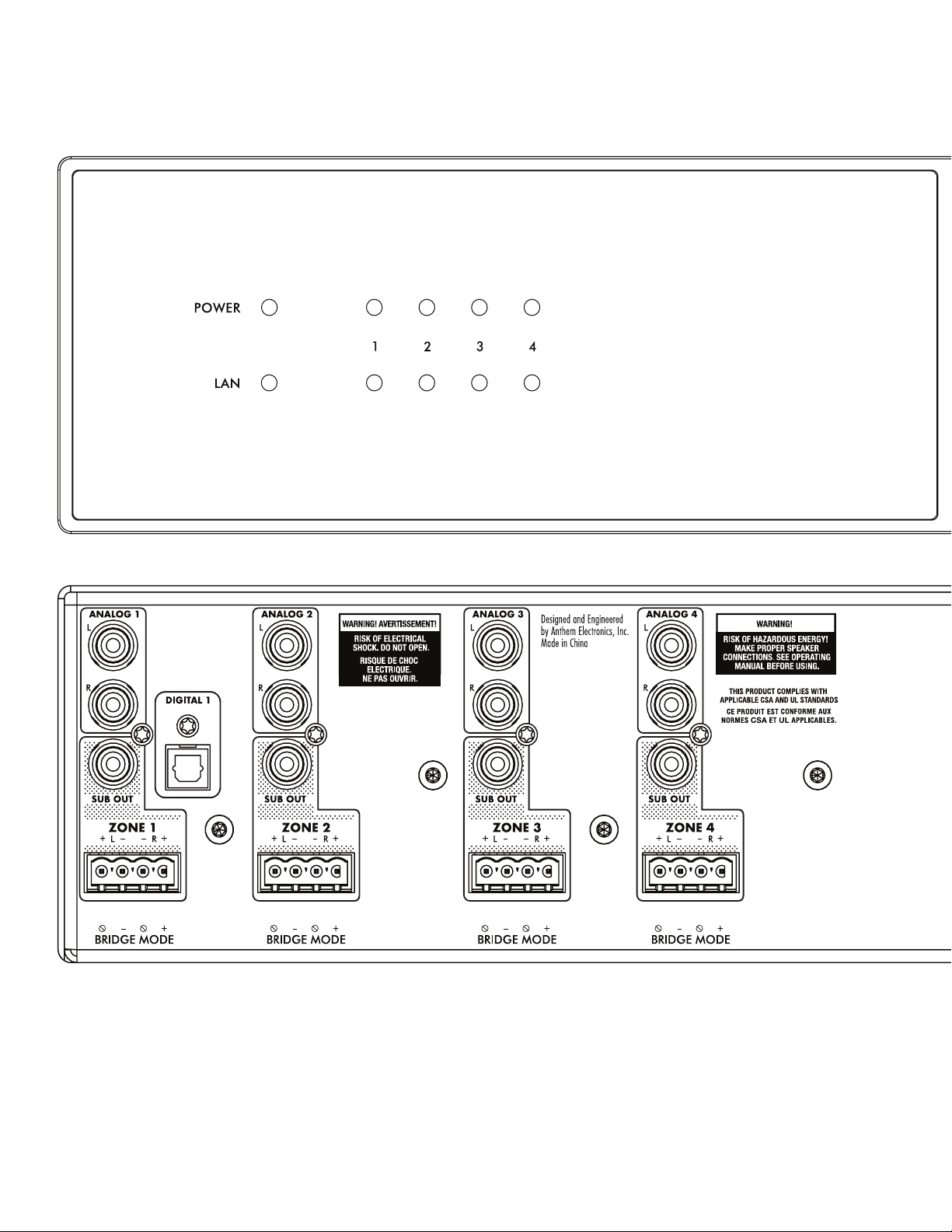
40
12. THE BIG PICTURE: MDA8
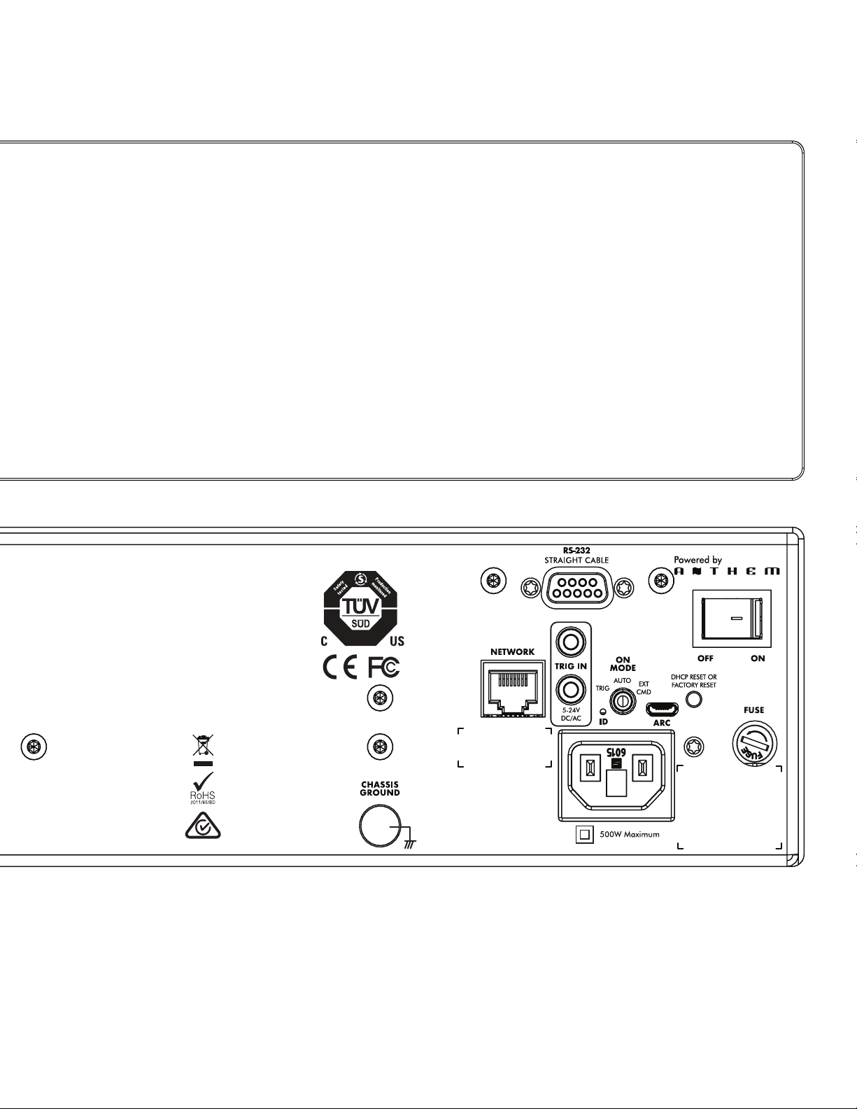
41

42
13. NOTES

43

Lawrence, Kansas, USA tel. 785.749.0133 fax 785.749.5320 www.martinlogan.com
©2019 MartinLogan Ltd. All rights reserved. Rev. #002
®