Loading ...
Loading ...
Loading ...
ENGLISH
8
ASSEMBLY AND ADJUSTMENTS
WARNING: To reduce the risk of serious personal
injury, turn unit off and disconnect it from
power source before making any adjustments or
removing/installing attachments or accessories.
An accidental start-up can causeinjury.
Assembly Instructions To Raise The Cutter
Head (Fig. B, C, D)
WARNING: To avoid injury, make sure all parts
are assembled and adjusted properly before
plugging the miter saw into a power outlet and
turning it ON.
1. Remove saw from the support base. Place saw with
blade and fence side facing up on a flat, stable surface.
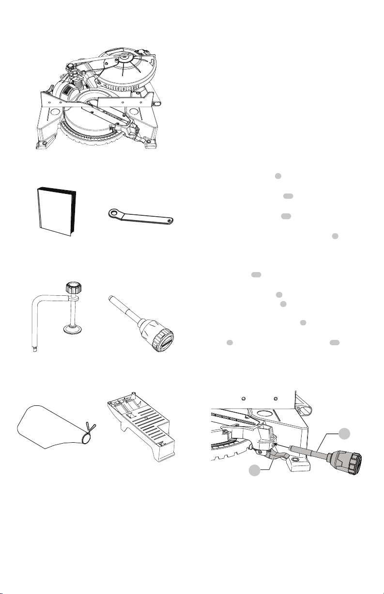
2. Thread the miter handle
7
into the hole located at the
front of the table as shown in Fig. B.
3. Loosen the bevel lock knob
12
located behind the base
as shown in Fig. C.
4. Pull out the safety lock pin
16
located next to the bevel
lock knob.
5. Grasp the cutting head by the switch handle
2
and
raise the cutting head up to the vertical position just
pass the 0° bevel setting.
6. Tilt the cutting head back to 0° and then tighten the
bevel lock knob
12
. The pin will automatically insert
into the slot, locking the head in position.
7. Loosen the miter handle
7
, grasp it and lift up the
positive stop locking lever
8
located under the miter
handle, to turn the table to 0° as shown on the miter
scale. Retighten the miter handle
7
.
8. Slightly push down the cutting head using the switch
handle
2
and pull out the hold-down latch
13
located
near the back on the left side of saw. This releases the
cutting head from the its locked position to swing
upward into operation position.
Fig.B
7
8
UNPACKING YOUR FOLDING MITER SAW
A
B C
D E
F G
Loading ...
Loading ...
Loading ...