final page size: 8.5 x 5.5 in CRAFTSMAN
10 in. (254 mm) Folding Compound Miter Saw
Sierra de inglete compuesta plegadiza de 254 mm
(10 pulgadas)
CMXEMAR120
INSTRUCTION MANUAL | MANUAL DE INSTRUCTIONES
IF YOU HAVE QUESTIONS OR COMMENTS, CONTACT US.
SI TIENE DUDAS O COMENTARIOS, CONTÁCTENOS.
1-888-398-7737 WWW.CRAFTSMAN.COM

English (original instructions) 1
Español (traducido de las instrucciones originales) 33
3
ENGLISH
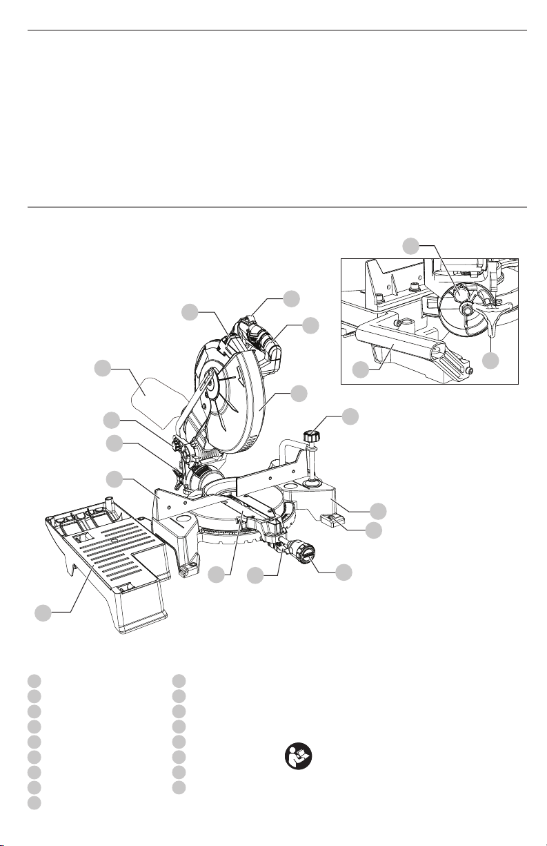
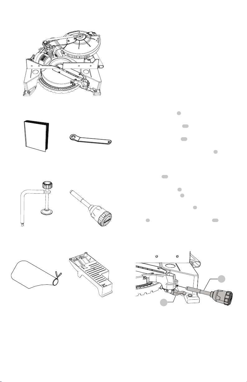
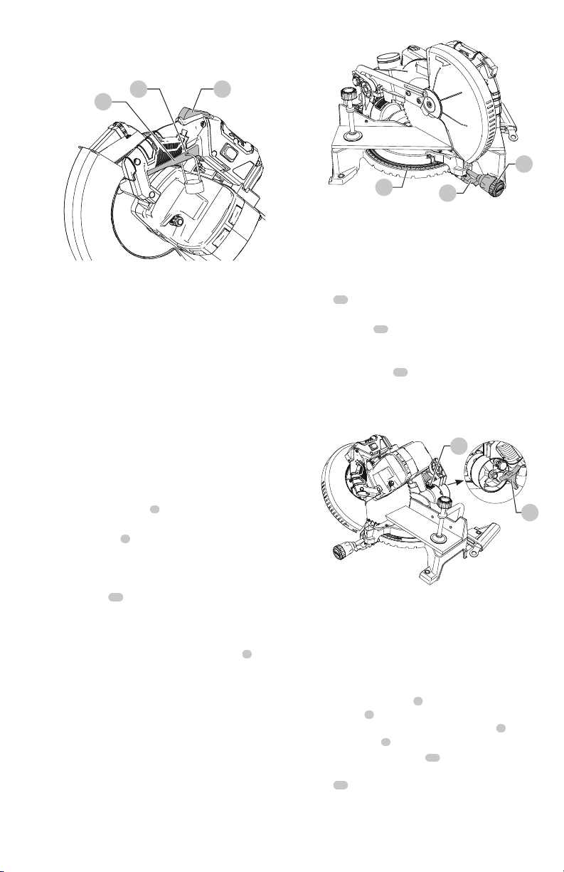
COMPONENTS
1
Safety lock
2
ON/OFF trigger switch handle
3
Lower blade guard
4
Hold-down clamp
5
Base
6
Mounting hole
7
Miter handle
8
Positive stop locking lever
9
Table insert
Fig. A
WARNING: Read all safety warnings and all
instructions. Failure to follow the warnings and
instructions may result in electric shock, fire and/or
seriousinjury.
WARNING: Never modify the product or any part of it.
Damage or personal injury couldresult.
WARNING: To reduce the risk of injury, read the
instructionmanual.
If you have any questions or comments about this
product, call CRAFTSMAN toll free at: 1-888-398-7737.
Definitions: Safety Alert Symbols and Words
This instruction manual uses the following safety alert symbols and words to alert you to hazardous situations and your risk
of personal injury or property damage.
DANGER: Indicates an imminently hazardous situation which, if not avoided, will result in death or seriousinjury.
WARNING: Indicates a potentially hazardous situation which, if not avoided, could result in death or seriousinjury.
CAUTION: Indicates a potentially hazardous situation which, if not avoided, may result in minor or moderateinjury.
(Used without word) Indicates a safety related message.
NOTICE: Indicates a practice not related to personal injury which, if not avoided, may result in propertydamage.
10
Support base
11
Fence
12
Bevel lock knob
13
Hold-down latch
14
Dust bag
15
Laser guide
16
Safety lock pin
17
Carrying handle
1
2
3
4
8
10
11
12
13
14
15
9
6
5
7
17
16
12
Rear view

ENGLISH
4
10 in. (254 mm) Folding Compound Miter Saw
CMXEMAR120
GENERAL POWER TOOL SAFETY WARNINGS
WARNING: Read all safety warnings,
instructions, illustrations and specifications
provided with this power tool. Failure to follow all
instructions listed below may result in electric shock,
fire and/or seriousinjury.
SAVE ALL WARNINGS AND
INSTRUCTIONS FOR FUTURE
REFERENCE
The term “power tool” in the warnings refers to your mains-
operated (corded) power tool or battery-operated (cordless)
powertool.
1) Work Area Safety
a ) Keep work area clean and well lit. Cluttered or dark
areas inviteaccidents.
b ) Do not operate power tools in explosive
atmospheres, such as in the presence of
flammable liquids, gases or dust. Power tools
create sparks which may ignite the dust orfumes.
c ) Keep children and bystanders away while
operating a power tool. Distractions can cause you
to losecontrol.
2) Electrical Safety
a ) Power tool plugs must match the outlet. Never
modify the plug in any way. Do not use any
adapter plugs with earthed (grounded) power
tools. Unmodified plugs and matching outlets will
reduce risk of electricshock.
b ) Avoid body contact with earthed or grounded
surfaces such as pipes, radiators, ranges and
refrigerators. There is an increased risk of electric
shock if your body is earthed orgrounded.
c ) Do not expose power tools to rain or wet
conditions. Water entering a power tool will increase
the risk of electricshock.
d ) Do not abuse the cord. Never use the cord for
carrying, pulling or unplugging the power tool.
Keep cord away from heat, oil, sharp edges or
moving parts. Damaged or entangled cords increase
the risk of electricshock.
e ) When operating a power tool outdoors, use an
extension cord suitable for outdoor use. Use of
a cord suitable for outdoor use reduces the risk of
electricshock.
f ) If operating a power tool in a damp location
is unavoidable, use a ground fault circuit
interrupter (GFCI) protected supply. Use of a GFCI
reduces the risk of electricshock.
3) Personal Safety
a ) Stay alert, watch what you are doing and use
common sense when operating a power tool. Do
not use a power tool while you are tired or under
the influence of drugs, alcohol or medication. A
moment of inattention while operating power tools
may result in serious personalinjury.
b ) Use personal protective equipment. Always wear
eye protection. Protective equipment such as dust
mask, non-skid safety shoes, hard hat, or hearing
protection used for appropriate conditions will reduce
personalinjuries.
c ) Prevent unintentional starting. Ensure the
switch is in the off position before connecting to
power source and/or battery pack, picking up or
carrying the tool. Carrying power tools with your
finger on the switch or energizing power tools that
have the switch on invitesaccidents.
d ) Remove any adjusting key or wrench before
turning the power tool on. A wrench or a key left
attached to a rotating part of the power tool may
result in personalinjury.
e ) Do not overreach. Keep proper footing and
balance at all times. This enables better control of
the power tool in unexpectedsituations.
f ) Dress properly. Do not wear loose clothing or
jewelry. Keep your hair, clothing and gloves
away from moving parts. Loose clothes, jewelry or
long hair can be caught in movingparts.
g ) If devices are provided for the connection of dust
extraction and collection facilities, ensure these
are connected and properly used. Use of dust
collection can reduce dust-relatedhazards.
h ) Do not let familiarity gained from frequent use
of tools allow you to become complacent and
ignore tool safety principles. A careless action can
cause severe injury within a fraction of a second.
4) Power Tool Use and Care
a ) Do not force the power tool. Use the correct
power tool for your application. The correct power
tool will do the job better and safer at the rate for
which it wasdesigned.
b ) Do not use the power tool if the switch does not
turn it on and off. Any power tool that cannot be
controlled with the switch is dangerous and must
berepaired.
c ) Disconnect the plug from the power source and/
or remove the battery, pack if detachable, from
the power tool before making any adjustments,
changing accessories, or storing power tools.
Such preventive safety measures reduce the risk of
starting the power toolaccidentally.

5
ENGLISH
d ) Store idle power tools out of the reach of children
and do not allow persons unfamiliar with the
power tool or these instructions to operate the
power tool. Power tools are dangerous in the hands
of untrainedusers.
e ) Maintain power tools and accesories. Check
for misalignment or binding of moving parts,
breakage of parts and any other condition
that may affect the power tool’s operation. If
damaged, have the power tool repaired before
use. Many accidents are caused by poorly maintained
powertools.
f ) Keep cutting tools sharp and clean. Properly
maintained cutting tools with sharp cutting edges are
less likely to bind and are easier tocontrol.
g ) Use the power tool, accessories and tool bits, etc.
in accordance with these instructions, taking
into account the working conditions and the
work to be performed. Use of the power tool for
operations different from those intended could result
in a hazardoussituation.
h ) Keep handles and grasping surfaces dry, clean
and free from oil and grease. Slippery handles and
grasping surfaces do not allow for safe handling and
control of the tool in unexpected situations.
5) Service
a ) Have your power tool serviced by a qualified
repair person using only identical replacement
parts. This will ensure that the safety of the
power tool is maintained.
SAFETY INSTRUCTIONS FOR MITER SAWS
• Miter saws are intended to cut wood or wood-like
products, they cannot be used with abrasive cut-off
wheels for cutting ferrous material such as bars,
rods, studs, etc. Abrasive dust causes moving parts such
as the lower guard to jam. Sparks from abrasive cutting
will burn the lower guard, the kerf insert and other plastic
parts.
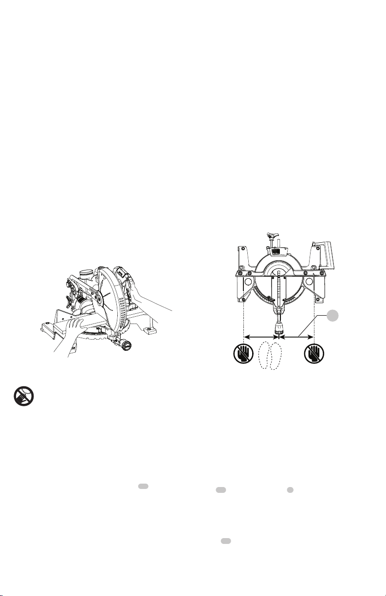
• Use clamps to support the workpiece whenever
possible. If supporting the workpiece by hand, you
must always keep your hand at least 100 mm from
either side of the saw blade. Do not use this saw to
cut pieces that are too small to be securely clamped
or held by hand. If your hand is placed too close to the
saw blade, there is an increased risk of injury from blade
contact.
• The workpiece must be stationary and clamped or
held against both the fence and the table. Do not
feed the workpiece into the blade or cut "freehand"
in any way. Unrestrained or moving workpieces could be
thrown at high speeds, causing injury.
• Push the saw through the workpiece. Do not pull the
saw through the workpiece. To make a cut, raise the
saw head and pull it out over the workpiece without
cutting, start the motor, press the saw head down
and push the saw through the workpiece.
Cutting on the pull stroke is likely to cause the saw blade
to climb on top of the workpiece and violently throw the
blade assembly towards the operator.
• Never cross your hand over the intended line of
cutting either in front or behind the saw blade.
Supporting the workpiece "cross handed" i.e. holding the
workpiece to the right of the saw blade with your left hand
or vice versa is very dangerous.
• Do not reach behind the fence with either hand
closer than 100 mm from either side of the saw
blade, to remove wood scraps, or for any other
reason while the blade is spinning. The proximity of
the spinning saw blade to your hand may not be obvious
and you may be seriously injured.
• Inspect your workpiece before cutting. If the
workpiece is bowed or warped, clamp it with the
outside bowed face toward the fence. Always make
certain that there is no gap between the workpiece,
fence and table along the line of the cut. Bent or
warped workpieces can twist or shift and may cause
binding on the spinning saw blade while cutting. There
should be no nails or foreign objects in the workpiece.
• Do not use the saw until the table is clear of all tools,
wood scraps, etc., except for the workpiece. Small
debris or loose pieces of wood or other objects that contact
the revolving blade can be thrown with high speed.
• Cut only one workpiece at a time. Stacked multiple
workpieces cannot be adequately clamped or braced and
may bind on the blade or shift during cutting.
• Ensure the miter saw is mounted or placed on a
level, firm work surface before use. A level and firm
work surface reduces the risk of the miter saw becoming
unstable.
• Plan your work. Every time you change the bevel or
miter angle setting, make sure the adjustable fence
is set correctly to support the workpiece and will
not interfere with the blade or the guarding system.
Without turning the tool "ON" and with no workpiece
on the table, move the saw blade through a complete
simulated cut to assure there will be no interference or
danger of cutting the fence.
• Provide adequate support such as table extensions,
saw horses, etc. for a workpiece that is wider or
longer than the table top. Workpieces longer or wider
than the miter saw table can tip if not securely supported.
If the cut-off piece or workpiece tips, it can lift the lower
guard or be thrown by the spinning blade.
• Do not use another person as a substitute for a table
extension or as additional support. Unstable support
for the workpiece can cause the blade to bind or the
workpiece to shift during the cutting operation pulling you
and the helper into the spinning blade.
• The cut-off piece must not be jammed or pressed
by any means against the spinning saw blade. If
confined, i.e. using length stops, the cut-off piece could get
wedged against the blade and thrown violently.

ENGLISH
6
• Always use a clamp or a fixture designed to properly
support round material such as rods or tubing. Rods
have a tendency to roll while being cut, causing the blade
to "bite" and pull the work with your hand into the blade.
• Let the blade reach full speed before contacting the
workpiece. This will reduce the risk of the workpiece being
thrown.
• If the workpiece or blade becomes jammed, turn
the miter saw off. Wait for all moving parts to stop
and disconnect the plug from the power source and/
or remove the battery pack. Then work to free the
jammed material. Continued sawing with a jammed
workpiece could cause loss of control or damage to the
miter saw.
• After finishing the cut, release the switch, hold the
saw head down and wait for the blade to stop before
removing the cut-off piece. Reaching with your hand
near the coasting blade is dangerous.
• Hold the handle firmly when making an incomplete
cut or when releasing the switch before the saw
head is completely in the down position. The braking
action of the saw may cause the saw head to be suddenly
pulled downward, causing a risk of injury.
• Do not use this saw to cut tree limbs or logs.
• Never use blades recommended for operation at less than
5000 RPM.
• Do not store materials on top of saw when in the
folded or unfolded position. Doing so could cause damage
to the lower guard.
• Do not hang this saw on a wall or other location.
• Do not pick up or carry this saw by the lower blade
guard. Doing so could cause damage to the guard.
• Do not use this saw to cut fiber cement board. This
saw is not intended to cut fiber cement board.
• Remove hold-down clamp from saw before folding and
transporting.
• Do not transport the unit standing up in a vehicle.
• Make sure power cord is wrapped up securely before
folding the saw for storage or transport.
WARNING: Additional warnings are listed
throughout this manual. Please review all before
operating this power tool.
PROPOSITION 65 WARNING
WARNING: Some dust created by power sanding,
sawing, grinding, drilling, and other construction
activities contains chemicals known to the State
of California to cause cancer, birth defects or
other reproductive harm. Some examples of these
chemicalsare:
• lead from lead-based paints,
• crystalline silica from bricks and cement and other
masonry products, and
• arsenic and chromium from chemically-
treatedlumber.
Your risk from these exposures varies, depending on
how often you do this type of work. To reduce your
exposure to these chemicals: work in a well ventilated
area, and work with approved safety equipment, such
as those dust masks that are specially designed to
filter out microscopicparticles.
Handling the power cord on this product may expose
you to chemicals known to the state of California to
cause cancer and birth defects or other reproductive
harm. Wash hands after handling.
For more information go to: www.P65Warnings.ca.gov
READ INSTRUCTION MANUAL: To reduce the risk of
injury, user and all bystanders must read instruction
manual before using this product.
• Avoid prolonged contact with dust from power
sanding, sawing, grinding, drilling, and other
construction activities. Wear protective clothing and
wash exposed areas with soap and water. Allowing
dust to get into your mouth, eyes, or lay on the skin may
promote absorption of harmfulchemicals.
WARNING: Use of this tool can generate and/
or disperse dust, which may cause serious and
permanent respiratory or other injury. Always use
NIOSH/OSHA approved respiratory protection
appropriate for the dust exposure. Direct particles
away from face andbody.
WARNING: Always wear proper personal hearing
protection that conforms to ANSI S12.6 (S3.19)
during use. Under some conditions and duration
of use, noise from this product may contribute to
hearingloss.
CAUTION: When not in use, place tool on its side on
a stable surface where it will not cause a tripping or
falling hazard. Some tools will stand upright but may
be easily knocked over.
• Air vents often cover moving parts and should be
avoided. Loose clothes, jewelry or long hair can be
caught in movingparts.
ELECTRICAL SPECIFICATIONS AND SAFETY
• An extension cord must have adequate wire size
(AWG or American Wire Gauge) for safety. The smaller
the gauge number of the wire, the greater the capacity
of the cable, that is, 16 gauge has more capacity than 18
gauge. An undersized cord will cause a drop in line voltage
resulting in loss of power and overheating. When using
more than one extension to make up the total length,
be sure each individual extension contains at least the
minimum wire size. The following table shows the correct
size to use depending on cord length and nameplate
ampere rating. If in doubt, use the next heavier gauge. The
lower the gauge number, the heavier thecord.
7
ENGLISH
Minimum Gauge for Cord Sets
Volts
Total Length of Cord in Feet
(meters)
120 V 25 (7.6) 50 (15.2) 100 (30.5) 150 (45.7)
240 V 50 (15.2) 100 (30.5) 200 (61.0) 300 (91.4)
Ampere Rating
American Wire Gauge
More
Than
Not
More
Than
0 6 18 16 16 14
6 10 18 16 14 12
10 12 16 16 14 12
12 16 14 12 Not Recommended
WARNING: Be sure your extension cord is
properly wired and in good condition. If it is not,
replace it with another cord. Do not use a damaged
extension cord. Protect your extension cords from
sharp objects, excessive heat and damp or wet areas.
The label on your tool may include the following symbols. The
symbols and their definitions are asfollows:
V ......................... volts
Hz .......................hertz
min ..................... minutes
or DC ......direct current
...................... Class I Construction
(grounded)
…/min ..............per minute
BPM .................... beats per minute
IPM ..................... impacts per minute
RPM .................... revolutions per
minute
sfpm ................... surface feet per
minute
SPM .................... strokes per minute
OPM .................... oscillations per
minute
A ......................... amperes
W ........................watts
or AC ...........alternating current
or AC/DC .... alternating or
direct current
...................... Class II
Construction
(double insulated)
n
o
.......................no load speed
n .........................rated speed
......................earthing terminal
.....................safety alert symbol
.....................visible radiation
..................... avoid staring at
light
..................... wear respiratory
protection
..................... wear eye
protection
..................... wear hearing
protection
SAVE THESE INSTRUCTIONS FOR
FUTURE USE
Motor
Be sure your power supply agrees with the nameplate
marking. Voltage decrease of more than 10% will cause loss
of power and overheating. These tools are factory tested; if
this tool does not operate, check power supply.
Intended Use
This miter saw is designed for wood cutting.
DO NOT use under wet conditions or in presence of
flammable liquids orgases.
This miter saw is a professional power tool. DO NOT let
children come into contact with the tool. Supervision is
required when inexperienced operators use thistool.
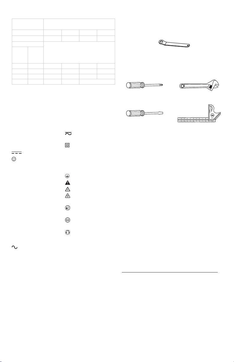
TOOLS NEEDED TO REMOVE OR INSTALL
BLADE
TOOLS NEEDED FOR ADJUSTMENT
CARTON CONTENTS
Unpacking And Checking Contents
Carefully unpack the miter saw and all its parts, and
compare against the list below and the illustration on the
next page. With the help of an assistant place the saw on a
secure surface and examine it carefully.
WARNING: To avoid injury from unexpected starting
or electrical shock, do not plug the power cord into
a source of power during unpacking and assembly.
The cord must remain unplugged whenever you are
adjusting/assembling the miter saw.
WARNING: The miter saw is heavy and should
be lifted with care. If needed, get the assistance of
someone to lift and move the miter saw.
WARNING: If any part is missing or damaged, do
not attempt to assemble the miter saw, or plug in
the power cord until the missing or damaged part is
correctly replaced.
Table of Loose Parts
ITEM DESCRIPTION Q’TY
A.
Miter saw
1
B.
Instruction manual
1
C.
Blade wrench
1
D.
Hold-down clamp
1
E.
Miter handle
1
F.
Dust bag
1
G.
Support base
1
Supplied
Blade wrench
Not supplied
Phillips Screwdriver
Slotted Screwdriver
Adjustable Wrench
Combination Square
ENGLISH
8
ASSEMBLY AND ADJUSTMENTS
WARNING: To reduce the risk of serious personal
injury, turn unit off and disconnect it from
power source before making any adjustments or
removing/installing attachments or accessories.
An accidental start-up can causeinjury.
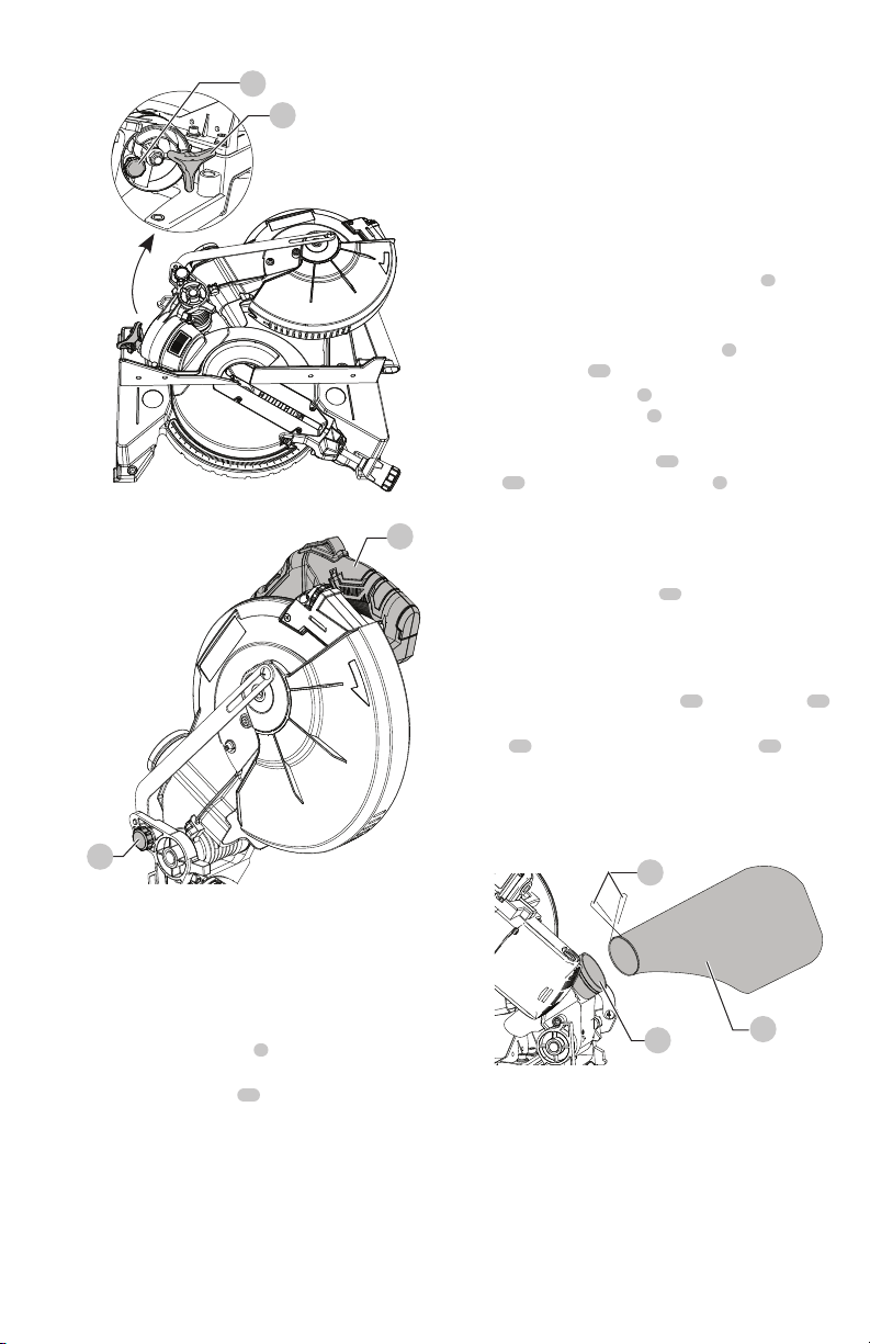
Assembly Instructions To Raise The Cutter
Head (Fig. B, C, D)
WARNING: To avoid injury, make sure all parts
are assembled and adjusted properly before
plugging the miter saw into a power outlet and
turning it ON.
1. Remove saw from the support base. Place saw with
blade and fence side facing up on a flat, stable surface.
2. Thread the miter handle
7
into the hole located at the
front of the table as shown in Fig. B.
3. Loosen the bevel lock knob
12
located behind the base
as shown in Fig. C.
4. Pull out the safety lock pin
16
located next to the bevel
lock knob.
5. Grasp the cutting head by the switch handle
2
and
raise the cutting head up to the vertical position just
pass the 0° bevel setting.
6. Tilt the cutting head back to 0° and then tighten the
bevel lock knob
12
. The pin will automatically insert
into the slot, locking the head in position.
7. Loosen the miter handle
7
, grasp it and lift up the
positive stop locking lever
8
located under the miter
handle, to turn the table to 0° as shown on the miter
scale. Retighten the miter handle
7
.
8. Slightly push down the cutting head using the switch
handle
2
and pull out the hold-down latch
13
located
near the back on the left side of saw. This releases the
cutting head from the its locked position to swing
upward into operation position.
Fig.B
7
8
UNPACKING YOUR FOLDING MITER SAW
A
B C
D E
F G
9
ENGLISH
WARNING: To reduce the risk of injury, turn unit off
and disconnect it from power source before installing
and removing accessories, before adjusting or when
making repairs. An accidental start-up can cause
injury.
WARNING: Make sure blade has stopped rotating
before folding the saw.
Folding The Cutting Head For
Transportation And Storage (Fig. B, C, D)
NOTE: Remove the hold-down clamp assembly
4
(Fig. F)
from saw before folding and transporting.
1. Keep the cutting head in the up position.
2. Slightly push down the switch handle
2
and push the
hold-down latch
13
into the locking hole.
3. Loosen the miter handle
7
, grasp it and lift up the
positive stop locking lever
8
to turn the turntable to the
right 55° and then tighten the miter handle.
4. Loosen the bevel lock knob
12
, pull out the safety lock
pin
16
and grasp the switch handle
2
to lower the
cutting head towards the right and down until hearing
a “click” sound.
NOTE: Make sure the cutting head is locked in position
and could not be moved.
5. Tighten the bevel lock knob
12
.
WARNING: DO NOT STORE MATERIALS ON TOP
OF SAW when in the folded or unfolded position.
Installing The Dust Bag (Fig. E)
1. Squeeze the metal collar wings
18
of the dust bag
14
.
2. Place the dust bag neck opening around the dust
port
19
, and release the metal collar wings
18
.
WARNING: Do not use this saw to cut and/or sand
metals. The hot chips or sparks may ignite sawdust
from the bag material.
Fig.E
Installing The Hold-Down Clamp Assembly
(Fig. F, G)
WARNING: CUTTING SMALL OR ROUND
MATERIAL, it should be cut just like wood and
CLAMPED OR HELD FIRMLY TO THE FENCE TO
KEEP IT FROM ROLLING. This is extremely important
when making angle cuts.
Fig.C
12
16
Fig.D
2
13
Locking The Cutting Head (Fig. B, C, D)
When not in use, the miter saw cutting head should always
be locked in the down position.
NOTE: Make sure the power cord is wrapped up securely
before folding the saw for storage or transport.
1. Pull down the switch handle
2
to place the cutting
head in its lowest position.
2. Push the hold-down latch
13
in.
IMPORTANT: To avoid damage, never carry the miter
saw by the lower blade guard, the switch handle, the
cutting head or the miter handle. ALWAYS use the
designated carrying handle.
WARNING: To reduce the risk of injury, you must
unplug the saw from power source before folding for
transportation or storage.
18
19
14
ENGLISH
10
1. Place the hold-down clamp assembly
4
into the
mounting hole
20
located behind the fence. The clamp
should be facing toward the back of the miter saw as
shown in Fig. F.
2. The groove on the clamp rod should be fully inserted
into the mounting hole of the base without being
visible. If the groove is visible, the clamp will not be
secure.
3. Rotate the hold-down clamp assembly
4
180 degrees
toward the front of the miter saw.
4. Loosen the knob
21
to adjust the clamp up or down to
firmly clamp the workpiece.
5. The hold-down clamp assembly
4
can be inserted in
one of the two mounting holes
20
located behind the
fence on either side of the base.
NOTE: Place the clamp on the opposite side of the
base when bevelling. ALWAYS MAKE DRY RUNS
(UNPOWERED) BEFORE FINISH CUTS TO CHECK THE
PATH OF THE BLADE. ENSURE THE CLAMP DOES
NOT INTERFERE WITH THE ACTION OF THE SAW OR
GUARDS.
Saw Blade
NOTE: The miter saw comes with the saw blade already
installed.
WARNING: Make sure the blade is installed correctly
and is tight before operating. See page 11 in
adjustments to tighten or remove the saw blade if
necessary.
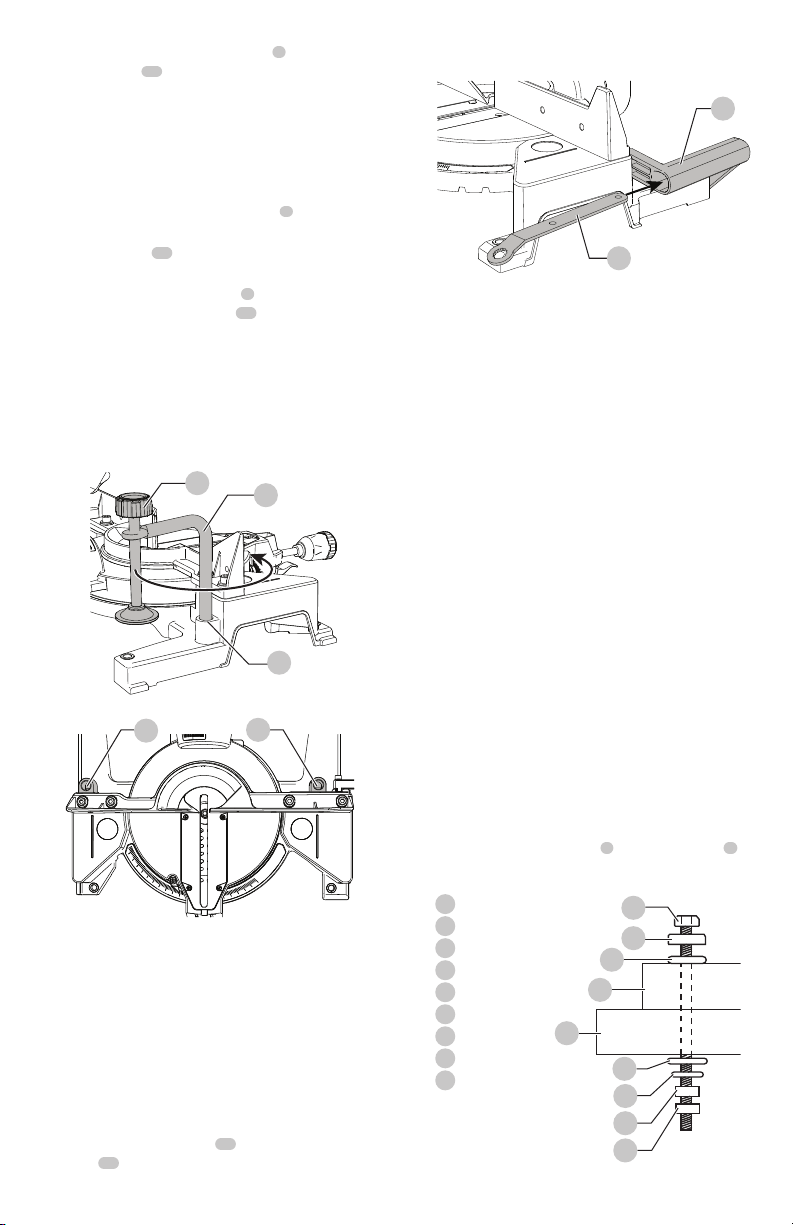
Saw Blade Wrench Storage (Fig. H)
1. For convenient storage and prevention of loss, there is
a slot in the carrying handle
17
for storing the blade
wrench
22
when not in use.
Fig.F
4
20
21
Fig.G
20
20
Fig.H
17
22
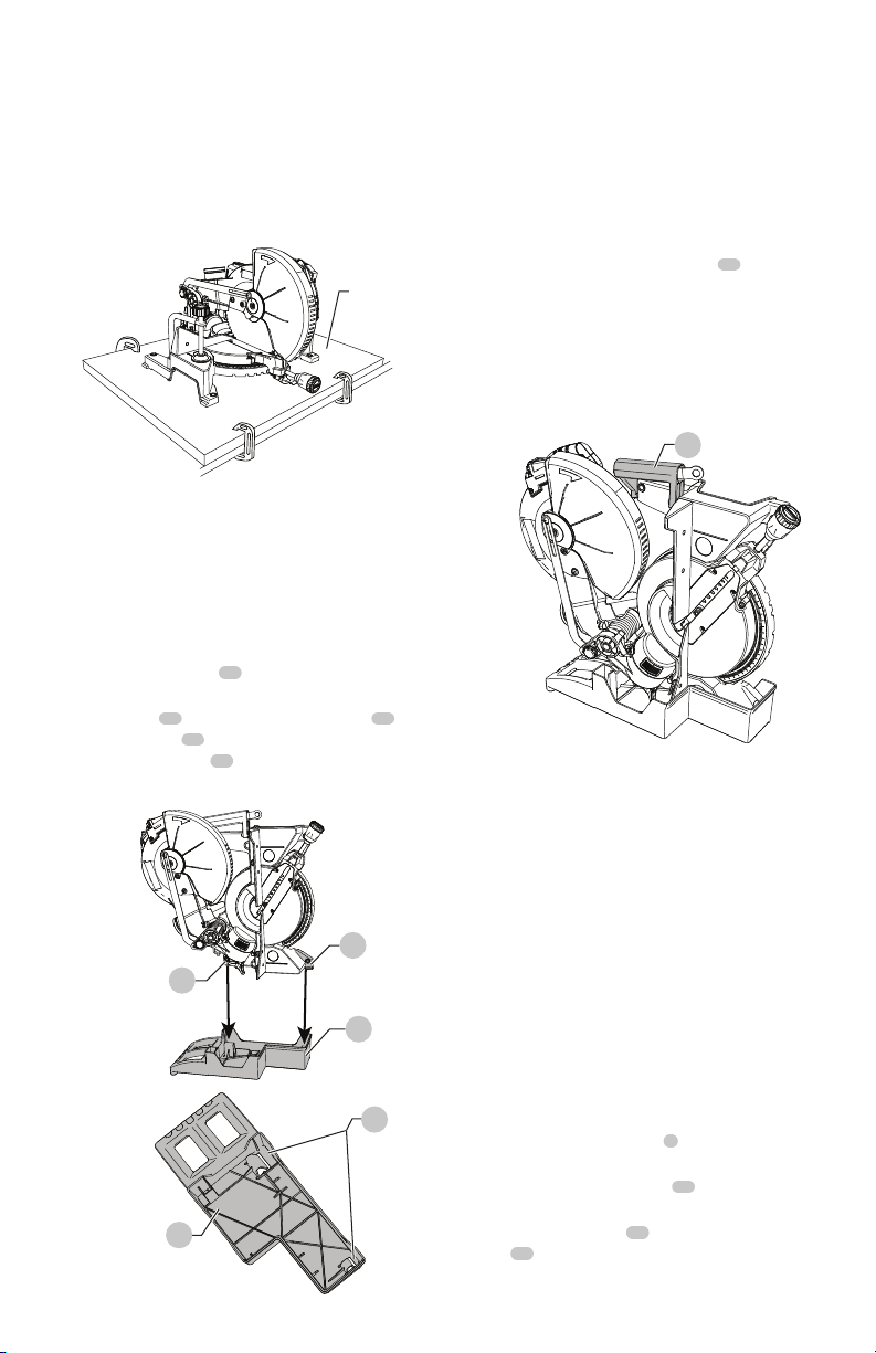
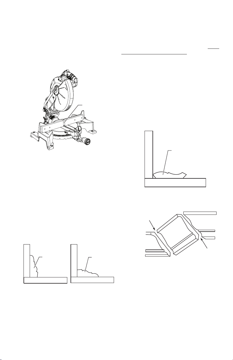
Mounting The Miter Saw (Fig. I, J)
WARNING: To avoid injury from unexpected saw
movement:
• Before moving the miter saw, disconnect the power cord
from the outlet, and lock the cutting arm in the lower
position using the hold-down latch.
NOTE: The hold-down latch is for carrying or storing
the tool. It is not to be used for holding the saw while
cutting. Lower the cutting head and press in hold-down
latch to secure the cutting head.
• Never carry the miter saw by the power cord or by the
trigger switch handle. Carrying the tool by the power cord
could cause damage to the insulation or wire connections
and result in electric shock or fire.
• To avoid injury from flying debris, do not allow visitors to
stand behind the saw.
• Place the saw on a firm, level workbench where there is
room for handling and properly supporting the workpiece.
• Support the saw on a level work surface.
• Bolt or clamp the saw to its support.
Mounting instructions:
1. For stationary use, place the saw in the desired location,
directly on a workbench where there is room for
handling and proper support of the workpiece. The base
of the saw has four 3/8 in. mounting holes. Select the
proper mounting holes based on the size of bolts used.
Bolt the base of the miter saw
a
to the workbench
b
,
using the fastening method as shown in Fig. I.
Fig.I
a
Miter saw base
b
Hex head bolt
c
Rubber washer
d
Flat washer
e
Workbench
f
Flat washer
g
Lockwasher
h
Hex nut
i
Jam nut
b
c
d
a
e
f
g
h
i
11
ENGLISH
NOTE: Mounting hardware is not included with this
tool. Bolts, nuts, washers, and screws must be purchased
separately.
2. For portable use, place the saw on a 3/4 in. thick piece
of plywood. Bolt the base of the miter saw securely to
the plywood using the mounting holes on the base. Use
C-clamps to clamp this mounting board to a stable work
surface at the worksite. (Fig. J)
NOTE: If a miter saw stand is used, please follow all
instructions shown in that product’s instructions for proper
mounting.
Using The Support Base (Fig. K)
1. Fold the miter saw. (See the section of “FOLDING THE
CUTTING HEAD FOR TRANSPORTATION AND STORAGE”
on page 9.)
2. Place the support base
10
on a flat surface or ground as
shown in Fig. K.
3. Align the feet
23
of the base with the grooves
24
of
the support base
10
and then insert the folded saw
into the support base
10
, so that the miter saw could
stand on the ground.
Fig.J
3/4 in.
plywood
Fig.K
23
23
10
10
24
FRONT
REAR
REAR FRONT
Transporting The Saw (Fig. L)
WARNING: To reduce the risk of serious personal
injury, ALWAYS lock the miter lock handle, bevel lock
knob, lock down pin before transporting saw.
NOTE: To avoid damage, never carry the miter saw by the
switch handle. To reduce the risk of serious personal injury,
ALWAYS secure all clamps, knobs, latches and locks before
lifting the saw.
1. Never carry the saw by the switch handle, miter clamp
or cutting head. The carrying handle
17
is appropriate
for when the saw is folded only. When saw is not folded,
the hand holds should be used.
2. ALWAYS use the support base when storing the saw
vertically.
WARNING: Do not transport the unit standing up in
a vehicle.
Removing And Installing The Blade
WARNING: Only use 10 inch diameter crosscut blades
on this saw. Do not use blades with deep gullets.
These can deflect and contact the guard, and can
cause damage to the machine and/or serious injury.
To avoid injury from an accidental start, make sure
the switch is in the OFF position and the plug is not
connected to the power source outlet.
NOTE: The miter saw comes with the saw blade
already installed.
WARNING: Make sure the blade is installed correctly
and is tight before operating.
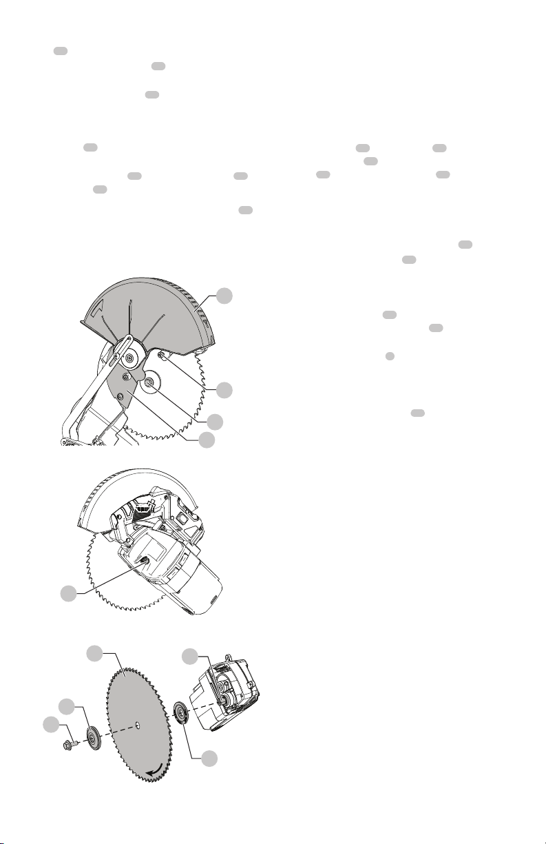
Removing the Blade (Fig. M, N, O)
1. Unplug the saw from the outlet.
2. Raise the cutting head to the upright position.
3. Raise the lower blade guard
3
to the uppermost
position. (Fig. M)
4. Loosen the cover plate screw
25
with a Phillips
screwdriver.
5. Rotate the cover plate
26
back to expose the arbor
bolt
27
.
Fig.L
17
ENGLISH
12
6. Place the provided blade wrench over the arbor
bolt
27
.
7. Locate the arbor lock button
28
below the trigger
switch handle. (Fig. N)
8. Press the arbor lock button
28
, holding it in firmly while
turning the blade wrench clockwise. This will engage
the arbor lock allowing the arbor bolt to be loosened
with the blade wrench. Continue to hold the arbor
lock button
28
while turning the wrench clockwise to
loosen the arbor bolt.
9. Remove the arbor bolt
27
, the outer blade collar
29
,
and the blade
30
. (Fig. O)
CAUTION: Do not remove the inner blade collar 31 .
NOTE: Pay attention to the pieces removed, noting their
position and direction they face. Wipe the blade collars
clean of any sawdust before installing a new blade.
Fig.M
3
25
26
27
Fig.N
28
Fig.O
27
29
30
Do not
remove
31
32
Installing the Blade (Fig. M, N, O)
WARNING: Un-plug the miter saw before changing/
installing the blade.
1. Install a 10 in. blade with a 5/8 in. arbor hole, making
sure the rotation arrow on the blade matches the
clockwise rotation arrow on the upper guard, and the
blade teeth are pointing downward at the front of the
saw.
2. Place the blade
30
onto the arbor
32
and against the
inner blade collar
31
. Then, place the outer blade
collar
29
and thread the arbor bolt
27
counterclockwise onto the arbor. (Fig. O)
IMPORTANT: The flat side of the blade collars must be
placed against the blade. Do not install the collars with
the curved side against the blade.
3. Place the blade wrench on the arbor bolt
27
.
4. Press the arbor lock button
28
, holding it in firmly while
turning the blade wrench counterclockwise. Continue
to press it in while tightening the arbor bolt securely.
(Fig. N)
5. Rotate the cover plate
26
back to its original position
and tighten the cover plate screw
25
with a Phillips
screwdriver. (Fig. M)
6. Lower the blade guard
3
back to its original position.
7. Pull the switch handle down and up several times
to confirm the lower blade guard operates without
binding.
8. Be sure the arbor lock button
28
is released so the
blade turns freely. (Fig. N)
WARNING: To avoid injury, never use the saw without
the cover plate secure in place. It keeps the arbor bolt
from falling out if it accidentally loosens, and helps
prevent the spinning blade from coming off the saw.
WARNING: If the cover plate is not secure in its proper
place, the guard may contact the spinning saw blade,
resulting in damage to the saw and severe personal
injury.
WARNING: Make sure the collars are clean and
properly arranged. Lower the blade into the table and
check for any contact with the metal base or the saw
table.
WARNING: ALWAYS MAKE DRY RUNS
(UNPOWERED) BEFORE FINISH CUTS SO THAT
YOU CAN CHECK THE PATH OF THE BLADE AND
THE OPERATION OF THE GUARDS. DO NOT CROSS
HANDS.
Removing And Installing The Table Insert
(Fig. P)
WARNING: To avoid injury:
• Always unplug the saw to avoid accidental starting.
Remove all small pieces of material from the table cavity
before performing any cuts. The table insert may be
removed for this purpose, but always reattach the table
insert prior to performing a cutting operation.

13
ENGLISH
• Do not start the miter saw without checking for
interference between the blade and table insert. Damage
could result to the blade, table insert or turntable if blade
strike occurs during the cutting operation.
1. To remove, loosen and remove the four screws
33
on the table insert
9
with a Phillips screwdriver and
remove the table inserts.
2. To install, reposition the table insert, install the four
screws and tighten.
Bevel Stop Adjustment
WARNING: To avoid injury from an accidental start,
make sure the switch is in the OFF position and the
plug is not connected to the power source outlet.
90° (0°) Bevel Adjustment (Fig. Q, R)
1. Loosen bevel lock knob
12
and tilt the cutting arm
completely to the right. Tighten the bevel lock knob.
2. Place a combination square
34
on the miter table
35
with the ruler against the table and heel of the square
against the saw blade.
3. If the blade is not 90° square with the miter table, turn
the set screw
36
in or out with a 2.5 mm hex wrench
until the blade is square with the miter table.
4. Tighten the bevel lock knob
12
after alignment is
achieved.
Fig.P
9
33
Fig.Q
36
12
90° Bevel Pointer Adjustment (Fig. S)
WARNING: To avoid injury from an accidental start,
make sure the switch is in the OFF position and the
plug is not connected to the power source outlet.
1. When the blade is exactly 90° (0°) to the table, loosen
the bevel pointer screw
37
using a Phillips screwdriver.
2. Adjust bevel pointer
38
to the “0” mark on the bevel
scale and retighten the screw
37
.
45° Bevel Stop Adjustment (Fig. T)
1. Set the miter angle to zero degree.
2. Loosen the bevel lock knob
12
and tilt the cutting arm
completely to the left.
3. Using a combination square, check to see if the blade is
45° to the table.
4. If the blade is not at 45° to the miter table, tilt the
cutting arm to zero degree, loosen the lock nut
39
and turn the bolt
40
in or out accordingly with an
adjustable wrench.
5. Tilt the cutting arm back to the left and recheck
alignment.
6. Repeat above steps until the blade is 45° to the table.
Once alignment is achieved, tighten the lock nut
39
to
secure the bolt
40
.
Fig.R
34
35
Fig.S
38
37
Fig.T
12
39
40
ENGLISH
14
Miter Scale (Fig. U)
The miter saw scale can be easily read, showing miter angles
from 0° to 48° to the left, and 0° to 55° to the right. The miter
saw table has positive stops at most common angle settings
at 0°, 15°, 22.5°, 31.6°, 45° right & left, and 55° right. These
positive stops position the blade at the desired angle quickly
and accurately. Follow the process below for quickest and
most accurate adjustments.
Miter Angles Adjustment
1. Unlock the table by turning the miter handle
7
counterclockwise.
2. Move the turntable while lifting up on the positive stop
lock lever
8
to align the miter scale pointer
41
to the
desired degree measurement.
3. If the desired angle is one of the ten positive stops,
release the positive stop lock lever
8
, making sure the
lever snaps into position, and then secure by tightening
the miter handle
7
.
4. If the miter angle desired is not one of the ten positive
stops, simply lock the miter table into desired angle
position by turning the miter handle
7
in the clockwise
direction.
Miter Angle Pointer Adjustment
1. Move the table to the 0° positive stop.
2. Loosen the screw
42
that holds the pointer
41
with a
Phillips screwdriver.
3. Adjust the pointer
41
to the 0° mark and retighten the
screw.
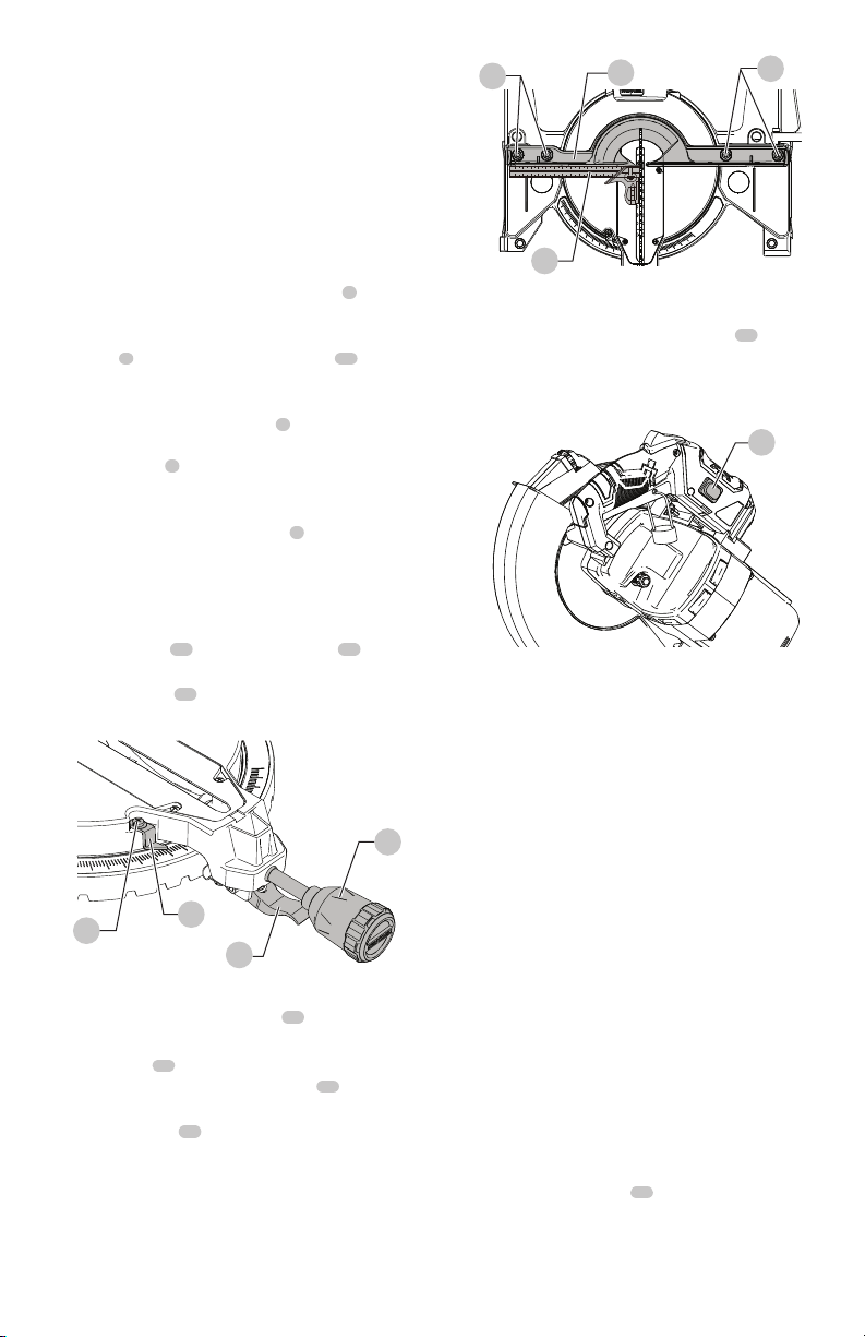
Adjusting Fence Squareness (Fig. V)
1. Loosen the four fence locking bolts
43
.
2. Lower the cutting arm and lock in position.
3. Using a square
34
, lay the heel of the square against
the blade and the ruler against the fence
11
as shown.
4. Adjust the fence 90° to the blade and tighten the four
fence locking bolts
43
.
NOTE: If the saw has not been used recently, recheck
blade squareness to the fence and readjust if needed.
5. After fence has been aligned, using a scrap piece of
wood, make a cut at 90° then check squareness on the
piece. Readjust if necessary.
Fig.U
7
8
41
42
Turning Laser Guide On (Fig. W)
1. To turn laser on, press on/off rocker switch
44
to “ON”
position.
2. To turn laser off, press on/off rocker switch to “OFF”
position.
Aligning The Laser Guide
The laser line must always be correctly aligned with the
blade to ensure straight, even cutting. The laser line will
enable you to preview the saw blade path on the stock
to be cut before starting the miter saw. This laser guide is
powered by the transformed alternating current supply
directly through the power lead. The saw must be
connected to the power source and the laser on/off
switch must be turned on for the laser line to show.
WARNING: To prevent serious injury, insert a padlock
(not provided) or chain with padlock through the hole
in the On/Off Trigger Switch prior to making any laser
adjustment.
WARNING: Do not remove the lock from the On/Off
Trigger Switch during any laser adjustment.
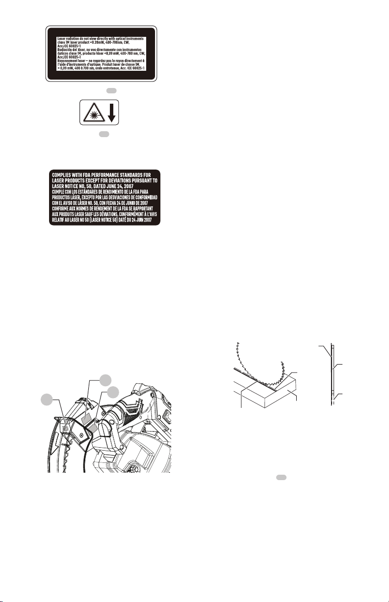
Avoid Direct Eye Contact With Laser
(Fig. X)
WARNING: A laser line radiates from the laser
aperture when the laser guide is turned on. Avoid
direct eye contact.
WARNING:
•
Laser Warning Label
45
: Laser radiation do
not view directly with optical instruments class 1M
laser product < 0.39 mW, 400-700 nm, CW, Acc.IEC
60825-1.
Fig.V
43
11
43
34
Fig.W
44
15
ENGLISH
•
Laser Aperture Label
46
•
Laser Notice Label
47
: COMPLIES WITH FDA
PERFORMANCE STANDARDS FOR LASER PRODUCTS
EXCEPT FOR DEVIATIONS PURSUANT TO LASER NOTICE
NO. 50, DATED JUNE 24, 2007
•
NOTE: All the adjustments for the operation of this
machine have been completed at the factory. Due to
normal wear and use, some occasional readjustments
may be necessary.
•
CAUTION: Use of controls or adjustments or
performance of procedures other than those specified
herein may result in hazardous radiation exposure.
•
CAUTION: The use of optical instruments with this
product will increase eye hazard.
•
WARNING: Do not attempt to repair or disassemble
the laser. If unqualified persons attempt to repair this
laser product, serious injury may result. Any repair
required on this laser product should be performed by
a qualified service dealer.
NOTE: If laser labels are missing, damaged or not clear,
contact with the Customer Care Center for replacement.
Fig.X
45
46
47
Laser Guide Adjustment (Fig. Y, Z, AA)
NOTE: All the adjustments for the operation of this machine
have been completed at the factory. Due to normal wear
and use, some occasional readjustments may be necessary.
WARNING: To prevent serious injury, insert a padlock
(not provided) or chain with padlock through the hole
in the ON/OFF Trigger Switch prior to making any
laser adjustment. DO NOT remove the lock from the
ON/OFF Trigger Switch during any laser adjustment.
A. Checking Laser Line Alignment (Fig. Y)
1. Set the saw to a 0° miter and 0° bevel setting.
2. Use a combination square to mark a 90° angle running
across the top and down the front of a board. This line
will serve as the pattern line to adjust the laser. Place the
board on the saw table.
3. Carefully lower the saw head down to align the saw
blade with the pattern line. Position the saw blade
to the left, center or right side of the “pattern line”
depending on your preference for the laser line location.
Lock board in place with hold-down clamp.
4. With the saw plugged in, turn on the laser guide. Your
saw has been preset with the laser line to the left side
of the blade.
WARNING: When making laser line adjustments,
keep fingers away from the ON/OFF trigger switch to
prevent accidental starting and possible serious injury.
5. Looking at the front of the board, if the laser line is
not parallel to the “pattern line” please follow the
instructions listed below under “Front Line” paragraph.
B. Adjusting the Position of the Laser Line
(Fig. Z, AA)
Front Line
If the laser line is angled from left to right, turn the laser
vertical adjustment knob
48
counterclockwise to align the
laser line parallel with pattern line. If the laser line is angled
from right to left, turn the knob clockwise to align the laser
line parallel with pattern line.
After performing the above adjustments, visually check that
both the front laser lines are parallel with pattern line.
Fig.Y
TOP VIEW
Laser line
Cutting
line
Blade
Laser line
Workpiece
Cutting
line
ENGLISH
16
OPERATION
WARNING: To reduce the risk of injury, turn unit
off and disconnect it from power source before
installing and removing accessories, before
adjusting or when making repairs. An accidental
start-up can cause injury.
WARNING: To ensure the blade path is clear of
obstructions, always make a dry run of the cut
without power before making any cuts on the
workpiece.
Before Using The Miter Saw
WARNING: To avoid mistakes that could cause
serious, permanent injury, do not plug the tool in
until the following steps are completed:
• Completely assemble and adjust the saw, following the
instructions. (ASSEMBLY & ADJUSTMENTS)
• Learn the use and function of the ON/OFF trigger
switch, on/off switch for laser, upper and lower blade
guards, head hold-down latch, bevel lock handle, and
cover plate screw.
• Review and understand all safety instructions and
operating procedures in this Operator’s Manual.
(SAFETY & OPERATION)
• Review the MAINTENANCE and TROUBLESHOOTING
GUIDE for your miter saw.
NOTE:
• Laser line is calibrated and set up at the factory to
project to the left of the blade.
• If you have any problem or questions concerning the
laser guide, call the Customer Care Center at 1-888-398-
7737.
Fig.Z
48
Fig.AA
Counterclockwise
(left)
Clockwise
(right)
• To avoid injury or possible death from electrical shock:
Make sure your fingers do not touch the plug’s metal
prongs when plugging or unplugging your miter saw.
(ELECTRICAL EQUIREMENTS AND SAFETY)
Before Each Use Inspect Your Saw
• Disconnect the miter saw. To avoid injury from
accidental starting, unplug the saw before any
adjustments, including set-up and blade changes.
• Compare the direction of rotation arrow on the
guard to the direction arrow on the blade. The blade
teeth should always point downward at the front of
the saw.
• Tighten the arbor bolt.
• Tighten the cover plate screw.
• Check for damaged parts.
Check for:
• Alignment of moving parts
• Damaged electric cords
• Binding of moving parts
• Broken/cracked castings: base, table, motor, upper
arm
• Function of arm return spring and lower guard:
Push the cutting arm all the way down, then let
it rise until it stops. The lower guard should fully
close. Follow instructions in TROUBLESHOOTING
GUIDE for adjustment if necessary.
• Other conditions that may affect the way the miter
saw works.
• Keep all guards in place, in working order and proper
adjustment. If any part of this miter saw is missing,
bent, damaged or broken in any way, or any electrical
parts don’t work, turn the saw off and unplug it.
• Replace bent, damaged, missing or defective parts
before using the saw again. All repairs should be done
by a certified and licensed technician.
• Maintain tools with care. Keep the miter saw clean for
best and safest performance. Follow instructions for
lubricating. Do not put lubricants on the blade while it
is spinning.
• Remove adjusting wrench from the tool before turning
it on.
• To avoid injury from jams, slips, or thrown pieces, use
only recommended accessories.
• Check the dust bag before you work. Empty the bag if it
is more than half-full.
Recommended Accessories
• Choose the correct 10 in. diameter blade for the
material and the type of cutting you plan to do.
• Make sure the blade is sharp, undamaged and properly
aligned. With the saw unplugged, push the cutting arm
all the way down. Manually spin the blade and check
for clearance. Tilt the power-head to a 45° bevel and
repeat the test.
Turn Knob
Pattern line

17
ENGLISH
• Make sure the blade and arbor collars are clean.
• Make sure all clamps and locks are tight and there is no
excessive play in any parts.
Keep Your Work Area Clean
Cluttered areas and benches invite accidents.
WARNING: To avoid burns or other fire damage,
never use the miter saw near flammable liquids,
vapors, or gases.
• Plan ahead to protect your eyes, hands, face and ears.
• Know your miter saw. Read and understand this
Instruction Manual and labels affixed to this tool. Learn
its application and limitations as well as the specific
potential hazards peculiar to this tool. To avoid injury
from accidental contact with moving parts, do not do
layout, assembly, or setup work on the miter saw while
any parts are moving.
• Avoid accidental starting, make sure the trigger switch
is disengaged before plugging the miter saw into a
power outlet.
Plan Your Work
• Use the right tool. Don’t force a tool or attachment to
do a job it was not designed to do. Use a different tool
for any workpiece that can’t be held in a solidly braced,
fixed position.
CAUTION: This machine is not designed for
cutting masonry, masonry products, ferrous
metals (steel, iron, and iron-based metals.)
Use this miter saw to cut only wood, wood-like
products, or non-ferrous metals. Other material
may shatter, bind the blade, or create other
dangers. Do not use this saw to cut tree limbs
or logs. Remove all nails that may be in the
workpiece to prevent sparking that could cause a
fire. Remove dust bag when cutting non-ferrous
metals.
Dress For Safety
Any power tool can throw foreign objects into the
eyes. This can result in permanent eye damage.
Everyday eyeglasses have only impact resistant
lenses and are not safety glasses. Glasses or goggles not
in compliance with ANSI Z87.1 could seriously injure you
when they break.
• Do not wear loose clothing, gloves, neckties or jewelry
(rings, watches). They can get caught and draw you
into moving parts.
• Wear non-slip footwear.
• Tie back long hair.
• Roll long sleeves above the elbow.
• Noise levels vary widely. To avoid possible hearing
damage, wear ear plugs when using any miter saw.
• Always wear a face mask or dust mask along with safety
goggles.
Inspect Your Workpiece
• Make sure there are no nails or foreign objects in the
part of the workpiece being cut.
• Plan your work to avoid small pieces that may bind or
are too small to clamp and hold securely.
• Plan the way you will grasp the workpiece from start to
finish. Avoid awkward operations and hand positions. A
sudden slip could cause your fingers or hand to move
into the blade.
Do Not Over-Reach
Keep good footing and balance. Keep your face and body
to one side, out of the line of a possible kickback. NEVER
stand in the line of the blade.
Never cut freehand:
• Brace your workpiece firmly against the fence and table
stop so it will not rock or twist during the cut.
• Make sure there is no debris between the workpiece
and the table or fence.
• Make sure there are no gaps between the workpiece,
fence and table that will let the workpiece shift after
it is cut.
• Keep the cut off piece free to move sideways after it
is cut off. Otherwise, it could get wedged against the
blade and thrown violently.
• Only the workpiece should be on the saw table.
• Secure work. Use clamps or a vice to help hold the
work.
Use Extra Caution With Large Or Odd
Shaped Workpieces
• Use extra supports (tables, sawhorses, blocks, etc.) for
workpieces large enough to tip.
• Never use another person as a substitute for a table
extension, or as an additional support for a workpiece
that is longer or wider than the basic miter saw table, or
to help feed, support, or pull the workpiece.
• Do not use this saw to cut small pieces. If the workpiece
being cut would cause your hand or fingers to be
within 7-5/16 in. of the saw blade the workpiece is too
small. Keep hands and fingers out of the “no-hands
zone” area marked on the saw table.
• When cutting odd shaped workpieces, plan your work
so it will not bind in the blade and cause possible
injury. Molding, for example, must lie flat or be held by
a fixture or jig that will not let it move when cut.
• Properly support round material such as dowel rods, or
tubing, which have a tendency to roll when cut.
ENGLISH
18
WARNING: To avoid injury, follow all applicable
safety instructions, when cutting non-ferrous metals:
• Use only saw blades specifically recommended for non-
ferrous metal cutting.
• Do not cut metal workpieces that must be hand held.
Clamp workpieces securely.
• Cut non-ferrous metals only if you are under the
supervision of an experienced person and the dust bag
has been removed from the saw.
When Saw Is Running
WARNING: Do not allow familiarity from frequent
use of your miter saw to result in a careless mistake.
A careless fraction of a second is enough to cause a
severe injury.
Before cutting, if the saw makes an unfamiliar noise
or vibrates, stop immediately. Turn the saw OFF.
Unplug the saw. Do not restart until finding and
correcting the problem.
Making A Basic Cut (Fig. BB)
WARNING: To ensure the blade path is clear of
obstructions, always make a dry run of the cut
without power before making any cuts on the
workpiece.
Body and Hand Position (Fig. CC)
Never place hands near the cutting area.
Proper positioning of your body and hands
when operating the miter saw will make
cutting easier and safer. Keep children away. Keep all
visitors at a safe distance from the miter saw. Make
sure bystanders are clear of the saw and workpiece.
Don’t force the saw.
Starting a cut:
• Place hands at least 7-5/16 in. away from the path of
the blade – out of the “no-hands zone”
49
shown in
Fig. CC on the next page.
• Always use the clamp to firmly hold the workpiece
against the fence and table to prevent movement
toward the blade.
• Turn the laser guide on for pre-alignment of your cut.
Fig.BB
• With the power switch OFF, bring the saw blade down
to the workpiece to see the cutting path of the blade.
Raise the saw blade back up before turning the saw on.
• Squeeze trigger switch to start saw.
• Lower blade into workpiece with a firm downward
motion.
Finishing a cut:
• Hold the cutting arm in the down position.
• Release trigger switch and wait for all moving parts to
stop before moving your hands and raising the cutting
arm.
• If the blade doesn’t stop within 10 seconds, unplug the
saw and follow the instructions in TROUBLESHOOTING
GUIDE section.
Before freeing jammed material:
• Release trigger switch.
• Wait for all moving parts to stop.
• Unplug the miter saw
Basic Saw Operations
WARNING: For your convenience, your saw has
a blade brake. The brake is not a safety device.
Never rely on it to replace the proper use of the
guard on your saw. If the blade doesn’t stop
within approximately 10 seconds, wait for the
blade to stop, unplug the saw and contact the
qualified service dealer.
Turning The Saw On (Fig. DD)
This miter saw is equipped with an ON/OFF trigger
switch
50
. With the safety lock
1
pressed, squeeze the
trigger switch to turn the miter saw ON.
NOTE:
• To make the ON/OFF switch childproof. Insert a padlock
(not provided), or chain with padlock, through the
hole
51
in the trigger switch. Locking the tool’s switch,
preventing children and other unqualified users from
turning the machine on.
Fig.CC
49
7-5/16 in. 7-5/16 in.
19
ENGLISH
• The miter saw is equipped with an electric blade brake.
When the trigger switch is released, the blade brake
will stop the blade within approximately 10 seconds.
Before Leaving The Saw
• Never leave tool running unattended. Turn power OFF.
Wait for all moving parts to stop.
• Make workshop childproof. Lock the shop. Disconnect
master switches. Store tool away from children and
other unqualified users.
WARNING: To avoid injury from materials
being thrown, always unplug the saw to avoid
accidental starting, and remove small pieces of
material from the table cavity. The table insert
may be removed for this purpose, but always
reattach the table insert prior to performing a
cutting operation.
Miter Cut (Fig. EE)
1. When a miter cut is required, unlock the miter table by
turning the miter handle
7
counterclockwise.
2. While holding the miter handle, lift up on the positive
stop locking lever
8
.
3. Rotate the miter table to the right or left with the miter
handle.
4. When the table is in the desired position, as shown on
the miter scale
52
, release the positive stop locking
lever and tighten the miter handle. The table is now
locked at the desired angle. Positive stops are provided
at 0°, 15°, 22.5°, 31.6°, 45° right & left, and 55° right.
IMPORTANT: Always tighten the miter handle
7
before performing every cutting operation.
5. Turn the laser guide on and position the workpiece on
the table for pre-alignment of your cut.
Fig.DD
1
50
51
Bevel Cut (Fig. FF)
WARNING: NEVER BEVEL to the right, this saw
is designed to only be used for cutting left bevel
cuts.
1. When a bevel cut is required, loosen the bevel lock
knob
12
by turning it clockwise.
2. Tilt the cutting head to the desired angle, as shown on
the bevel scale
53
.
3. The blade can be positioned at any angle, from a 90°
straight cut (0° on the scale) to a 47° left bevel. Tighten
the bevel lock knob
12
to lock the cutting head in
position.
4. Turn the laser guide on and position the workpiece on
the table for pre-alignment of your cut.
Compound Cut (Fig. GG)
WARNING: NEVER BEVEL to the right, this saw
is designed to only be used for cutting left bevel
cuts.
A compound cut is the combination of a miter and a bevel
cut simultaneously.
1. Loosen the miter handle
7
. Lift up the positive stop
locking lever
8
and position the table at the desired
angle. Release the positive stop locking lever
8
and lock
the miter handle
7
.
2. Loosen the bevel lock knob
12
and position the cutting
head at the desired bevel position. Lock the bevel lock
knob
12
.
3. Turn the laser guide on and position the workpiece on
the table for pre-alignment of your cut.
Fig.EE
7
8
52
Fig.FF
12
53

ENGLISH
20
WARNING: As the right miter angle is greater
than 48°, do not combine with any bevel angle to
prevent interference with the fence.
Cutting Bowed Material (Fig. HH)
WARNING: To avoid injury from materials being
thrown, always unplug the saw to avoid accidental
starting and remove small pieces of material from the
table cavity underlying the table insert.
The table insert may be removed for this purpose,
but always reattach table insert prior to performing a
cutting operation.
A bowed workpiece
54
must be positioned against the
fence and secured with a hold-down clamp
4
as shown
before cutting. Do not position workpiece incorrectly or try
to cut the workpiece without the support of the fence. This
will cause the blade to bind and could result in personal
injury.
Fig.GG
7
8
12
Fig.HH
4
54
Workpiece Support (Fig. II)
Long pieces need extra support. The support should be
placed under the workpiece. Keep your hand holding the
workpiece positioned 7-5/16 inches or more away from the
blade. The support must let the workpiece lay flat on the
work table during the cutting operation.
NOTE: When mounted on a flat surface, the saw table is
3-1/2 inches high.
Support Base As Extension Table (Fig. JJ)
WARNING: Before using, make sure the height of the
saw table matches the height of the support base.
1. Place the miter saw and support base
10
on a flat,
stable surface with the support base on the side of the
miter saw where the support is needed.
2. Adjust the position of the support base according to
the length of the workpiece to provide extra support.
Auxiliary Wood Fence (Fig. KK)
When making multiple or repetitive cuts that result in
cut-off pieces of one inch or less, it is possible for the saw
blade to catch the cut-off piece and throw it out of the
saw or into the blade guard and housing, possibly causing
damage or injury. To minimize this, an auxiliary wood fence
can be mounted to your saw.
Holes are provided in the saw fence to attach an auxiliary
wood fence. This fence is to be constructed of straight
wood approximately 3/4 in. thick by 2-1/2 in. high by
22 in. long.
Fig.II
3-1/2 in.
Fig.JJ
10
21
ENGLISH
Attach the wood fence securely and make a full depth cut
to make a blade slot.
Check for interference between the wood fence and the
lower blade guard. Adjust if necessary.
NOTE: This auxiliary fence is used only with the saw blade
in the 0° bevel position (90° to the table). The auxiliary
wood fence must be removed when bevel cutting.
Cutting Base Molding (Fig. LL)
Base moldings and many other moldings can be cut on a
compound miter saw. The setup of the saw depends on
molding characteristics and application, as shown. Perform
practice cuts on scrap material to achieve best results:
1. Always make sure moldings rest firmly against fence
and table. Use hold-down, crown molding vice or
C-clamps, whenever possible, and place tape on the
area being clamped to avoid marks.
2. Reduce splintering by taping the cut area prior to
making the cut. Mark the cut line directly on the tape.
3. Splintering typically happens due to an incorrect blade
application and thinness of the material.
Fig.KK
Blade slot
Fig.LL
F
e
n
c
e
Miter saw table
Miter at 45°, bevel at 0° Miter at 0°, bevel at 45°
F
e
n
c
e
Miter saw table
Workpiece
Workpiece
Cutting Crown Molding (Fig. MM, NN)
Your compound miter saw is suited for the difficult task
of cutting crown molding. To fit properly, crown molding
must be compound-mitered with extreme accuracy.
The two surfaces on a piece of crown molding that fit
flat against the ceiling and wall are at angles that, when
added together, equal exactly 90°.
Most crown molding has a top rear angle (the section that
fits flat against the ceiling) of 52° and a bottom rear angle
(the section that fits flat against the wall) of 38°.
In order to accurately cut crown molding for a 90° inside or
outside corner, lay the molding with its broad back surface
flat on the saw table.
When setting the bevel and miter angles for compound
miters, remember that the settings are interdependent.
Fig.MM
Fig.NN
F
e
n
c
e
Miter saw table
Workpiece
Compound cut crown moldings
Inside corner
Outside corner
OR
OL
IR
IL
Settings for standard crown molding lying flat on
compound miter saw table

ENGLISH
22
Bevel/Miter Settings
NOTE: The chart below references a compound cut for crown molding ONLY WHEN THE ANGLE BETWEEN THE
WALLS EQUALS EXACTLY 90°.
KEY
BEVEL ANGLE
SETTING
MITER ANGLE
SETTING
TYPE OF CUT
Inside Corner - Left Side
IL 33.9° 31.6° Right
1. Position top of molding against fence.
2. LEFT side is finished piece.
Inside Corner - Right Side
IR 33.9° 31.6° Left
1. Position bottom of molding against fence.
2. LEFT side is finished piece.
Outside Corner-Left Side
OL 33.9° 31.6° Left
1. Position bottom of molding against fence.
2. RIGHT side is finished piece.
Outside Corner - Right Side
OR 33.9° 31.6° Right
1. Position top of molding against fence.
2. RIGHT side is finished piece.

23
ENGLISH
CROWN MOLDING CHART
Compound Miter Saw
Miter and Bevel Angle Settings
Wall to Crown Molding Angle
52/38° Crown Molding 45/45° Crown Molding
Angle
Between
Walls
Miter
Setting
Bevel
Setting
Miter
Setting
Bevel
Setting
67 42.93 41.08 46.89 36.13
68 42.39 40.79 46.35 35.89
69 41.85 40.50 45.81 35.64
70 41.32 40.20 45.28 35.40
71 40.79 39.90 44.75 35.15
72 40.28 39.61 44.22 34.89
73 39.76 39.30 43.70 34.64
74 39.25 39.00 43.18 35.38
75 38.74 38.69 42.66 34.12
76 38.24 38.39 42.15 33.86
77 37.74 38.08 41.64 33.60
78 37.24 37.76 41.13 33.33
79 36.75 37.45 40.62 33.07
80 36.27 37.13 40.12 32.80
81 35.79 36.81 39.62 32.53
82 35.31 36.49 39.13 32.25
83 34.83 36.17 38.63 31.98
84 34.36 35.85 38.14 31.70
85 33.90 35.52 37.66 31.42
86 33.43 35.19 37.17 31.34
87 32.97 34.86 36.69 30.86
88 32.52 34.53 36.21 30.57
89 32.07 34.20 35.74 30.29
90 31.62 33.86 35.26 30.00
91 31.17 33.53 34.79 29.71
92 30.73 33.19 34.33 29.42
93 30.30 32.86 33.86 29.13
94 29.86 32.51 33.40 28.83
95 29.43 32.17 32.94 28.54
96 29.00 31.82 32.48 28.24
97 28.58 31.48 32.02 27.94
98 28.16 31.13 31.58 27.64
99 27.74 30.78 31.13 27.34
100 27.32 30.43 30.68 27.03
101 26.91 30.08 30.24 26.73
102 26.50 29.73 29.80 26.42
103 26.09 29.38 29.36 26.12
104 25.69 29.02 28.92 25.81
105 25.29 28.67 28.48 25.50
106 24.89 28.31 28.05 25.19
107 24.49 27.96 27.62 24.87
108 24.10 27.59 27.19 24.56
109 23.71 27.23 26.77 24.24
110 23.32 26.87 26.34 23.93
111 22.93 26.51 25.92 23.61
112 22.55 26.15 25.50 23.29
113 22.17 25.78 25.08 22.97
114 21.79 25.42 24.66 22.66
115 21.42 25.05 24.25 22.33
116 21.04 24.68 23.84 22.01
117 20.67 24.31 23.43 21.68
118 20.30 23.94 23.02 21.36
119 19.93 23.57 22.61 21.03
120 19.57 23.20 22.21 20.70
121 19.20 22.83 21.80 20.38
122 18.84 22.46 21.40 20.05
123 18.48 22.09 21.00 19.72
52/38° Crown Molding 45/45° Crown Molding
Angle
Between
Walls
Miter
Setting
Bevel
Setting
Miter
Setting
Bevel
Setting
124 18.13 21.71 20.61 19.39
125 17.77 21.34 20.21 19.06
126 17.42 20.96 19.81 18.72
127 17.06 20.59 19.42 18.39
128 16.71 20.21 19.03 18.06
129 16.37 19.83 18.64 17.72
130 16.02 19.45 18.25 17.39
131 15.67 19.07 17.86 17.05
132 15.33 18.69 17.48 16.71
133 14.99 18.31 17.09 16.38
134 14.66 17.93 16.71 16.04
135 14.30 17.55 16.32 15.70
136 13.97 17.17 15.94 15.36
137 13.63 16.79 15.56 15.02
138 13.30 16.40 15.19 14.62
139 12.96 16.02 14.81 14.34
140 12.63 15.64 14.43 14.00
141 12.30 15.25 14.06 13.65
142 11.97 14.87 13.68 13.31
143 11.64 14.48 13.31 12.97
144 11.31 14.09 12.94 12.62
145 10.99 13.71 12.57 12.29
146 10.66 13.32 12.20 11.93
147 10.34 12.93 11.83 11.59
148 10.01 12.54 11.46 11.24
149 9.69 12.16 11.09 10.89
150 9.37 11.77 10.73 10.55
151 9.05 11.38 10.36 10.20
152 8.73 10.99 10.00 9.85
153 8.41 10.60 9.63 9.50
154 8.09 10.21 9.27 9.15
155 7.77 9.82 8.91 8.80
156 7.46 9.43 8.55 8.45
157 7.14 9.04 8.19 8.10
158 6.82 8.65 7.83 7.75
159 6.51 8.26 7.47 7.40
160 6.20 7.86 7.11 7.05
161 5.88 7.47 6.75 6.70
162 5.57 7.08 6.39 6.35
163 5.26 6.69 6.03 6.00
164 4.95 6.30 5.68 5.65
165 4.63 5.90 5.32 5.30
166 4.32 5.51 4.96 4.94
167 4.01 5.12 4.61 4.59
168 3.70 4.72 4.25 4.24
169 3.39 4.33 3.90 3.89
170 3.08 3.94 3.54 3.53
171 2.77 3.54 3.19 3.10
172 2.47 3.15 2.83 2.83
173 2.15 2.75 2.48 2.47
174 1.85 2.36 2.12 2.12
175 1.54 1.97 1.77 1.77
176 1.23 1.58 1.41 1.41
177 0.92 1.18 1.06 1.06
178 0.62 0.79 0.71 0.71
179 0.31 0.39 0.35 0.35

ENGLISH
24
MAINTENANCE
WARNING: To reduce the risk of injury, turn unit
off and disconnect it from power source before
installing and removing accessories, before
adjusting or when making repairs. An accidental
start-up can causeinjury.
DANGER: To avoid injury, never put lubricants on
the blade while it is spinning.
WARNING: To avoid fire or toxic reaction, never
use gasoline, naphtha acetone, lacquer thinner
or similar highly volatile solvents to clean the
miter saw.
WARNING: To avoid injury from unexpected
starting or electrical shock, unplug the power
cord before working on the saw.
WARNING: To avoid electrical shock, fire or
injury, use only parts identical to those identified
in the parts list. Reassemble exactly as the original
assembly to avoid electrical shock.
Replacing Carbon Brushes (Fig. OO)
The carbon brushes furnished will last approximately
50 hours of running time, or 10,000 ON/OFF cycles. Replace
both carbon brushes when either has less than 1/4 in.
length of carbon remaining, or if the spring or wire is
damaged or burned. To inspect or replace brushes, first
unplug the saw. Then remove the black plastic cap
55
on the side of the motor
56
. Remove the cap cautiously,
because it is springloaded. Then pull out the carbon
brush
57
and replace. To reassemble, reverse the
procedure. The ears on the metal end of the assembly go
in the same hole the carbon part fits into. Tighten the cap
snugly, but do not overtighten. Repeat for the carbon brush
located on the other side of motor.
NOTE: To reinstall the same brushes, first make sure the
brushes go back in the way they came out. This will avoid
a break-in period that reduces motor performance and
increases wear.
Fig.OO
55
56
57
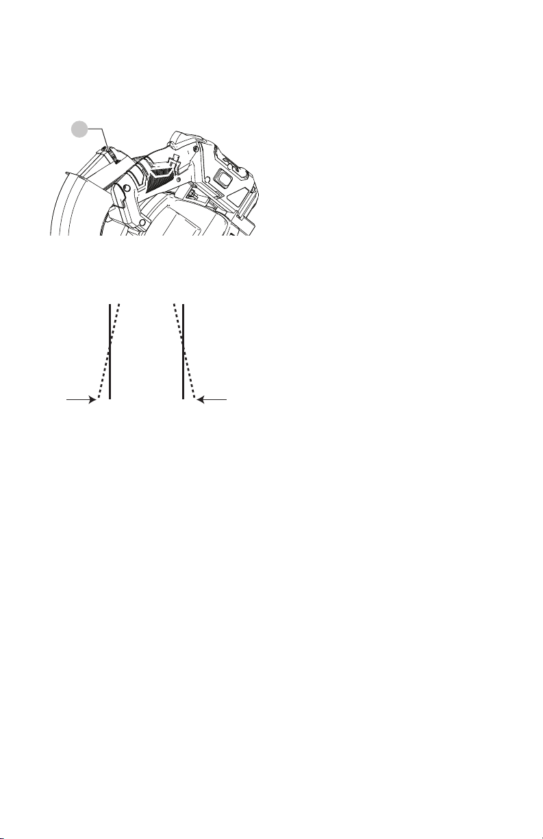
Lower Blade Guard
Do not use the saw without the lower blade guard.
The lower blade guard is attached to the saw for your
protection. Should the lower guard become damaged,
do not use the saw until the damaged guard has been
replaced. Regularly check to make sure the lower guard
is working properly. Also check before each use that all
bolts/screws are tight. Clean the lower guard of any dust or
buildup with a damp cloth.
WARNING: When cleaning the lower guard, unplug
the saw from the power source receptacle to avoid
unexpected start-up.
WARNING: Do not use solvents on the guard. They
could make the plastic “cloudy” and brittle.
Sawdust
Periodically, sawdust will accumulate under the work table
and base. This could cause difficulty in the movement of
the worktable when setting up a miter cut. Frequently
blow out or vacuum up the sawdust.
Remove small pieces of material from the table cavity if
needed. (See the section on Removing and Installing the
Table Insert on page 12.)
To empty the dust bag, remove the sawdust bag from the
dust collection elbow. Open the zipper on the sawdust bag
and empty out the sawdust inside. Close the zipper and
reinstall the dust bag as described on page 9.
WARNING: Wear proper eye protection to keep
debris from entering eyes when removing
sawdust from unit.
Lubrication (Fig. PP)
All the motor bearings in this tool are lubricated with a
sufficient amount of high grade lubricant for the life of
the unit under normal operating conditions; therefore, no
further lubrication is required.
Lubricate the following as necessary:
Chop pivot: Apply light machine oil to points indicated in
illustration.
Central pivot of plastic guard: Use light household
oil (sewing machine oil) on metal-to-metal or metal-to-
plastic guard contact areas as required for smooth, quiet
operation. Avoid excessive oil, to which sawdust will cling.
Fig.PP
Central pivot of
plastic guard
(oil here)
Chop Pivot (oil here
and on opposite side)
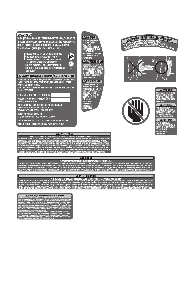
25
ENGLISH
Free Warning Label Replacement
If your warning labels become illegible or are missing, call 1-888-398-7737 for a free replacement.

ENGLISH
26
TROUBLESHOOTING GUIDE
BE SURE TO FOLLOW SAFETY RULES AND INSTRUCTIONS
For assistance with your product, visit our website at www.craftsman.com for a list of service centers, or call CRAFTSMAN
at 1-888-398-7737.
MOTOR
PROBLEM CAUSE CORRECTION
Brake does not stop the
blade within 10 seconds.
1. Motor brushes not sealed or lightly sticking.
2. Motor brake overheated from use of defective or
wrong size blade or rapid ON/OFF cycling.
3. Arbor bolt loose.
4. Brushes cracked, damaged, etc.
5. Other.
1. Inspect/clean/replace brushes. See MAINTENANCE section.
2. Use a recommended blade. Let cool down. See REMOVING OR
INSTALLING THE BLADE section.
3. Retighten. See REMOVING OR INSTALLING THE BLADE section.
4. Replace brushes.
5. Contact Service Center or Authorized Service Station.
Motor does not start. 1. Limit switch failure
2. Brush worn.
3. Fuse blown or circuit breaker tripped on home panel.
1. Replace limit switch.
2. Replace brushes. See MAINTENANCE section.
3. Verify there is electrical power at the outlet.
Brush spark when switch
released.
1. Brush worn.
2. Other.
1. Replace Brushes. See MAINTENANCE section.
2. Contact Service Center or Authorized Service Station.
SAW OPERATION
PROBLEM CAUSE CORRECTION
Blade hits table. 1. Misalignment. 1. Contact Service Center or Authorized Service Station.
Angle of cut not accurate.
Can not adjust miter.
1. Miter table unlocked.
2. Sawdust under table.
1. See OPERATION - Miter Angle Adjustment section.
2. Vacuum or blow out dust. WEAR EYE PROTECTION.
Cutting arm wobbles. 1. Loose pivot points. 1. Contact Service Center or Authorized Service Station.
Cutting arm will not fully
raise, or blade guard
won’t fully close.
1. Pivot spring not replaced properly after service.
2. Sawdust build-up.
1. Contact Service Center or Authorized Service Station.
2. Clean and lubricate moving parts.
Blade binds, jams, burns
wood.
1. Improper operation.
2. Dull or warped blade.
3. Improper blade size.
4. Wood is moving during cut.
1. See BASIC SAW OPERATION section.
2. Replace or sharpen blade.
3. Replace with 10 in. (254 mm) diameter blade.
4. Use hold-down clamp to secure workpiece to table.
Saw vibrates or shakes. 1. Saw blade not round / damaged / loose.
2. Arbor bolt loose.
1. Replace blade.
2. Tighten arbor bolt.

27
ENGLISH
Register Online
Thank you for your purchase. Register your product now for:
• WARRANTY SERVICE: Registering your product will
help you obtain more efficient warranty service in case
there is a problem with your product.
• CONFIRMATIONOF OWNERSHIP: In case of an
insurance loss, such as fire, flood or theft, your
registration of ownership will serve as your proof of
purchase.
• FOR YOUR SAFETY: Registering your product will
allow us to contact you in the unlikely event a safety
notification is required under the Federal Consumer
Safety Act.
Register online at www.craftsman.com/registration
Three Year Limited Warranty
CRAFTSMAN will repair or replace, without charge, any
defects due to faulty materials or workmanship for one year
from the date of purchase. This warranty does not cover
part failure due to normal wear or tool abuse. For further
detail of warranty coverage and warranty repair information,
visit www.craftsman.com or call 1-888-398-7737. This
warranty does not apply to accessories or damage caused
where repairs have been made or attempted by others.
THIS LIMITED WARRANTY IS GIVEN IN LIEU OF ALL OTHERS,
INCLUDING THE IMPLIED WARRANTY OF MERCHANTABILITY
AND FITNESS FOR A PARTICULAR PURPOSE, AND EXCLUDES
ALL INCIDENTAL OR CONSEQUENTIAL DAMAGES. Some
states do not allow limitations on how long an implied
warranty lasts or the exclusion or limitation of incidental
or consequential damages, so these limitations may not
apply to you. This warranty gives you specific legal rights
and you may have other rights which vary in certain states
or provinces.
90 DAY MONEY BACK GUARANTEE
If you are not completely satisfied with the performance of
your CRAFTSMAN Power Tool, Laser, or Nailer for any reason,
you can return it within 90 days from the date of purchase
with a receipt for a full refund – no questions asked.
LATINAMERICA: This warranty does not apply to products
sold in Latin America. For products sold in Latin America,
see country specific warranty information contained either
in the packaging, call the local company or see website for
warranty information.

ENGLISH
28
PARTS LIST
10 in. (254 mm) Folding Compound Miter Saw
Parts list for folding compound miter saw - A
I.D. No. Description Size Q'ty I.D. No. Description Size Q'ty
X7WJ POWER CABLE ASS’Y 1 X7XW
CR. RE. TRUSS HD. ROUND NECK SCREW
M6*14 1
X7WK ROCKER SWITCH ASS’Y 1 X7XX
CR. RE. TRUSS HD. ROUND NECK SCREW
M6*14 1
X7WL LASER ASS'Y 1 X7XY CR. RE. TRUSS HD. SCREW M5*12 2
X7WM HOLD-DOWM CLAMP ASS'Y 1 X7XZ CR. RE. COUNT HD. SCREW M6*20 1
X7WN BLADE 1 X7Y0 ARBOR BOLT M8*18 1
X7WP LIMIT SWITCH 1 X7Y1 HEX. SOC. SET SCREW M5*12 1
X7WQ LEAD WIRE ASS'Y 1 X7Y2 HEX. SOC. SET SCREW M6*10 1
X7WR LEAD WIRE ASS'Y 1 X7Y3 HEX. SOC. SET SCREW M6*10 2
X7WS TERMINAL 2 X7Y4 HEX. SOC. HD. CAP BOLT M6*16 1
X7WT CR. RE. PAN HD. SCREW M5*16 1 X7Y5 HEX. SOC. HD. CAP BOLT M6*12 1
X7WU CR. RE. PAN HD. SCREW M5*8 1 X7Y6 WAVE WASHER φ8 1
X7WV CR. RE. PAN HD. TAPPING SCREW M4*16 2 X7Y7 FLAT WASHER
φ6*φ13*1
1
X7WW CR. RE. PAN HD. TAPPING SCREW M4*16 6 X7Y8 FLAT WASHER
φ8*φ15*1
1
X7WX CR. RE. PAN HD. TAPPING SCREW M3*8 1 X7Y9 ANCHOR BLOCK 1
X7WY CR. RE. TRUSS HD. SCREW M5*20 2 X7YA COLLAR 1
X7WZ COMPRESSION SPRING 1 X7YB ANCHOR BLOCK 1
X7X0 CORD CLAMP 1 X7YC LOWER BLADE GUARD 1
X7X1 BUTTON SWITCH 1 X7YD SPECIAL BOLT 1
X7X2 TRIGGER 1 X7YE CUTTER SHAFT GUARD 1
X7X3 FOLLOWER PLATE 1 X7YF CABLE SHIELD 1
X7X4 MOTOR HANDLE (RIGHT) 1 X7YG LEVER 1
X7X5 MOTOR HANDLE (LEFT) 1 X7YH SPRING GUARD 1
X7XB CR. RE. COUNT HD. SCREW M4*8 4 X7YJ BRACING PLATE 1
X7XE LASER COVER (RIGHT) 1 X7YK ARBOR COLLAR 2
X7XF LASER COVER (LEFT) 1 X7YN POWER CABLE 1
X7XM CONTROLLER ASS'Y 1 X7YP MAGIC TAPE 1
X7XN COMPRESSION SPRING 1 X7YZ INSTRUCTION MANUAL 1
X7XR CORD GUARD 1 X7Z3 TRADEMARK LABEL 1
X7XT LOCK NUT M6 1 X7Z4 WARNING LABEL 1
X7XU NUT M6 2 X7Z5 LASER STICKER 1
X7XV CR. RE. PAN HD. ROUND NECK SCREW M6*9 1 X7Z6 WARNING LABEL 2

29
ENGLISH
10 in. (254 mm) Folding Compound Miter Saw
Parts list for folding compound miter saw - B
I.D. No. Description Size Q'ty I.D. No. Description Size Q'ty
X7Z7 WARNING LABEL 1 X805 TORSION SPRING 1
X7Z8 CAUTION LABEL 1 X806 SHAFT SLEEVE 1
X7Z9 WARNING LABEL 1 X807 CLAMP BOLT 2
X7ZA WARNING LABEL 1 X808 ANGLE PEGULATOR 1
X7ZB WARNING LABEL 1 X809 BEVEL LOCK KNOB 1
X7ZC WARNING LABEL 1 X80A NEEDLE POINTER 1
X7ZD CAUTION LABEL 1 X80B TABLE 1
X7ZE WARNING LABEL 1 X80C NEEDLE POINTER 1
X7ZF WARNING LABEL 1 X80D MITER HANDLE 1
X7ZG LABEL 1 X80E TABLE INSERT 1
X7ZH SCALE 1 X80F LOCATION PIN 1
X7ZJ TILTING SCALE 1 X80G INNER HEX. BOLT M6*16 2
X7ZK LASER WARNING LABEL 1 X80H ANCHOR PLATE 1
X7ZL LOCK NUT 1 X80J PLUNGER HANDLE 1
X7ZM NUT 1 X80K TENSION PLATE 1
X7ZN LOCK NUT 1 X80L SHAFT 1
X7ZP HEX. NUT 1 X80M PIVOT SHAFT 1
X7ZQ CR. RE. PAN HD. SCREW M5*8 1 X80N COMPRESSION SPRING 1
X7ZR CR. RE. PAN HD. SCREW M5*8 2 X80P CLEVIS PIN 1
X7ZS CR. RE. PAN HD. SCREW M5*8 1 X80Q HEX. SOC. HD. CAP SCREW M8*30 4
X7ZT CR. RE. PAN HD. SCREW M4*10 4 X80R HEX. SOC. HD. CAP SCREW M6*30 2
X7ZV HEX. SOC. SET SCREW M6*8 1 X80S BLADE WRENCH 1
X7ZW HEX. SOC. HD. CAP BOLT M5*35 1 X80T CENTER BOLT 1
X7ZX HEX. HD. BOLT M6*20 1 X80U SUPPORT BASE 1
X7ZY O-RING 1 X80V CARRYING HANDLE 1
X7ZZ C-RING 1 X80W SLIDE PLATE 1
X800 DISC SPRING WASHER φ12 1 X80X BASE 1
X801 FLAT WASHER 5/16*7/8-5/64 1 X80Y FENCE 1
X802 FLAT WASHER φ8*φ16*2.5 1 X832 ARM 1
X803 FLAT WASHER φ12*φ25*1.5 1 X837 DUST BAG ASS'Y 1
X804 COMPRESSION SPRING 1
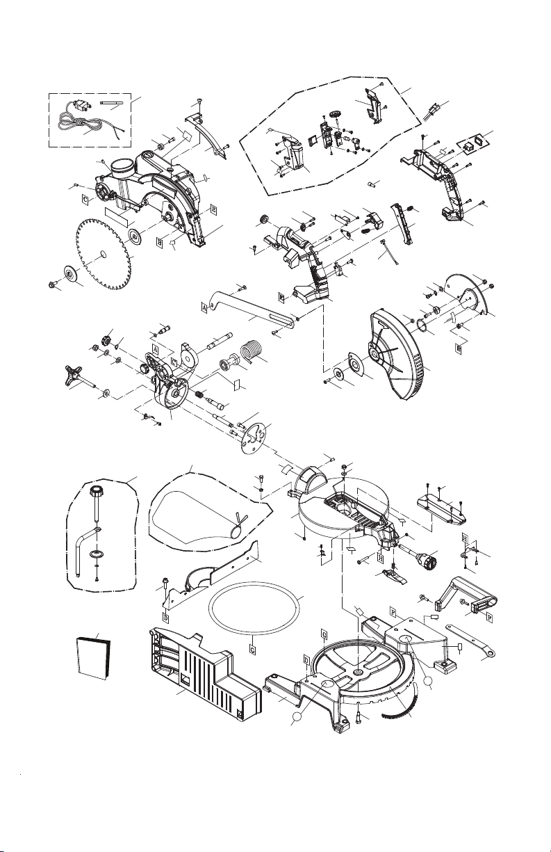
ENGLISH
30
10 in. (254 mm) Folding Compound Miter Saw
Schematic for folding compound miter saw
X7WJ
X7YP
X7YN
X7Y3
2
X7Y2
X7Y9
X7Y5
X7ZG
X7XY
2
X7YF
X7ZA
X832
X7Z5
X7Z3
X7WN
X7YK
2
X7Y0
X7Z4
X7XB
4
X7ZK
X7XF
X7XE
X7WL
X7WR
X7WK
X7Z9
X7WT
X7WW
6
X7X4
X7WZ
X7X2
X7WS
2
X7X1
X7WX
X7XM
X7WV
2
X7X0
X7XR
X7WU
X7XX
X7XW
X7Y7
X7YG
X80L
X7X5
X7WP
X7WY
2
X7WQ
X7X3
X7XN
X80F
X7ZY
X807
X807
X7ZZ
X7ZM
X800
X803
X809
X801
X80C
X7ZS
X808
X804
X80P
X80M
X80G
2
X80H
X7Z7
X806
X805
X7XZ
X7YA
X7YJ
X7YC
X7YH
X7YD
X7YE
X7ZC
X7XT
X7Y4
X7YB
X7XV
X7Y6
X7Y8
X7XU
2
X7Y1
X7ZL
X802
X7ZJ
X7ZX
X7ZP
X837
X7WM
X7YZ
X80Q
4
X80Y
X80B
X7ZV
X7ZQ
X80A
X80W
X7Z8
X7ZF
X7ZW
X80J
X80N
X80D
X7ZN
X7ZE
X7ZR
2
X80K
X80E
X7ZT
4
X80V
X80R
2
X7ZB
X7ZD
X80S
X7Z6
X7Z6
X7ZH
X80T
X80X
X80U
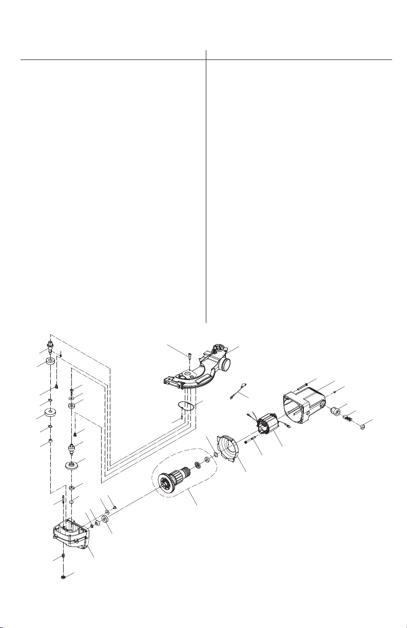
31
ENGLISH
10 in. (254 mm) Folding Compound Miter Saw
Parts list & schematic for motor
X831
X834
X81S
X82X
X82D
X835
X82S
2
X82G
2
X830
X82M
X82Z
X836
X81U
X82E
2
X82E
3
X82W
X82Q
X82B
X82P
X82U
X81V
X82N
X82L
X82T
X82Y
X82A
X82R
X81T
X82F
2
X81R
X82C
X815
2
X816
2
X817
2
X82K
2
X818
X82H
4
X833
X82V
2
X832
X82J
4
I.D. No. Description Size Q'ty I.D. No. Description Size Q'ty
X815 BRUSH COVER 2 X82M O-RING ROD 1
X816 BRUSH ASS'Y 2 X82N PARALLEL KEY 1
X817 BRUSH HOLDER ASS'Y 2 X82P C-RING 1
X818 MOTOR COVER 1 X82Q C-RING 1
X81R FIELD ASS'Y 1 X82R WAVE WASHER φ22 1
X81S GEAR BOX 1 X82S FLAT WASHER 1/4*3/4-1/16 2
X81T FLOW GUIDE 1 X82T FLAT WASHER φ5*φ16*2 1
X81U GEAR SHAFT 1 X82U BALL BEARING 1
X81V CUTTER SHAFT 1 X82V NEEDLE ROLLER 2
X82A ARMATURE ASS'Y 1 X82W NEEDLE ROLLER BEARING 1
X82B HELIX GEAR 1 X82X BALL BEARING 1
X82C LEAD WIRE ASS'Y 1 X82Y BALL BEARING 1
X82D HEX. NUT M8 1 X82Z BALL BEARING 1
X82E CR. RE. PAN HD. SCREW M5*6 5 X830 CLEVIS PIN 1
X82F
CR. RE. PAN HD.TAPPING SCREW & WASHER
ST4.8*50 2 X831 LOCK KNOB 1
X82G CR. RE. PAN HD. TAPPING SCREW M5*8 2 X832 ARM 1
X82H CR. RE. PAN HD. SCREW & WASHER M5*50 4 X833 OIL PAPER 1
X82J HEX. SOC. HD. CAP SCREW M5*25 4 X834 COMPRESSION SPRING 1
X82K HEX. SOC. SET SCREW M5*6 2 X835 STRAIGHT BEVEL GEAR 1
X82L HEX. SOC. HD. CAP BOLT M5*10 1 X836 STRAIGHT BEVEL GEAR 1

ENGLISH
32
NOTES