Loading ...
Loading ...
Loading ...
INTRODUCTION
11
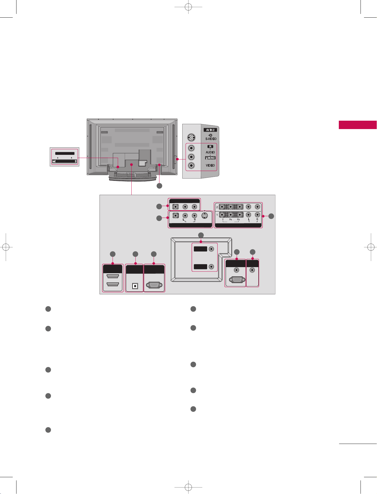
CONNECTION OPTIONS
Back Connection Panel
HDMI IN
DIGITAL AUDIO
OUT
OPTICAL
2
1 (DVI)
RS-232C IN
(CONTROL & SERVICE)
RGB (PC/DTV)
RGB IN
AUDIO (RGB/DVI)
COMPONENT IN
VIDEO
AUDIO
VIDEO
AUDIO
( )
S-VIDEO
AV IN 1
AV OUT
ANTENNA
IN
CABLE
IN
REMOTE
CONTROL IN
Cable CARD
HDMI INHDMI IN
DIGITAL AUDIO DIGITAL AUDIO
OUTOUT
OPTICALPTICAL
2
1 (DVI)
1 (DVI)
RS-232C INRS-232C IN
(CONTROL & SERVICE)(CONTROL & SERVICE)
RGB (PC/DTV)RGB (PC/DTV)
RGB INRGB IN
AUDIO (RGB/DVI)AUDIO (RGB/DVI)
COMPONENT INCOMPONENT IN
VIDEOVIDEO
AUDIOAUDIO
VIDEOVIDEO
AUDIOAUDIO
MONO
( )
S-VIDEOS-VIDEO
AV IN 1AV IN 1
AV OUTAV OUT
ANTENNAANTENNA
ININ
CABLECABLE
ININ
REMOTEREMOTE
CONTROL INCONTROL IN
S-VIDEO Input
Provides better picture quality than the
video input.
AUDIO Input
Connections are available for listening to
stereo sound from an external device.
VIDEO Input
Connects the video signal from a video
device.
CableCARD
™
Used for
CableCARD
™
Cable Service
Provider.
AV OUT
Connect a second TV or monitor.
AV (Audio/Video) IN 1
Connect audio/video output from an external
device to these jacks.
S-VIDEO
Connect S-Video out from an S-VIDEO device.
COMPONENT IN
Connect a component video/audio device to these
jacks.
HDMI IN
Connect a HDMI signal to 1(DVI) or 2.
Or DVI(VIDEO)signal to the 1(DVI) port with a DVI
to HDMI cable.
DIGITAL AUDIO OUT
Connect digital audio from various types of equipment.
Note: In standby mode, these ports do not work.
RS-232C IN (CONTROL & SERVICE) PORT
Connect to the RS-232C port on a PC.
ANTENNA IN
Connect over-the air signals to this jack.
CABLE IN
Connect cable signals to this jack.
RGB/AUDIO IN
Connect the monitor output from a PC to the
appropriate input port.
Remote Control Port
Connect your wired remote control.
Power Cord Socket
For operation with AC power.
Caution:
Never attempt to operate the TV on DC power.
10
1
2
4
1 6
7
8
9
10
2
3
4
5
5 6
7
8
3
9
1_512Den-1 06/5/2 10:21 AM Page 11
Loading ...
Loading ...
Loading ...