Loading ...
Loading ...
Loading ...
14 | JL Audio - XD1000/5v2 Owner’s Manual
15
ENGLISH
APPENDIX C:
XD1000/5v2 Specifications:
Recommended Fuse Value: 80A
Recommended Fuse Type: MAXI® or AGU
Input Sections:
No. of Inputs: Three Stereo Pairs
Input Type: Differential-balanced with RCA jack inputs
Input Range: 100mV - 8V RMS
Amplifier Section:
Amplifier Topology: NexD™ Ultra-High Speed Class D
Power Supply: Unregulated MOSFET switching type
Rated Power at 14.4V with less than
1% THD+Noise (20Hz - 20 kHz), RMS Method
Main Channels, Stereo, all channels driven:
75W x 4 @ 4 ohms, 100W x 4 @ 2 ohms
Main Channels, Bridged, all channels driven:
150W x 2 @ 8 ohms, 200W x 2 @ 4 ohms
Subwoofer Channel, Mono, all channels driven:
400W x 1 @ 4 ohms, 500W x 1 @ 3 ohms, 600W x 1 @ 2 ohms
Rated Power @ 12.5V with less than
1% THD + Noise (20Hz - 20 kHz), RMS Method
Stereo, all channels driven:
60W x 4 @ 4 ohms, 90W x 4 @ 2 ohms
Rated Power Bridged, all channels driven:
120W x 2 @ 8 ohms, 180W x 2 @ 4 ohms
Subwoofer Channel, Mono, all channels driven:
360W x 1 @ 4 ohms, 480W x 1 @ 3 ohms, 600W x 1 @ 2 ohms
S/N Ratio (A-weighted, 20 Hz-20 kHz noise
bandwidth):
Main Channels: >104 dB referred to rated power,
>84 dB referred to 1W
Subwoofer Channel: >100dB referred to rated power,
>80dB referred to 1W
Frequency Response:
Main Channels: 12 Hz - 22 kHz (+0, -1dB)
Subwoofer Channel: 10 Hz - 1 kHz (+0, -1dB)
Damping Factor:
Main Channels: >150 @ 4 ohms per ch./ 50 Hz,
>75 @ 2 ohms per ch. / 50 Hz
Subwoofer Channel: >150 @ 4 ohms per ch./ 50 Hz,
>75 @ 2 ohms per ch. / 50 Hz
Crossover Filters:
Filter Type: State-variable / Sallen-Key, with continuously
variable cutoff frequency selection, defeatable
Ch 1&2: 12dB/oct. High-Pass (50-500 Hz, switchable to 500-
5000 Hz via”x10” switch)
Ch. 3&4: 12dB/oct. High-Pass (50-500 Hz) or Bandpass (uses
Ch 1&2 Filter Frequency as Low-Pass cutoff)
Sub Ch: 12dB or 24dB/oct. Low-Pass (50-500 Hz)
Dimensions (LxWxH):
14.73”x 7.09” x 2.05” (374mm x 180mm x 52mm)
APPENDIX B:
Precise Frequency Selection Chart
“FILTER FREQ”
Detent Panel Actual
Number Marking Freq.
Full counter-clockwise: 49
01 ............................49
02 ...........“50” ............49
03 ............................50
04 ............................50
05 ............................52
06 ............................53
07 ............................55
08 ...........“60” ............57
09 ............................59
10 ............................61
11 ............................63
12 ............................65
13 ............................68
14 ............................70
15 ............................73
16 ...........“80” ............76
17 ............................79
18 ............................83
19 ............................86
20 .......“12 o’clock”........90
21 ............................95
22 ...........................100
23 ...........................105
24 ..........“120” ..........111
25 ...........................118
26 ...........................126
27 ...........................135
28 ...........................146
29 ...........................160
30 ...........................174
31 ...........................192
32 ..........“200” ..........217
33 ...........................243
34 ...........................286
35 ...........................339
36 ...........................406
37 ...........................444
38 ..........“500” ..........482
39 ...........................483
Full-clockwise: 483
APPENDIX A:
Input Sensitivity Level Setting
Following the directions below will allow the
installer to adjust the input sensitivity of each
amplifier channel pair simply and easily in just a
few minutes using equipment which is commonly
available in installation bays.
Necessary Equipment
• Digital AC Voltmeter
• CD with a sine-wave test tone recorded at
0 dB reference level in the frequency range
to be amplified for that set of channels
(50 Hz for subwoofer channels, 1 kHz for a
midrange application). Do not use attenuated
test tones (-10 dB, -20 dB, etc.).
The Nine-Step Procedure
1) Disconnect the speaker(s) from the
amplifier’s speaker output connectors.
2) Turn off all processing (bass/treble, loudness,
EQ, etc.) on the source unit, processors (if
used) and amplifier. Set fader control to center
position and subwoofer level control to 3/4 of
maximum (if used to feed the XD1000/5v2).
3) Turn all three “Input Sens.” controls all the
way down.
4) Set the source unit volume to 3/4 of full
volume. This will allow for reasonable gain
overlap with moderate clipping at full volume.
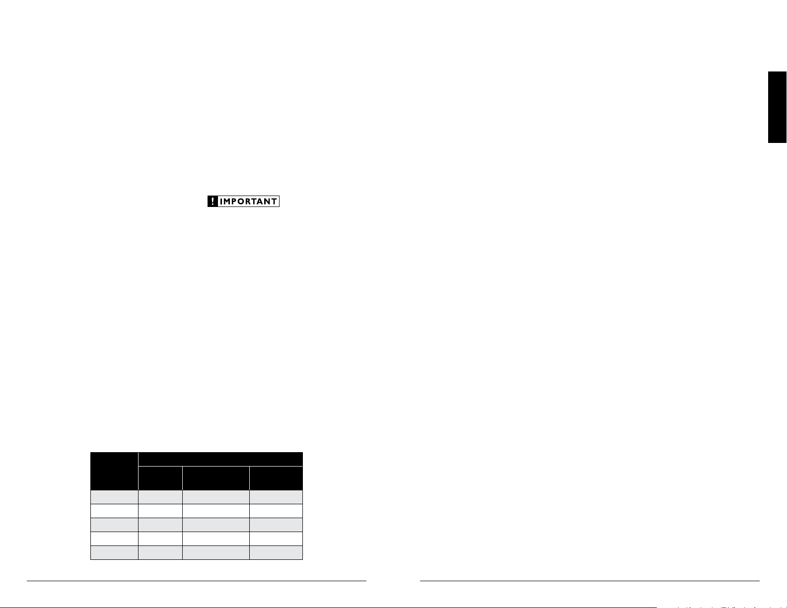
5) Using the chart on this page, determine the target
voltage for input sensitivity adjustment according
to the nominal impedance of the speaker system
connected to the amplifier outputs.
6) Verify that you have disconnected the speakers
before proceeding. Play a track with an
appropriate sine wave (within the frequency
range to be amplified by the channel you are
adjusting) at 3/4 source unit volume.
7) Connect the AC voltmeter to the speaker output
connectors of the amplifier. If the channel
pair is operating in stereo, it is only necessary
to measure one channel. If bridged, make sure
you test the voltage at the correct connectors
(L+ and R–).
8) Increase the “Input Sens.” control until the
target voltage is observed with the voltmeter.
9) Once you have adjusted each channel
sectio of the XD1000/5v2 to its maximum
low-distortion output level, reconnect the
speaker(s). The “Input Sens.” controls can
now be adjusted downward if the amplifier
requires attenuation to achieve the desired
system balance.
Do not increase any “Input Sens.” setting for
any amplifier channel or channel pair in the
system beyond the maximum level established
during this procedure. Doing so will result in
audible distortion and possible speaker damage.
It will be necessary to readjust the
“Input Sens.” for the affected channels if any
equalizer boost is activated after setting the
“Input Sens.” with this procedure. This applies
to any EQ boost circuit, including source unit
tone controls or EQ circuits. EQ cuts will not
require re-adjustment.
Due to ongoing product development, all specifications are subject to
change without notice.
Nom.
Impedance
Target AC Voltage
Main CH
(Stereo)
Main CH
(Bridged)
Subwoofer
CH
8
17.3 V 34.6 V 40.0 V
6
17.3 V 32.4 V 40.0 V
4
17.3 V 28.3 V 40.0 V
3
16.2 V not recommended 38.7 V
2
14.1 V not recommended 34.6 V
Loading ...
Loading ...
Loading ...