
Loading ...
Loading ...
Loading ...
10 | JL Audio - XD1000/5v2 Owner’s Manual
11
ENGLISH
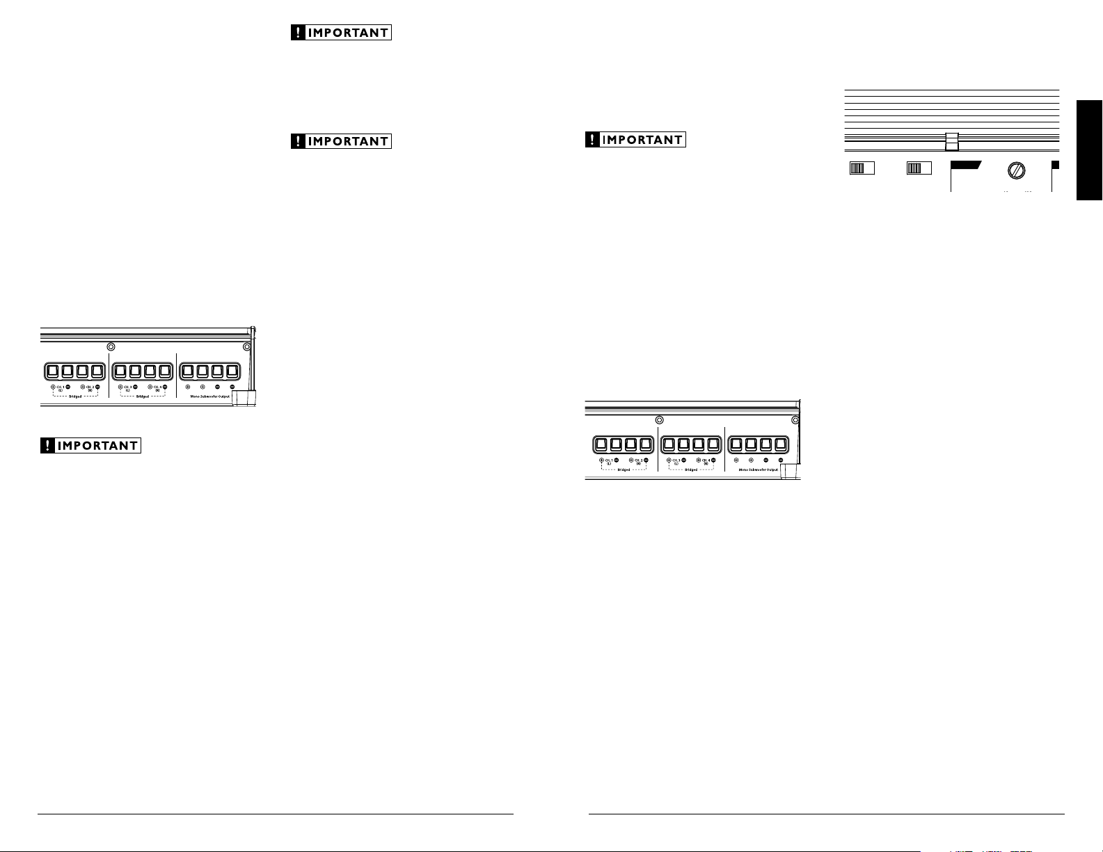
SUBWOOFER OUTPUTS
The XD1000/5v2’s single subwoofer channel
is designed to deliver power into subwoofer loads
equal to or greater than 2 ohms. It is rated for
600W into 2 ohms, 500W into 3 ohms and 400W
into 4 ohms (Continuous Power, RMS Method).
Subwoofer loads below 2 ohms nominal are not
recommended and may cause the amplifier
to initiate a protection mode which reduces
power output.
The XD1000/5v2’s subwoofer outputs are
designed to accept 16 AWG - 8 AWG wire. To
connect the subwoofer wires to the amplifier,
first back out the set screws on the top of the
terminal block, using the supplied 2.5 mm hex
wrench. Strip 1/2 inch (12 mm) of insulation
from the end of each wire and insert the bare
wire into the terminal block, seating it firmly
so that no bare wire is exposed. While holding
the wire in place, tighten the set screw firmly,
taking care not to strip the head of the screw.
You will notice that there are two “+” positive
connections and two “–” negative connections.
This is to facilitate multiple subwoofer wiring.
The two positive and two negative connections
are connected in parallel inside the amplifier
They are not stereo outputs. Connecting two
subwoofers, each to one set of positive and
negative terminals, will result in a parallel
subwoofer connection. If only connecting one
pair of subwoofer wires, it is not necessary to use
both sets of connections.
SPEAKER OUTPUTS
The XD1000/5v2’s speaker outputs are
designed to accept 16 AWG - 8 AWG wire. To
connect the speaker wires to the amplifier, first
back out the set screws on the top of the terminal
block, using the supplied 2.5 mm hex wrench.
Strip 1/2 inch (12 mm) of insulation from the
end of each wire and insert the bare wire into the
terminal block, seating it firmly so that no bare
wire is exposed. While holding the wire in place,
tighten the set screw firmly, taking care not to
strip the head of the screw.
Each pair of the XD1000/5v2’s main channels are
designed to deliver power into speaker loads equal
to or greater than 2 ohms when using a “stereo”
configuration and speaker loads equal to or greater
than 4 ohms when using a “bridged” configuration.
The subwoofer channel is designed to deliver power
into subwoofer loads equal to or greater than 2 ohms.
Speaker loads below 2 ohms nominal
per channel (or 4 ohms bridged) are not
recommended and may cause the amplifier
to initiate a protection mode which reduces
power output.
BRIDGING CONSIDERATIONS
Bridging is the practice of combining the
output of two amplifier channels to drive a single
load. When bridged, each channel produces
signals of equal magnitude, but opposite polarity.
The combined output of the two channels
provides twice the output voltage available from
a single channel. The XD1000/5v2 has been
designed for bridging of its main channel pairs
without the need for input inversion adaptors.
To bridge a pair of main channels, use the
“Left +” and “Right –” speaker connectors only
(the “Left –” and “Right +” remain unused). Each
bridged channel pair will deliver optimum power
into a 4 ohm load.
When a pair of the XD1000/5v2’s main
channels are bridged, they will deliver 200W x
1 into a 4 ohm load or 150W x 1 into an 8 ohm
load. Operating a pair of bridged channels into
a load lower than 4 ohms is not recommended.
A bridged pair of channels requires that both
channels in the pair receive input. You must
connect the mono or stereo source signal to
both the left and right inputs of the bridged
channel pair. Connection of only one input
will result in reduced power output, increased
distortion and can cause the amplifier to
overheat. Do not do this!
When a pair of the XD1000/5v2’s main
channels are operating in bridged mode, the
output will be in mono (only one channel). This
mono channel can contain only right channel
information, only left channel information, or
the sum of the signals from right and left input
channels. In order to achieve one of these options,
configure the inputs to that pair of channels in
one of these two ways:
1) Left Channel Only or Right Channel Only
Information: If you wish to send a left-only or
right-only signal to a pair of the XD1000/5v2’s
channels you must use a “Y-Adaptor” to split
the single channel signal into both left and
right RCA inputs of the bridged channel pair.
This option is used when deploying a pair of
the XD1000/5v2’s main channels to drive left
channel speakers only and the other pair of
the XD1000/5v2’s main channels to drive right
channel speakers only.
2) Left + Right Channel Information: When
bridged and fed by a stereo source signal, a
bridged pair of the XD1000/5v2’s channels will
automatically combine the left and right input
signals into a summed mono (left + right)
input signal.
STATUS LED / PROTECTION CIRCUITRY
There is a single multi-color LED on the top
surface of the amplifier to indicate the amplifier’s
operating status.
Remote
Level
Mode
Turn-On
Mode
All
|
Sub Ch.
Input Mode
2 Ch.
|
4 Ch.
|
6 Ch.
Rem.
|
Oset
|
Signal
Input Voltage
Low
|
High
CH. 3
(
L
)
CH. 4
(
R
)
CH. 1
(
L
)
CH. 1 & 2
CH. 3 & 4 SUB CH.
CH. 2
(
R
)
HP Filter Mode
Filter Freq. (Hz)
Input
Sens.
O
|
x1
|
x10
Filter Mode
HP Filter Freq. (Hz)
Input
Sens.
O
|
BP
|
HP
LP Filter Mode
LP Filter Freq. (Hz)
Input
Sens.
O
|
12dB
|
24dB
Mono Subwoofer Output
(
L
)
(
R
)
CH. 1
CH. 2
CH. 3
CH. 4
SUB
SUB
INPUT SECTION
+12 VDC Ground Remote
5 Channel Amplifier with 2-Way / 3-Way Crossover
1) Flashing Green: amplifier is powering up, audio
output is muted.
2) Constant Green: amplifier is on and functioning
normally, audio output is active.
3) Constant Red: Indicates that the amplifier has
exceeded its safe operating temperature, putting the
amplifier into a self-protection mode, which reduces
the peak power output of the amplifier. When its
temperature returns to a safe level, the red light will
return to green and the amplifier will return to full-
power operating mode.
4) Constant Amber (yellow): Indicates that an over-
current condition has occurred and is accompanied
by a muting of the affected channel(s). Because the
muting behavior may be very short in duration, it
may manifest itself as an audible, repetitive ticking
noise in the output. Over-current conditions can
be caused by a speaker impedance lower than the
optimum load impedance range for the amplifier or
a short-circuit in the speaker wiring. The latter can
result from a short circuit between the positive and
negative speaker wires or between either speaker
wire and the vehicle chassis. The “Status LED” will
remain amber for a few seconds, even if the over-
current condition is of a very short duration. This
functionality can be used to diagnose a short-circuit
by only connecting one channel at a time. The
“Status LED” will turn amber when you connect
the channel that is experiencing the problem and
turn the volume up.
5) LED off / Amplifier Shuts Off Unexpectedly
The only condition that will shut down
an undamaged XD1000/5v2 completely is if
battery voltage or remote turn-on voltage drops
below 10 volts. The “Status LED” will turn off
when this occurs. The amplifier will turn back on
when voltage climbs back above 11 volts. If this
is happening in your system, have your charging
system and power wiring inspected.
Loading ...
Loading ...
Loading ...