Loading ...
Loading ...
Loading ...
6 | JL Audio - XD1000/5v2 Owner’s Manual
7
ENGLISH
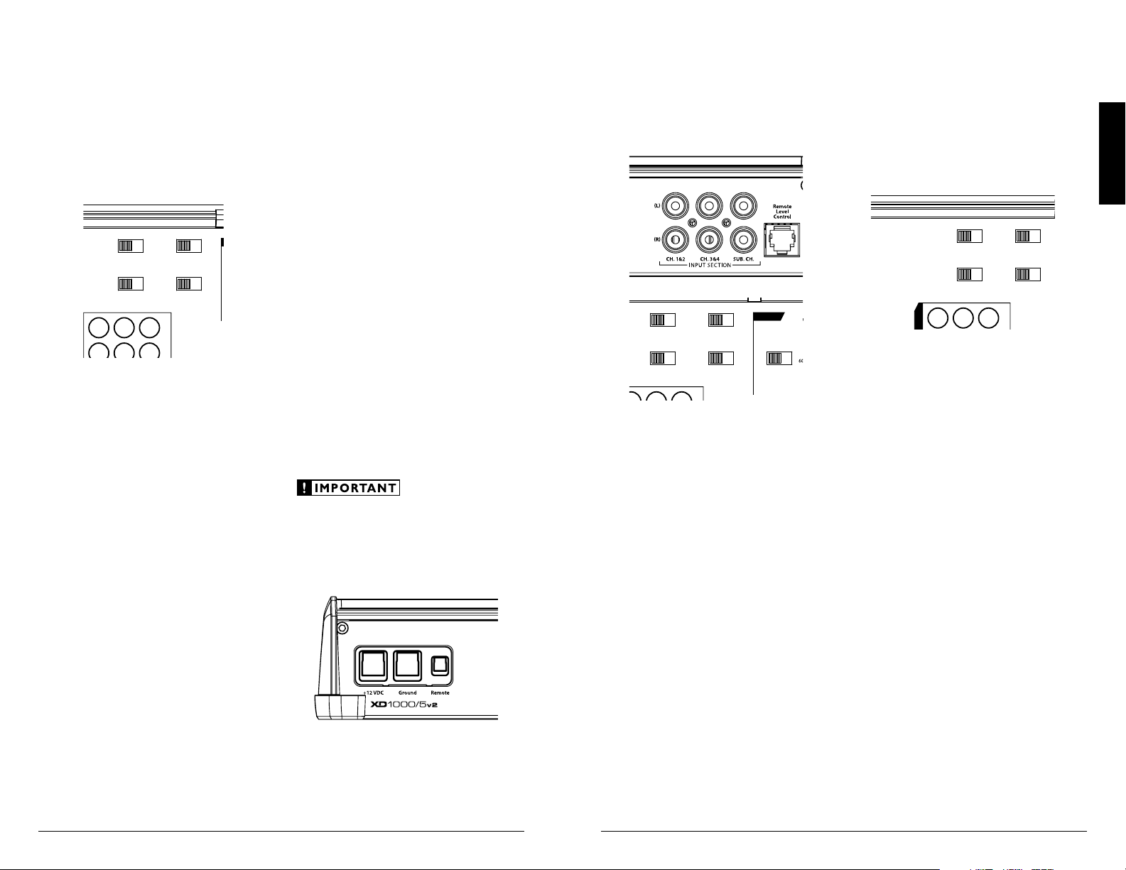
INPUT SECTION
The XD1000/5v2’s input section allows
you to send signals to the amplifier
section through the use of two, four or
six differential-balanced inputs.
Input connections are via up to three pairs of
traditional RCA-type jacks.
Remote
Level
Mode
Turn-On
Mode
All
|
Sub Ch.
Input Mode
2 Ch.
|
4 Ch.
|
6 Ch.
Rem.
|
Oset
|
Signal
Input Voltage
Low
|
High
CH. 3
(
L
)
CH. 4
(
R
)
CH. 1
(
L
)
CH. 1 & 2
CH. 3 & 4 SUB CH.
CH. 2
(
R
)
HP Filter Mode
Filter Freq. (Hz)
Input
Sens.
O
|
x1
|
x10
Filter Mode
HP Filter Freq. (Hz)
Input
Sens.
O
|
BP
|
HP
LP Filter Mode
LP Filter Freq. (Hz)
Input
Sens.
O
|
12dB
|
24dB
Mono Subwoofer Output
(
L
)
(
R
)
CH. 1
CH. 2
CH. 3
CH. 4
SUB
SUB
INPUT SECTION
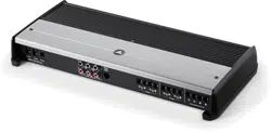
+12 VDC Ground Remote
5 Channel Amplifier with 2-Way / 3-Way Crossover
If you wish to send six discrete channels into the
XD1000/5v2, simply use all six inputs and set the
“Input Mode” switch in the “6 Ch.” position. The
amplifier will automatically combine the left and
right “Sub Ch.” input signals to mono. If you have
only one channel of subwoofer signal available,
it is acceptable to only use one of the “Sub Ch.”
inputs, but for optimal gain, we recommend using a
Y-adaptor and feeding both “Sub Ch.” inputs.
If you prefer to use only four channels of input
into the XD1000/5v2, set the “Input Mode” switch
in the “4 Ch.” position and use the Ch 1 & 2 and
Ch 3 & 4 Inputs. In this mode, the XD1000/5v2
will derive its subwoofer channel signal from a
sum of all four input signals. The bass will not
fade when the signal is faded by the head unit
from front to rear.
You may also choose to apply only two
channels of input to deliver signal to all five
amplifier channels. To do this, set the “Input
Mode” switch to “2 Ch.” and use only the inputs
to channels 1 & 2. In this mode, Channel 3 will
operate with the Channel 1 signal and Channel
4 will operate with the Channel 2 signal. The
amplifier will automatically combine the main
input signals to mono for the Subwoofer Channel.
Input Voltage Range:
Input Voltage Range: A wide range of signal
input voltages can be accommodated by the
XD1000/5v2’s input section (200mV – 8V).
This wide range is split up into two sub-ranges,
accessible via the “Input Voltage” switch:
“Low”: for preamp level signals
“High”: for speaker level signals
Remote
Level
Mode
Turn-On
Mode
All
|
Sub Ch.
Input Mode
2 Ch.
|
4 Ch.
|
6 Ch.
Rem.
|
Oset
|
Signal
Input Voltage
Low
|
High
CH. 3
(
L
)
CH. 4
(
R
)
CH. 1
(
L
)
CH. 1 & 2 CH. 3 & 4 SUB CH.
CH. 2
(
R
)
HP Filter Mode
Filter Freq. (Hz)
Input
Sens.
O
|
x1
|
x10
Filter Mode
HP Filter Freq. (Hz)
Input
Sens.
O
|
BP
|
HP
LP Filter Mode
LP Filter Freq. (Hz)
Input
Sens.
O
|
12dB
|
24dB
Mono Subwoofer Output
(
L
)
(
R
)
CH. 1
CH. 2
CH. 3
CH. 4
SUB
SUB
INPUT SECTION
+12 VDC Ground Remote
5 Channel Amplifier with 2-Way / 3-Way Crossover
The “Low” position on the “Input Voltage”
switch selects an input sensitivity range between
200mV and 2V for all input channels. This means
that the “Input Sens.” rotary control for each
channel section will operate within that voltage
window. If you are using an aftermarket source
unit, with conventional preamp-level outputs, this
is most likely the position that you will use.
The “High” position on the “Input Voltage”
switch selects an input sensitivity range between
800mV and 8V for all input channels. This is
useful for certain high-output preamp level
signals as well as speaker-level output from source
units and small amplifiers. To use speaker-level
sources, splice the speaker output wires of the
source unit or small amplifier onto a pair of RCA
cables or plugs or use the JL Audio ECS Speaker
Wire to RCA adaptor (XD-CLRAIC2-SW).
Line Output Converters are usually not needed
with the XD1000/5v2. If you find that the output
cannot be reduced sufficiently with a direct
speaker level signal applied to the amplifier and
the “Input Voltage” switch in its “High” position,
you may use a “line output converter” or voltage
divider to reduce the signal level.
TURNON OPTIONS
The XD1000/5v2 can be switched on and off
using one of three methods, determined by the
position of the amplifier’s “Turn-On Mode”
switch. Please read these options and decide
which is best suited for your specific system.
1) +12V remote turn-on lead
2) Signal-sensing turn-on circuit.
3) DC offset-sensing turn-on circuit
Remote
Level
Mode
Turn-On
Mode
All
|
Sub Ch.
Input Mode
2 Ch.
|
4 Ch.
|
6 Ch.
Rem.
|
Oset
|
Signal
Input Voltage
Low
|
High
CH. 3
(
L
)
CH. 4
(
R
)
CH. 1
(
L
)
CH. 1 & 2 CH. 3 & 4 SUB CH.
CH. 2
(
R
)
HP Filter Mode
Filter Freq. (Hz)
Input
Sens.
O
|
x1
|
x10
Filter Mode
HP Filter Freq. (Hz)
Input
Sens.
O
|
BP
|
HP
LP Filter Mode
LP Filter Freq. (Hz)
Input
Sens.
O
|
12dB
|
24dB
Mono Subwoofer Output
(
L
)
(
R
)
CH. 1
CH. 2
CH. 3
CH. 4
SUB
SUB
INPUT SECTION
+12 VDC Ground Remote
5 Channel Amplifier with 2-Way / 3-Way Crossover
+12 V Remote Turn-On: This is the preferred
method for turning the amplifier on/off. The
amplifier will turn on when +12 V is present at
its “Remote” input and turn off when +12 V is
switched off. This +12V remote turn-on signal is
typically controlled by a source unit’s remote
turn-on wire. The XD1000/5v2’s “Remote” turn-
on connector will accept 18 AWG – 12 AWG
wire. To connect the remote turn-on wire to
the amplifier, first back out the set screw on the
top of the terminal block, using the supplied 2.5
mm hex wrench. Strip 1/2 inch (12mm) of wire
and insert the bare wire into the terminal block,
seating it firmly so that no bare wire is exposed.
While holding the wire in the terminal, tighten
the set screw firmly, taking care not to strip the
head of the screw and making sure that the wire
is firmly gripped by the set screw.
If a source unit does not have a dedicated
remote turn-on output, consider one of the
following alternative turn-on options:
These methods are useful when a conventional
+12 V remote turn-on signal is not available in a
system. These allow you to operate the amplifier
without having to locate a remote turn-on lead at
the source unit, which can be very useful when
interfacing the amplifier with OEM (factory)
audio systems that do not use conventional +12 V
turn-on leads.
Depending on the characteristics of the audio
signal, one of the following methods may work
better than the other. We recommend trying DC
Offset-Sensing first as it does not require a long
delay to turn the system off after the signal is
shut off.
DC Offset-Sensing: The amplifier will turn on
and off by detecting the presence of a very small
DC signal (offset) that is typical in the audio
output of most OEM (factory) source units and
amplifiers. The amplifier will turn on and off in
reaction to the presence or absence of this DC
Offset. The sensitivity of this circuit is designed
for high-level (speaker level) signals, not for low-
level (preamp level) signals. The circuit senses the
“Ch. 1” (left) input signal only.
Signal-Sensing: The amplifier will turn on
and off by detecting the presence of a full-range
audio signal at its “Ch 1” (left) input. After several
minutes of no signal, the amplifier will shut off.
The sensitivity of this circuit is designed for
high-level (speaker level) signals, not for low-level
(preamp level) signals. The circuit is tuned to
react to signals at mid-range frequencies. This
prevents false switching from signals created by
moving loudspeakers that are in parallel with the
amplifier’s input signal.
In signal and DC sensing applications, the
amplifier’s “Remote” turn-on terminal becomes
a remote turn-on output. This allows the
XD1000/5v2 to turn on other amplifiers in the
audio system that do not have signal sensing.
Loading ...
Loading ...
Loading ...