Loading ...
Loading ...
Loading ...
8 | JL Audio - XD1000/5v2 Owner’s Manual
9
ENGLISH
Channel 3 & 4 Filter: 12dB/octave High-Pass
or Bandpass Filter
“Off”: Defeats the filter completely, allowing
the full range of frequencies present at the inputs
to feed these channels. This is useful for systems
utilizing outboard active crossovers or requiring
full-range reproduction from this channel pair.
“BP” (High-Pass): Configures the filter to
attenuate frequencies below the indicated filter
frequency AND above the Channel 1 & 2 Filter
Frequency, at a rate of 12dB per octave. This is
useful for connection of mid-bass or mid-range
speakers in a tri-amplified system.
“HP” (High-Pass): Configures the filter
to attenuate frequencies below the indicated
filter frequency at a rate of 12dB per octave.
This is useful for connection of component
speakers or coaxials to this channel pair in a
bi-amplified system.
Subwoofer Channel Filter: 12dB/octave
or 24dB/octave, Low-Pass only
“Off”: Defeats the filter completely, allowing
the full range of frequencies present at the inputs
to feed this channel. This is useful for systems
utilizing outboard active crossovers.
“12dB” (Low-Pass): Configures the filter
to attenuate frequencies above the indicated
filter frequency, at a rate of 12dB per octave.
This is useful for connection of subwoofers in a
bi-amplified system. This shallower slope gently
attenuates high-frequencies from your subwoofer
signal and is often well-suited for sedans and
coupes with trunks.
“24dB” (Low-Pass): Configures the filter
to attenuate frequencies above the indicated
filter frequency, at a rate of 24dB per octave.
This is useful for connection of subwoofers in
a bi-amplified system. This sharper slope more
aggressively removes high-frequencies from your
subwoofer signal and is often well-suited for
SUV’s, wagons and hatchbacks.
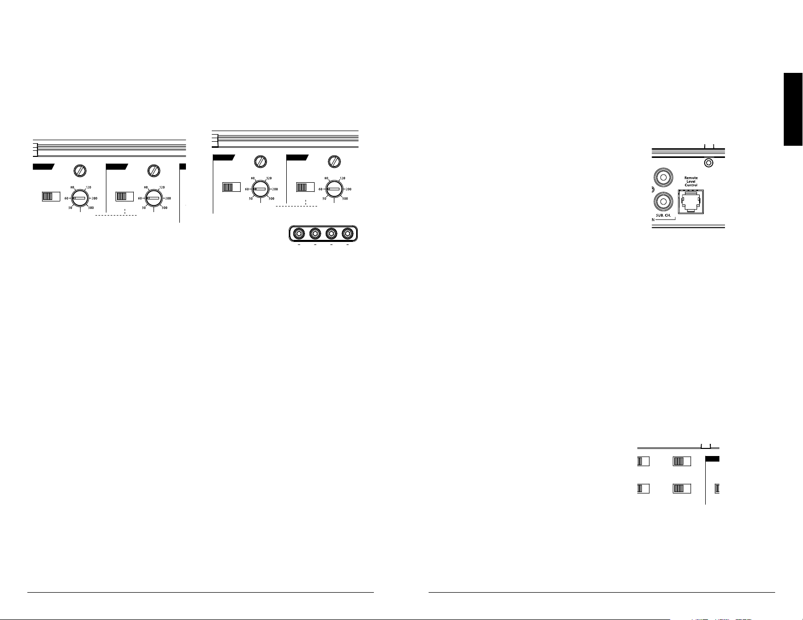
2) “Filter Freq. (Hz)” The filter frequency
markings surrounding these rotary controls
(one in each Channel Section) are for reference
purposes and are generally accurate to within
1/3 octave or better. If you would like to select
the filter cutoff frequency with a higher level
of precision, consult the chart in Appendix B
(page 15).
Tuning Hint: If you are using the XD1000/5v2
to drive a subwoofer system (“LP” mode), and
component satellite speaker systems (“HP” mode),
80 Hz is a good baseline “Filter Freq. (Hz)” setting.
After properly adjusting the “Input Sens.”, as
outlined in Appendix A (page 14), you can fine
tune the “Filter Freq. (Hz)” control to achieve the
desired system frequency response.
REMOTE LEVEL CONTROL OPTIONAL
With the addition of the optional Remote Level
Control (HD-RLC), you can control the volume of
the subwoofer channel (Subwoofer Level) or of the
entire XD1000/5v2 from the front of the vehicle
(Master Volume).
The HD-RLC connects to the jack labeled
“Remote Level Control” on the Connection Panel
of the amplifier using a standard telephone cable
(supplied with the HD-RLC). If desired, multiple
XD (and HD) amplifiers can be controlled from
a single HD-RLC controller using a simple non-
duplex, single line, phone cable “splitter” and
multiple phone cables.
When connected to the amplifier, the HD-RLC
operates as follows. At full counter-clockwise
rotation, the audio of the selected channels will
mute completely. At full clockwise rotation the
level will be the same as if the HD-RLC was not
connected at all. In other words, it operates strictly
as a level attenuator.
Remote
Level
Mode
Turn-On
Mode
All
|
Sub Ch.
Input Mode
2 Ch.
|
4 Ch.
|
6 Ch.
Rem.
|
Oset
|
Signal
Input Voltage
Low
|
High
CH. 3
(
L
)
CH. 4
(
R
)
CH. 1
(
L
)
CH. 1 & 2 CH. 3 & 4 SUB CH.
CH. 2
(
R
)
HP Filter Mode
Filter Freq. (Hz)
Input
Sens.
O
|
x1
|
x10
Filter Mode
HP Filter Freq. (Hz)
Input
Sens.
O
|
BP
|
HP
LP Filter Mode
LP Filter Freq. (Hz)
Input
Sens.
O
|
12dB
|
24dB
Mono Subwoofer Output
(
L
)
(
R
)
CH. 1
CH. 2
CH. 3
CH. 4
SUB
SUB
INPUT SECTION
+12 VDC Ground Remote
5 Channel Amplifier with 2-Way / 3-Way Crossover
“Remote Level Mode” Switch: This switch allows
you to assign the operation of the HD-RLC to the
entire amplifier or only the subwoofer channel. In
the “All” position, the HD-RLC knob will affect all
channels equally. In the “Sub Ch.” position, only
the level of the subwoofer channel will be affected
by the HD-RLC knob.
INPUT SENSITIVITY CONTROLS
The controls labeled “Input Sens.” located
in each channel section can be used to match
the source unit’s output voltage to the input
stage of each channel bank for maximum clean
output. Rotating the control clockwise will result
in higher sensitivity (louder for a given input
voltage). Rotating the control counter-clockwise
will result in lower sensitivity (quieter for a given
input voltage.)
Remote
Level
Mode
Turn-On
Mode
All
|
Sub Ch.
Input Mode
2 Ch.
|
4 Ch.
|
6 Ch.
Rem.
|
Oset
|
Signal
Input Voltage
Low
|
High
CH. 3
(
L
)
CH. 4
(
R
)
CH. 1
(
L
)
CH. 1 & 2
CH. 3 & 4
SUB CH.
CH. 2
(
R
)
HP Filter Mode
Filter Freq. (Hz)
Input
Sens.
O
|
x1
|
x10
Filter Mode
HP Filter Freq. (Hz)
Input
Sens.
O
|
BP
|
HP
LP Filter Mode
LP Filter Freq. (Hz)
Input
Sens.
O
|
12dB
|
24dB
Mono Subwoofer Output
(
L
)
(
R
)
CH. 1
CH. 2
CH. 3
CH. 4
SUB
SUB
INPUT SECTION
+12 VDC Ground Remote
5 Channel Amplifier with 2-Way / 3-Way Crossover
To properly set the amplifier for maximum
clean output, please refer to Appendix A (page
14) in this manual. After using this procedure,
you can then adjust any or all “Input Sens.”
levels downward if this is required to achieve the
desired system balance.
Do not increase any “Input Sens.” setting for
any channel(s) of any amplifier in the system
beyond the maximum level established during
the procedure outlined in Appendix A (page 14).
Doing so will result in audible distortion and
possible speaker damage.
FILTER CONTROLS
Most speakers are not designed to reproduce
the full range of frequencies audible by the human
ear. For this reason, most speaker systems are
comprised of multiple speakers, each dedicated
to reproducing a specific frequency range. Filters
are used to select which frequency range is sent to
each section of a speaker system. The division of
frequency ranges to different speakers can be done
with passive filters (coils and/or capacitors between
the amplifier outputs and the speakers), which
are acceptable and commonly used for filtering
between mid-range speakers and tweeters. Filtering
between subwoofer systems and satellite speaker
systems is best done with active filters, which cut
off frequency content at the input to the amplifier.
Active filters are more stable than passive filters
and do not introduce extraneous resistance, which
can degrade subwoofer performance.
The active filter built into each channel section
of the XD1000/5v2 can be used to eliminate
potentially harmful and/or undesired frequencies
from making their way through the amplifier
sections to the speaker(s). This serves to improve
tonal balance and to avoid distortion and possible
speaker failure. Correct use of these filters can
substantially increase the longevity and fidelity of
your audio system.
Remote
Level
Mode
Turn-On
Mode
All
|
Sub Ch.
Input Mode
2 Ch.
|
4 Ch.
|
6 Ch.
Rem.
|
Oset
|
Signal
Input Voltage
Low
|
High
CH. 3
(
L
)
CH. 4
(
R
)
CH. 1
(
L
)
CH. 1 & 2
CH. 3 & 4
SUB CH.
CH. 2
(
R
)
HP Filter Mode
Filter Freq. (Hz)
Input
Sens.
O
|
x1
|
x10
Filter Mode
HP Filter Freq. (Hz)
Input
Sens.
O
|
BP
|
HP
LP Filter Mode
LP Filter Freq. (Hz)
Input
Sens.
O
|
12dB
|
24dB
Mono Subwoofer Output
(
L
)
(
R
)
CH. 1
CH. 2
CH. 3
CH. 4
SUB
SUB
INPUT SECTION
+12 VDC Ground Remote
5 Channel Amplifier with 2-Way / 3-Way Crossover
1) “Filter Mode” Controls: The XD1000/5v2
employs 12dB per octave filters for each pair
of main channels (one high-pass filter for
channels 1&2 and another high-pass / bandpass
filter for channels 3&4. The Subwoofer Channel
provides a low-pass filter with the option of
12dB or 24dB / octave slopes. Each of these
filters can be controlled or defeated completely
by way of the three-position “Filter Mode”
switches in each Channel Section:
Channel 1 & 2 Filter: 12dB/octave High-Pass
only, with x10 multiplier switch
“Off”: Defeats the filter completely, allowing
the full range of frequencies present at the inputs
to feed these channels. This is useful for systems
utilizing outboard active crossovers or requiring
full-range reproduction from this channel pair.
“x1” (High-Pass): Configures the filter
to attenuate frequencies below the indicated
filter frequency at a rate of 12dB per octave.
This is useful for connection of component
speakers or coaxials to this channel pair in a
bi-amplified system.
“x10” (High-Pass): Configures the filter to
attenuate frequencies below a frequency TEN
TIMES HIGHER than the indicated filter
frequency, at a rate of 12dB per octave. This is
useful for connection of tweeters to this channel
pair in a tri-amplified system.
Loading ...
Loading ...
Loading ...