Loading ...
Loading ...
Loading ...
Page 8
TV Installation – Rear Panel Internal Connect Source - Cable routing
WARNING: Do not connect the power source before making connections.
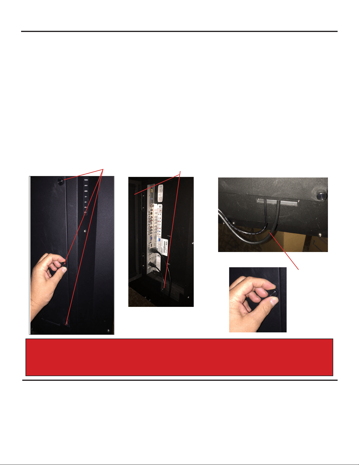
Internal Connect Source through the cable access door.
The Internal Connect Source allows you to easily connect to the Audio, Video, VGA, HDMI, Audio Out, and RF connectors. The
internal connect Source are inside the cable cover located on the back of the unit (Figure1).
1. Unscrew the two Thumb Screws (Figure1), and pull the cover towards you.
2. Route the cables to the proper inputs, and place the cable cords over the Rubber Sealing Gasket on the bottom of the cable
access opening(Figure 2).
3. Be sure the cables are routed past the indentation on the bottom of the door. Cable cannot be routed through the top and side
of the rubber sealing gasket. (Figure 3).
3. Close the cover. Route the cables as shown to provide a drip loop below the door. This will prevent water from dripping down
the cord and possibly entering the door area.
4. Press rmly on the cover, and screw the Thumb Screws tightly (Figure4).
Figure 1
Figure 2
Figure 4
Rubber Sealing Gasket
Thumb Screws
TV Installation - Connecting the Power Cord
Do not connect power cord until all cable connections have been made.
Connect the power cord to a GFCI protected AC outlet with an “in-use” waterproof cover.
WARNING:
TV AND GFCI RECEPTACLE MUST BE INSTALLED AT LEAST 5 FEET AWAY FROM STANDING WATER , SUCH AS (BUT NOT LIMITED
TO) A POOL OR SPA. BE SURE TO CHECK LOCAL ELECTRICAL CODES AND COMPLY WITH THEIR LOCAL STANDARDS.
Route cables trough the
bottom of the door only
Figure 3
Drip Loop
Warning: Do not route cable from the top or sides of the cable access door. This
will prevent a proper seal of the cable compartment and will void your warranty.
Loading ...
Loading ...
Loading ...