
Loading ...
Loading ...
Loading ...
Service Manual: SC750, SC800, SC 750 ST, SC800 ST
Form Number 56043150 Page 51
Specifications
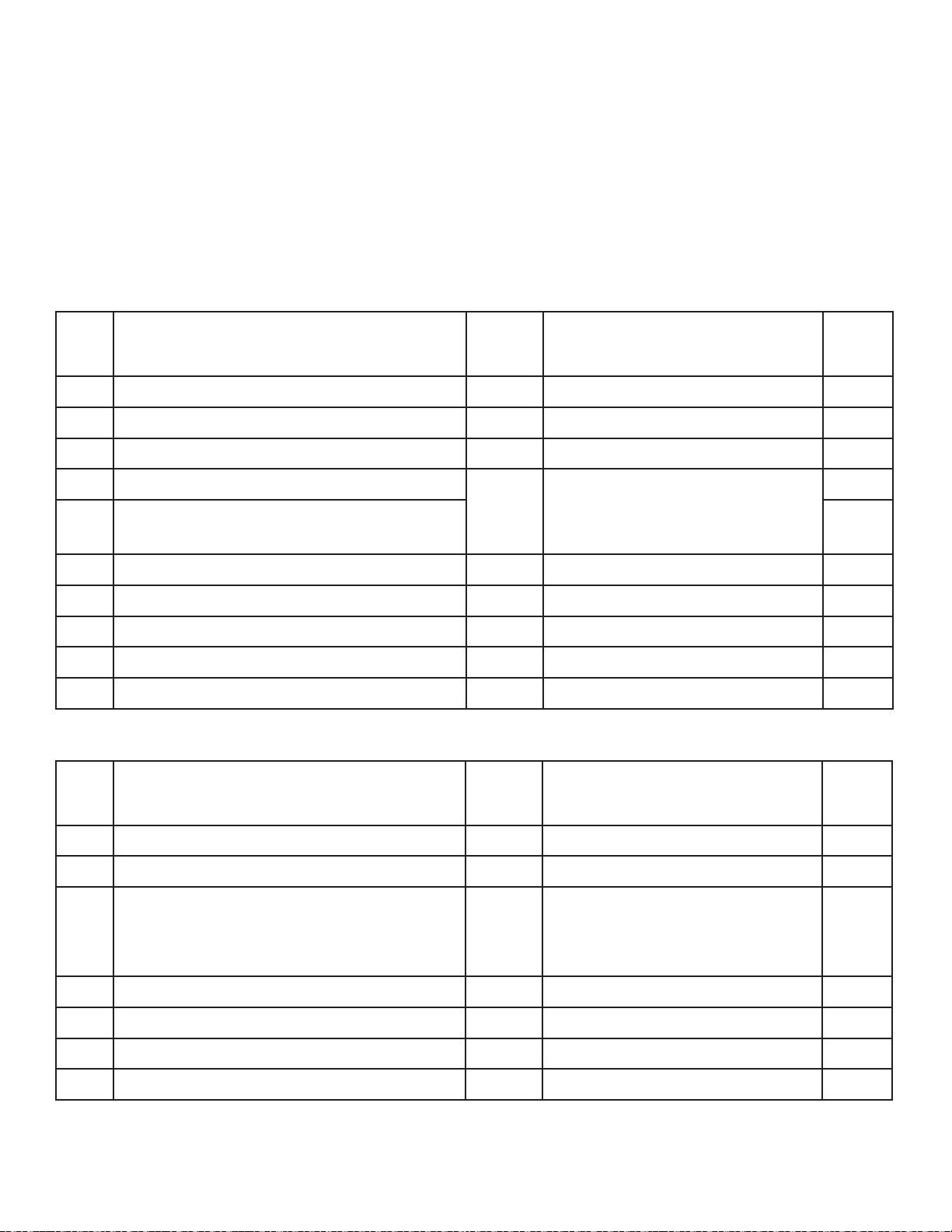
Shop Measurements – Main Machine Controller
The following tables contain some “real world” shop voltage measurements to help you recognize what “normal” looks
like. All voltage values were measured with the black (Negave) voltmeter lead connected to the main baery negave
terminal unless otherwise specied. (Non ST = SC750 and SC800 models. ST = SC750 ST and SC800 ST models)
J1 Connector
Pin # Circuit Descripon Value Comments
Used
on Non
ST or ST
1 Chemical Pump “+” output Non ST
2 Not used Both
3 Chemical Pump “-“ output Non ST
4 Brush Head Actuator motor “+” output 24v
down
-24v up
With red lead at pin #4 and black
lead at pin #5
Both
5 Brush Head Actuator motor “-“ output Both
6 Not used Both
7 Not used Both
8 Baery Negave (Ground) 0.5mV With vacuum motor running Both
9 Not used Both
10 Not used Both
J2 Connector
Pin # Circuit Descripon Value Comments
Used
on Non
ST or ST
1 Baery Negave (Ground) 0.5mV With vacuum motor running Both
2 Baery Negave (Ground) 0.5mV With vacuum motor running Both
3 Input from Brush Deck actuator posion switch
#0. Switch oats open when actuator is fully
retracted (corresponding to a raised deck), and
is closed to GND otherwise.
4.95V Up Posion. Other posions 0.5mV Both
4 Not used Both
5 Not used Both
6 Not used Both
7 Baery Negave (Ground) 0.5mV With vacuum motor running Both
Loading ...
Loading ...
Loading ...