Loading ...
Loading ...
Loading ...
12
Enfoncer et tenir
le bouton STOP...
...Enfoncer et tenir ensuite
le bouton « CLOSE »…
...Enfoncer et tenir ensuite le bouton « OPEN »
jusqu’à ce que la mention « Er » s’affiche.
LEARN
DIAGNOSTICS
OPEN
LEFT
OPEN
RIGHT
HANDING
SET OPEN
MOVE
GATE
XMITTER
NETWORK
SET CLOSE
D’OUVERTURE DROIT
RÉGLAGE DE
FERMETURE
Cartes c.a. Cartes c.c.
ENFONCER ET
RELÂCHER POUR
COMMENCER LA
CONFIGURATION
DE LA LIMITE
Appuyer sur le bouton
d’ouverture (OPEN)
pour passer au code
le plus récent (« 01 »).
Appuyer sur le bouton
de fermeture (CLOSE)
pour passer au code
le plus ancien
(jusqu’à « 20 »).
13. I2C communication problems (codes AD and AE).
a. Reasons for I2C communication loss.
i. Observe the power LED on the expansion board. If it is not flashing once a second, than an I2C communication problem is likely. The power LED is oriented under the I2C interface board as
installed. If the Data LED is not flashing, press and release the mainboard STOP button to wake the system.
ii. Bad connections on the wires.
1. A loose pin on one of the harness might not make a good electrical connection to one of the boards.
a. Replace to suspect harness to see if the problem goes away.
b. Plug the receiver directly into the main board to see if the problem goes away.
iii. Wires not correctly installed.
1. Inspect the wire harness to ensure that the plugs are correctly inserted over the jacks pin for pin.
iv. I2C Interface board not correctly installed.
1. Make sure that the plug on the bottom of the I2C interface board is correctly installed on the corresponding jack on the expansion board. This is a frequent occurrence to this problem.
v. Accessory (LOOPDETLM).
1. Remove all accessories from the expansion board and connect them to the main board. See if the problem goes away.
2. Substitute the LOOPDETLM with an external loop detector to see if the problem goes away.
vi. Bad boards.
1. A bad I2C interface board, main logic board or expansion board can cause this problem but is infrequent. Exhaust all other steps before changing boards.
vii. All (or some) of the above.
1. Be open to the possibility that more than one problem may exist. A loose pin on the expansion board coupled with electrically noisy LED lights may both be influencing the performance of the
LMWEKITU at the same time. Work each issue individually until all LMWEKITU advanced diagnostics stop logging.
CODES DE DIAGNOSTIC AVANCÉ
10. Codes de diagnostic avancé (utilisés lorsque le code de diagnostic 68 a été journalisé).
a. Afin d’utiliser les codes de diagnostic avancé, le micrologiciel doit être de version 3.5 ou plus. Noter que les versions antérieures peuvent afficher des codes de diagnostic avancé; toutefois, elles
n’incluront pas ces codes liés au rendement de la bordure sans fil. Détermination de la version logicielle de la carte.
i. Actionneurs c. c. :
1. Retirer le connecteur du chargeur s’il a été installé.
2. Débrancher le connecteur J-15 de la carte mère.
3. Attendre 20 secondes.
4. Brancher le connecteur J15 et observer l’affichage à sept segments.
5. Brancher le connecteur du chargeur s’il était installé.
ii. Actionneurs c. a. :
1. Débrancher le connecteur IN de 24 V c. a. de la carte mère.
2. Attendre 20 secondes.
3. Brancher le connecteur IN de 24 V c. a. et observer l’affichage à sept segments.
iii. L’écran d’affichage à sept segments fera clignoter une série de trois affichages. Le troisième affichage sera un numéro de version et peut être identifié par un point décimal entre le premier et le
deuxième chiffre. Par exemple, si la séquence de départ affiche « LA », puis « 40 », suivi par « 3.5 », la version de la carte est 3.5.
b. Passage en mode de diagnostic
i.
L’actionneur montrera le numéro de séquence du code suivi du numéro du code.
c. Passage en mode diagnostic avancé.
i. Actionneurs c. a. :
1. Enfoncer et tenir le bouton d’ouverture droit.
2. « Ad » s’affichera sur l’écran à sept segments.
3. Relâcher le bouton d’ouverture droit.
ii. Actionneurs c. c. :
1. Enfoncer et tenir le bouton de réglage de fermeture.
2. « Ad » s’affichera sur l’écran à sept segments.
3. Relâcher le bouton de réglage de fermeture.
d. Défiler dans les codes de diagnostic.
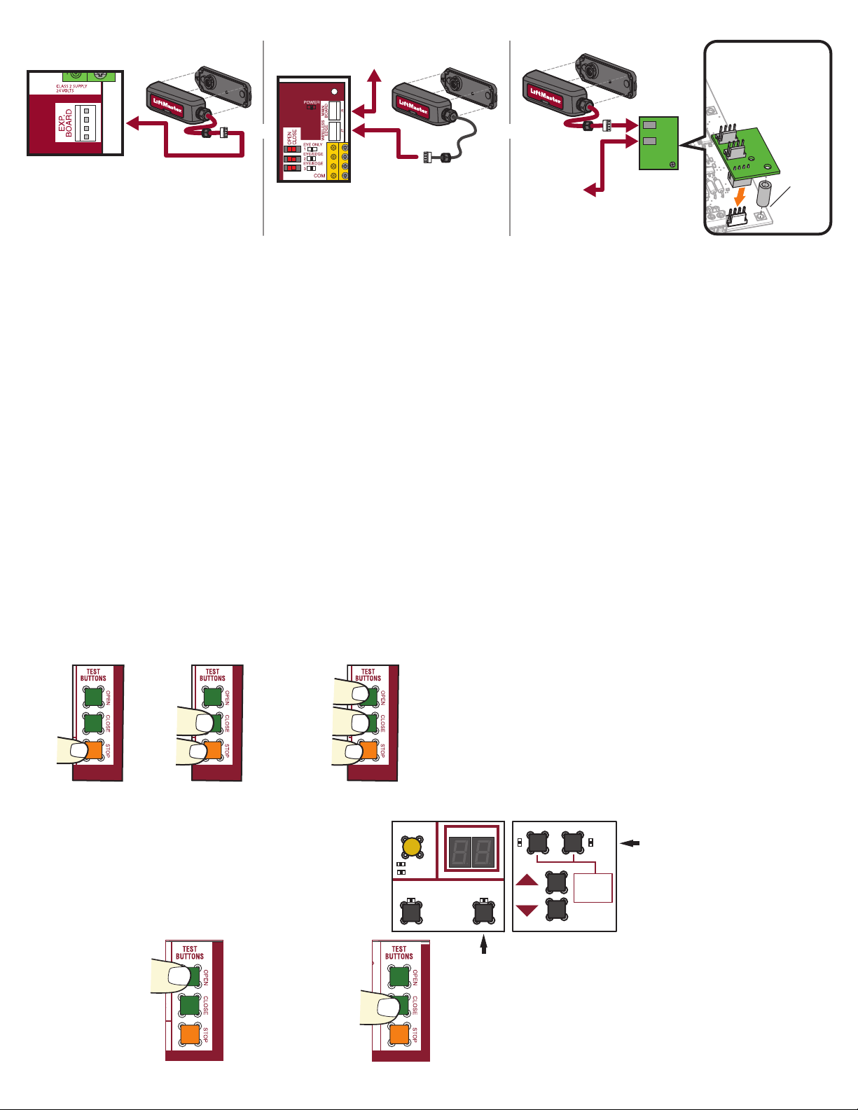
To Main
Control Board
Expansion Board
To Main Control Board
Control Board
I2C Interface Board
Check all wires between the
receiver and main board,
including the expansion board
(if applicable). Wiggle the wires
to check for intermittent connection.
Check all wires between the
receiver and expansion board, and
the expansion board and main
board. Wiggle the wires to check
for intermittent connection.
Make sure that the I2C
interface board is correctly
installed pin for pin and that
the power LED is flashing
1 time per second.
Remove LOOP DET LM
modules from
expansion
board to
see if the
problem
goes away.
OR OR
Loading ...
Loading ...
Loading ...