Loading ...
Loading ...
Loading ...
10
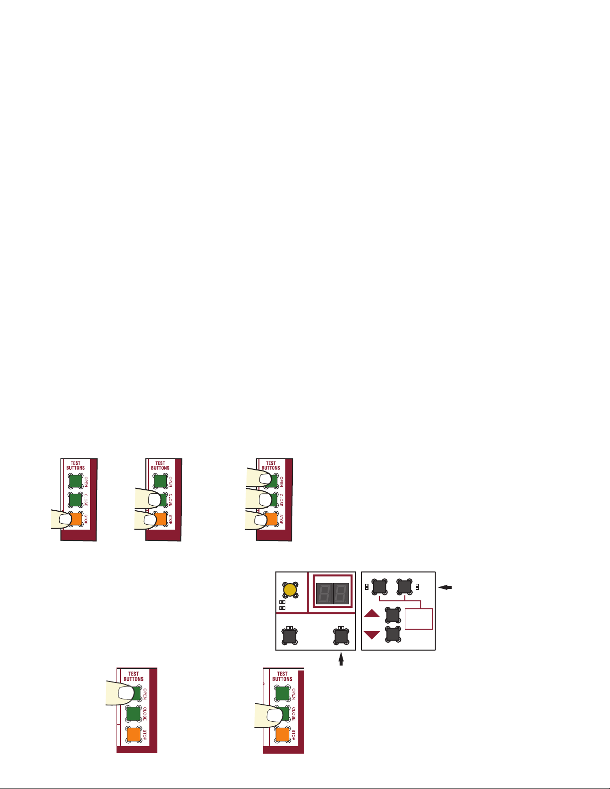
Press and hold the
STOP button...
...then press and hold
the CLOSE button...
...then press and hold the OPEN button
until "Er" shows on the display.
LEARN
DIAGNOSTICS
OPEN
LEFT
OPEN
RIGHT
HANDING
SET OPEN
MOVE
GATE
XMITTER
NETWORK
SET CLOSE
OPEN RIGHT
SET CLOSE
AC Boards DC Boards
PRESS &
RELEASE TO
BEGIN LIMIT
SETUP
CONFIGURACIÓN Y PRUEBAS INDIVIDUALES
5. Cómo verificar el circuito supervisor en el borde.
a. Abra las tapas del borde y asegúrese de que tanto el enchufe del contacto a un lado del borde como el resistor del monitor en el otro lado del borde estén instalados correctamente y sus cables no
estén corroídos. Reemplace las partes en el borde una vez que termine.
b. Retire el bloque de terminales del conector.
c. Retire los cables de los bloques de terminales.
d. Mida la resistencia entre los dos cables que van al borde.
e. La resistencia debería ser de 8.0kΩ a 8.4kΩ sin oprimir el borde.
i. Si la lectura es abierta (ohmios infinitos), falta el resistor supervisor o está incorrectamente instalado.
ii. Si la lectura es inferior a 100Ω, el borde está defectuoso.
f. Presione (apriete) el borde.
g. La resistencia debería caer por debajo de 100Ω.
i. Si la lectura es superior a 100Ω, el borde está defectuoso. Reemplace el borde.
h. Asegúrese de que el interruptor de borde correspondiente esté configurado para la dirección correcta de desplazamiento en la que el borde debe detectar el atrapamiento. Si se cambia el interruptor
después de la programación, deberá volver a programar el borde en el operador siguiendo el paso 7).
6. Cómo desprogramar el transmisor del receptor.
a. Mantenga presionado el botón de aprendizaje del RECEPTOR hasta que el LED de estado rojo empiece a parpadear. Mantenga presionado el botón de aprendizaje hasta que se apague el LED
(aproximadamente 10 segundos) y luego suéltelo. El operador de portón emitirá un sonido durante 5 segundos para confirmar que todos los transmisores se hayan borrado.
7. Cómo desprogramar el receptor del operador.
a. Operadores de CC:
i. Presione y suelte los interruptores de límite de apertura/cierre al mismo tiempo para entrar al modo límite de aprendizaje.
ii. Presione y suelte los interruptores de límite de apertura/cierre para salir del modo límite de aprendizaje.
iii. Los dispositivos de atrapamiento serán eliminados (todos los sensores fotoeléctricos y los bordes monitoreados programados).
b. Operadores de CA:
i. Presione y suelte los botones manuales de apertura derecho y de apertura izquierdo a la misma vez.
ii. Presione y suelte los botones manuales de apertura derecho y de apertura izquierdo una segunda vez.
iii. Los dispositivos de atrapamiento serán eliminados (todos los sensores fotoeléctricos y los bordes monitoreados programados).
c. Tenga en cuenta que los tableros volverán a programar los dispositivos de seguridad tan pronto como se instalen en el operador.
8. Cómo programar el transmisor al receptor.
a. Presione el botón de aprendizaje en el tablero RECEPTOR. El DEL rojo se encenderá para indicar que el modo de programación está activado. NOTA: Para salir del modo de programación, vuelva a
presionar el botón de aprendizaje.
9. Cómo probar la activación del borde.
a. En el transmisor, el LED rojo debería parpadear al presionar el borde, y de nuevo al soltarlo.
b. En el receptor, el LED rojo debería parpadear al presionar el borde, y parpadeará aproximadamente cinco segundos al soltar el borde.
c. En el tablero lógico, el borde de cierre o el borde de apertura (dependiendo de la configuración del interruptor del transmisor) parpadeará al apretar el borde, hasta aproximadamente 5 segundos
después de soltar el borde.
ADVANCED DIAGNOSTIC CODES
10. Advanced Diagnostic Codes (used when diagnostic code 68 is logged).
a. In order to utilize advanced diagnostic codes, the firmware version of the board must be 3.5 or higher. Note that earlier versions may display advanced diagnostic codes, however they will not include
those codes that are related to wireless edge performance. To determine the firmware version of the board.
i. DC operators:
1. Remove the charger connector if installed.
2. Unplug the J-15 connector from the main board.
3. Wait for 20 seconds.
4. Plug in the J15 connector and observe the seven segment display.
5. Plug in the charger connector if it was installed.
ii. AC operators:
1. Unplug the 24VAC IN connector from the main board.
2. Wait for 20 seconds.
3. Plug in the 24VAC IN connector and observe the seven segment display.
iii. The seven segment display will flash a series of three displays. The third display will be the version number, and can be identified with a decimal point between the first and second digits. For example,
if the startup display sequence displays “LA” then “40” followed by “3.5”, the version of the board is 3.5.
b. Enter Diagnostic Mode
i.
The operator will show the code sequence number followed by the code number.
c. Enter the advanced diagnostic mode.
i. AC operators:
1. Press and hold the Open Right button.
2. “Ad” will be shown on the seven segment display.
3. Release the Open Right button.
ii. DC operators:
1. Press and hold the Set Close button.
2. “Ad” will be shown on the seven segment display.
3. Release the Set Close button.
d. Scroll through the diagnostic codes.
Press the OPEN button
to cycle to the most
recent code ("01").
Press the CLOSE button
to cycle to the oldest
code (up to "20").
Loading ...
Loading ...
Loading ...