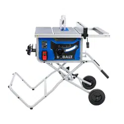
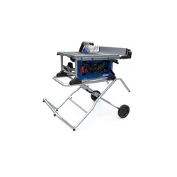
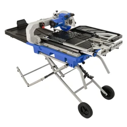
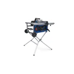
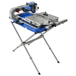
User manual Portable Table Saw
ASSEMBLY INSTRUCTIONS
UNPACKING
1. Cut sides of box at all four corners. IMPORTANT: Before assembly, separate upper and lower packing trays. Leave base section in lower tray while completing steps 1 - 8.
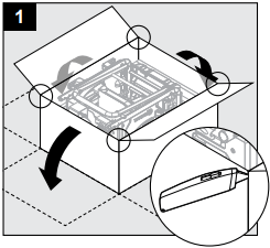
TABLE STAND ASSEMBLY
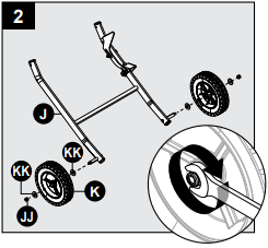
2. First remove washers (KK) and nuts (JJ) from lower right leg assembly, then attach wheels (K) to lower right leg assembly (J) with washers (KK) (one on each side of wheel) and nut (JJ). Check orientation of wheels and if wheels rub against frame, reverse orientation. Set wheel assembly aside for later use.
Hardware Used

3. Attach left leg cross piece (R) to left front leg (M) and left rear leg (N) with M6 x 50 bolts (CC).

Hardware Used

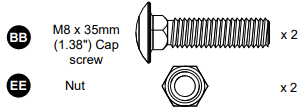
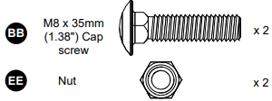
4. Attach left leg end (S) onto the leg assembly from step 3. Secure with M8 x 35mm (1.38"). cap screw (BB) and nut (EE).
Note: The feet on the left leg end (S) should face to the outside (left).

Hardware Used
5. With table (V) still in lower packing tray, attach two handles (I1 & I2) to table (V) with 1-1/2 in. cap screw (BB) and nut (EE).
Note: Square and round holes can be aligned together.
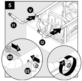
Hardware Used
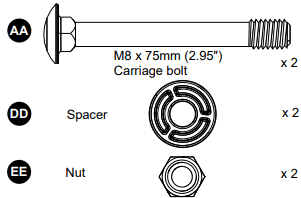
6. Attach leg assembly to table (V). Insert spacer (DD) between legs and secure with M8 x 75mm (2.95") carriage bolt (AA) and nut (EE).
Note: Cut zip tie securing the pre-assembled upper leg in place.

Hardware Used

7a. Install the wheel assembly from step 2 to leg assembly installed in step 6. Insert spacer (DD) between legs and secure with M8 x 75mm (2.95") carriage bolt (AA) and nut (EE)
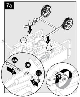
Hardware Used
7b. Raise the narrowest part of the stand to help align the holes. Insert spacer (DD) between legs and secure with M8 x 75mm (2.95") cap screw (AA) and nut (EE).
Note: DO NOT overtighten. Cut zip tie securing pedal.

Hardware Used

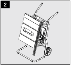
8. Grasp handles and tilt table saw back onto wheels. Remove table saw from packing tray. Let machine "stand" and tighten all screws.
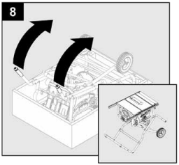
9. IMPORTANT: Release height adjustment locking lever and tilt blade to 45˚ to release and remove packing material under motor.

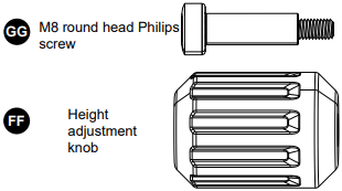
10. Install height adjustment knob (FF) and M8 round head Philips screw (GG) to height adjustment wheel.

Hardware Used
RIVING KNIFE INSTALLATION AND POSITIONING
Note: This saw is shipped with riving knife in lowered position for non-through cuts. Riving knife must be placed in raised position to attach anti-kickback pawls and blade guard for all through cut operations.
Note: The riving knife provided with the table saw shall be thicker than the body of the matching saw blades provided with the table saw but thinner than the kerf width of that saw blades. 0.087 in. (2.2 mm) thick riving knife. Only use for 10 in. (254 mm) blade width. 0.01 in. (2.6 mm) min. kerf width and 0.073 in. (1.85 mm) max body thickness.
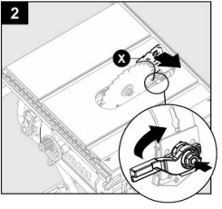
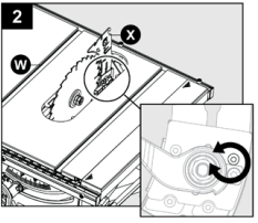
To place riving knife in raised position (for through cuts):
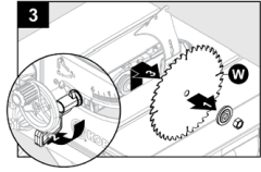
1. Raise blade (W) all the way to highest position by turning height adjusting wheel (P) clockwise.

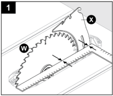
2. Lift lever up and toward the rear of the saw. Push in on the nut to release riving knife for adjustment.
ANTI-KICKBACK PAWLS INSTALLATION
- Anti-kickback pawls should only be installed for through cuts.
- Replace dull or damaged anti-kickback pawls. Dull or damaged anti-kickback pawls may not stop a kickback, increasing the risk of serious personal injury.
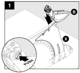
1. Unplug saw. Raise blade (W) by turning height adjusting wheel (P) clockwise. Place riving knife (X) in raised position. Press and hold button on right side of anti-kickback pawls (B). Align slot in anti-kickback pawls (B) over center slot of riving knife (X).
2. Push anti-kickback pawls (B) down until it snaps into place and release button.
Note: Pull up on anti-kickback pawl assembly to make sure it is secured to riving knife.
BLADE GUARD INSTALLATION
To install blade guard:
1. With front of blade guard (A) raised, hook back end of guard onto rear slot of riving knife (X).

2. Push front down until it is parallel to table. Lock blade guard (A) in place by pushing lever down.

3. If blade guard (A) is not parallel to table, riving knife (X) is not in raised (through cut) position. Raise and lower each side of the blade guard to verify free movement of the guard system. Be sure the guard system can be raised enough to clear your workpiece.
Note: Blade alignment with riving knife can be adjusted. See: Checking and Aligning Riving Knife and Saw Blade, page 41. Check the blade guard (A) for clearances and free movement.

FOLDING LEG STAND
1. To fold stand for moving, return side and rear extension tables to inner position. Stow rip fence and miter gauge. Grasping handles, push the stand release pedal with your foot and tilt up and forward until the saw rests on the wheels and stand feet.
STORAGE FEATURES
- The table saw has two convenient storage areas (one on either side of saw cabinet) specifically designed for storage.
- When not in use, store rip fence, blade wrenches, miter gauge, push stick and blades by securely snapping each in place.

2. Table saw can be moved to proper storage area.
BEFORE OPERATING
OPERATING COMPONENTS
- The upper portion of the blade (W) projects up through the table (V) and is surrounded by an insert called the throat plate (Y). The height of the blade (W) is set with a height adjust wheel (P) on the bevel adjustment assembly. Detailed instructions are provided in this manual for the basic cuts: cross cuts, miter cuts, bevel cuts, and compound cuts.
- The rip fence (T) is used to position work for lengthwise cuts. A scale on the front rail shows the distance between the rip fence (T) and the blade (W).
- It is very important to use the blade guard assembly for all through-cut sawing operations. The blade guard assembly includes: riving knife (X), anti-kickback pawls (B), and blade guard (A).
Turning The Saw ON and OFF
The ON/OFF paddle switch is located on the left side of the front panel of the saw.
Press the green "ON" button. Press the switch down turn the saw off.
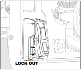
When not in use, the saw should be turned off and the power switch locked out to prevent unauthorized use. To lock out power switch, use standard long shackle lock, with a shackle post no larger than 9/32-inch (7mm) thick.
BLADES
- Your saw comes equipped with a 10 in. combination blade suitable for ripping and cross-cutting. Additional blade styles are available for specific operations such as ripping. Your local dealer can provide you with complete information.
- Kerf width must be within the limits stamped on the riving knife (X).
- Only use 10 in. blades designed for wood cutting.
Changing Blade Depth
Blade depth should be set so that outer points of blade (W) are higher than workpiece by approximately 1/8 in. to 1/4 in. and bottom of gullets are below top surface of workpiece.
- Make sure release lever (O) is locked (in down position).
- Raise blade (W) by turning height adjusting wheel (P) clockwise. Lower blade (W) by turning height/bev

Changing Blade Angle (Bevel)
Note: A 90° cut has a 0° bevel and a 45° cut has a 45° bevel.
Note: If bevel indicator is not at zero when saw blade is at 0°, see Adjusting Bevel Indicator, page 46.
- Loosen bevel control by pulling release lever (O) all the way to the right.
- Adjust bevel angle by first pushing height adjusting wheel assembly all the way to the left, maximum 45°.
- Holding knob/wheel, slide bevel indicator to the right to increase angle of blade (W) (bringing it closer to 45° from the tabletop). Holding knob/wheel, slide bevel indicator to the left to decreases the angle (bringing blade closer to 90° from the tabletop).
- Make sure blade (W) is at desired angle. To lock tighten bevel control by pushing release lever (O) to the left.

RIP FENCE
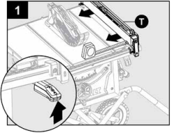
To reduce the risk of injury, always make sure the rip fence (T) is parallel to the blade (W) before beginning any operation. Using Rip Fence
- Make sure both the front and rear side of fence 10 in away from the blade.
- If not accuracy, use the 4 mm hex wrench to loose the screws for both front & rear tabs.
- Adjust the fence to proper position and make sure the fence parallel to the blade, then tighten the screws for tabs.
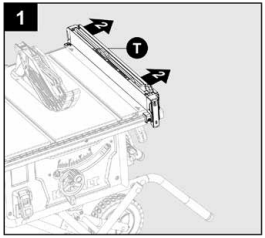
- Place the fence on the silver tabs (read the silver scale, the pointer indicates 10 in).
- For Black tabs (right 0 in ~ 10 in) and Yellow tabs (left 0 in ~ 17 in), repeat the same adjustment as above.
For thin materials use the fence on the left of the blade. Fold down the thin fence to allow use of blade guard. Subtract 2 inches from the scale for accurate measurement.

MITER GAUGE
The miter gauge provides accuracy in angled cuts. For very close tolerances, test cuts are recommended.
There are two miter gauge grooves, one on either side of blade, maximum 30° on both left or right side. . When making a 90° cross cut, use either miter gauge groove. When making a beveled cross cut (blade tilted in relation to table (V), miter gauge should be located in groove on right so that blade is tilted away from miter gauge and hands.
Using Miter Gauge
1. Loosen lock knob. With miter gauge in miter gauge groove, rotate gauge until desired angle on scale is reached. To lock retighten lock knob.

SLIDING TABLE EXTENSION
Adjust the length of the saw table (V) by using the table extension (E). Release the table by pulling side extension lock outward.
- For rip cuts between 0 in. to 20 in., set rip fence (T) on black tabs. Use the black scale for cuts with the fence in this position.
- For rip cuts between 10 to 30 inches place the fence on the silver tabs.
- For rip cuts left 0 in. to 17 in. of the blade place the fence on the yellow tabs.

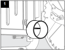
Dust Collector
1. Connect a shop vacuum or dust collection hose to dust port on back of saw for best dust collection.
CUTTING AIDS
Cutting aids such as push sticks, push blocks, featherboards and jigs should be used where appropriate to maximize your ability to control your workpiece for a safe and precise cut. When making non-through cuts or ripping narrow stock, always use a push stick, push block, featherboard and/or jig set-up so hands do not come within 6 inches of saw blade (W).
A push stick is included with your saw. Additional push sticks and other cutting aids can be purchased separately at any authorized dealer. Instructions for making cutting aids can be found at on pages 32-34.
Push Sticks
Push blocks can be purchased or made to securely hold down the workpiece against the table when making non-through cuts. They should include a gripping surface on the bottom and a handle to hold the block. Any screws running through the underside of the block to fasten the handle should be recessed in order to avoid contact with the workpiece
Push Blocks
Push blocks are blocks used to securely hold down the workpiece against the table. They include some gripping surface or handle to hold the block. Any screws running through the underside of the block to fasten the handle should be recessed in order to avoid contact with the workpiece.
Featherboards
A featherboard is a device used to help control the workpiece by guiding it securely against the table (V) or rip fence (T). Featherboards are especially useful when ripping small workpieces and for completing non-through cuts. The end is angled with a series of narrow slots to give a friction hold on the workpiece. It is locked in place on the table (V) with a C-clamp.
When using featherboard, it must be mounted in front of the saw blade and used only against the uncut portion of the workpiece to avoid a kickback that could result in serious injury.
Jigs
Jigs may be created with a variety of special set-ups to control particular workpiece shapes for particular cuts. Guidance on how to make specialized jigs can be found in woodworking magazines and other reference sources.
Do not attempt to create a jig unless you are thoroughly familiar with table saw safety. Do not use any jig that could result in pinching of a kerf or jamming of the workpiece between the jig and the blade. Incorrect setups may cause kickback which could result in serious injury.
HOW TO MAKE A PUSH STICK
- In order to operate your table saw safely, you must use a push stick whenever the size or shape of the workpiece would otherwise cause your hands to be within 6 in. (152 mm) of the saw blade or other cutter. A push stick is included with this saw.
- No special wood is needed to make additional push-sticks as long as it’s sturdy and long enough. A length of 15.7 in. (400 mm) is recommended with a notch that fits against the edge of the workpiece to prevent slipping. It’s a good idea to have several push sticks of the same length [15.7 in. (400 mm)] with different size notches for different workpiece thicknesses.
- The shape can vary to suit your own needs as long as it performs its intended function of keeping your hands away from the blade.

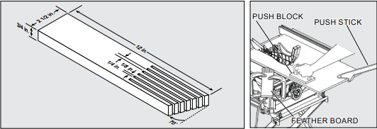
HOW TO MAKE A FEATHERBOARD
- Clamping a featherboard in front of the blade can increase safety during non-through cuts, like grooving and rabbeting, and through cuts.
- Select a solid piece of lumber approximately 3/4 in. thick, 2-1/2 in. wide and 12 in. long.
- Mark the center width on one end of stock. Miter width to 70° (see miter cut section for information on miter cuts).
- Set rip fence to allow approximately a 1/4 in. “finger” to be cut in the stock.
- Feed stock only to mark previously made at 6 in.
- Turn saw off and allow blade to completely stop rotating before removing stock.
- Reset rip fence (T) and cut spaced rips into workpiece to allow approximately 1/4 in. fingers and 1/8 in. spaces between fingers.
HOW TO MAKE A PUSH BLOCK
- Select a piece of wood about 4 in. wide, 6 in. long and 1 to 2 in. thick (a cutoff from a 2 by 4 makes a good blank for a push block).
- Drill a hole in the block and glue in a dowel to use as a handle (you can angle the hole to provide a more comfortable grip on the handle).
- To finish off the block, glue a piece of sandpaper or some kind of rubber material (old mouse pads work well) to the bottom of the block.

HOW TO MAKE AN AUXILIARY FENCE
An auxiliary fence is a device used to close the gap between rip fence and saw table. ALWAYS use an auxiliary fence when ripping material 1/8 in. or thinner to prevent stock from slipping under fence.
- Select a piece of wood 3/4 in. thick, 2 3/8 in. wide and the length of the rip fence (22 in.).
- Drill a 1/4 in. hole, 1 in. from each end and 1-1/8 in. from bottom of rip fence.
- Drill a 1/4 in. hole in the middle rip fence 1/2 in. from bottom of auxiliary fence.
- Attach auxiliary fence to rip fence; place wood against rip fence and firmly on the saw table.
- From back side of rip fence, secure wood to fence using 1-3/4 in. wood screws.
Note: Make sure hardware does not protrude from front of auxiliary wood fence.

OPERATING INSTRUCTIONS
THROUGH CUTS WITH SINGLE BLADES
CUTTING TIPS
- Knock out loose knots before making cut.
- Always provide proper support for wood as it comes out of saw.
MAKING CUTS
- Stand slightly to the side of blade path to reduce the chance of injury should kickback occur.
- Use miter gauge (U) when making cross, miter, bevel, and compound miter cuts. To secure angle, lock miter gauge (U) in place by twisting lock knob clockwise. ALWAYS tighten lock knob securely in place before use.
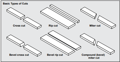
Note: All other cuts are combinations of these basic six. Operating procedures for making each kind of cut are given later in this section.
Making a Cross Cut
Cross cutting: Cross cutting is performed predominantly in a perpendicular direction with the grain of the wood.
- Make sure blade is parallel to miter gauge slot prior to cutting. Instructions for adjustment on page 44.
- Remove rip fence (T).
- Set blade (W) to correct depth for workpiece.
- Set miter gauge (U) to 0° and tighten lock knob.
- Make sure wood is clear of blade (W) before turning on saw.
- To turn saw on, lift switch button.
- Let blade (W) build up to full speed before moving workpiece into blade (W).
- Hand closest to blade (W) should be placed on miter gauge (U) lock knob and hand farthest from blade (W) should be placed on workpiece. Feed workpiece into blade (W).
- When cut is complete, turn saw off. Wait for blade (W) to come to a complete stop before removing workpiece.
Making a Rip Cut
Rip cutting: Rip cutting is performed predominantly in a parallel direction with the grain of the wood.
- Make sure blade is parallel to miter gauge slot prior to cutting. Instructions for adjustment on page 44.
- Set blade (W) to correct depth for workpiece.
- Position rip fence (T) at desired distance from blade (W) for cut and lock both ends securely.
- Make sure wood is clear of blade (W) before turning on saw.
- When ripping a long workpiece, place support same height as table (V) surface behind saw for cut work.
- Turn saw on.
- Position workpiece flat on table (V) with edge flush against rip fence (T). Let blade (W) build up to full speed before feeding workpiece into blade.
- Once blade (W) has made contact with workpiece, use hand closest to rip fence (T) for guidance. Make sure edge of workpiece remains in solid contact with both rip fence (T) and surface of table (V). If ripping a narrow piece, use push stick (D) and/or push blocks to move piece through cut and past blade.
- When cut is complete, turn saw off. Wait for blade (W) to come to a complete stop before removing workpiece.
Making a Miter Cut
- Remove rip fence (T).
- Set blade (W) to correct depth for workpiece.
- Set miter gauge (U) to 0° and tighten lock knob.
- Make sure the wood is clear of the blade (W) before turning on the saw.
- Turn the saw on.
- Let the blade (W) build up to full speed before moving the workpiece into the blade (W).
- Hand closest to blade (W) should be placed on miter gauge (U) lock knob and hand farthest from blade (W) should be placed on workpiece. Feed workpiece into blade (W).
- When cut is complete, turn saw off. Wait for blade (W) to come to a complete stop before removing workpiece.
Making a Bevel Cross Cut
- Remove rip fence (T).
- Unlock bevel locking lever.
- Adjust bevel angle to desired setting.
- Lock bevel locking lever.
- Set blade (W) to correct depth for workpiece.
- Set miter gauge (U) to 0° and tighten lock knob.
- Make sure wood is clear of blade (W) before turning on saw.
- Turn saw on.
- Let blade (W) build up to full speed before moving workpiece into blade (W).
- Hand closest to blade (W) should be placed on miter gauge (U) lock knob and hand farthest from blade (W) should be placed on workpiece. Feed workpiece into blade (W).
- When cut is complete, turn saw off. Wait for blade (W) to come to a complete stop before removing workpiece.
Making a Bevel Rip Cut
- Remove miter gauge (U).
- Unlock bevel locking lever.
- Adjust bevel angle to desired setting.
- Lock bevel locking lever.
- Set blade (W) to correct depth for workpiece.
- Position rip fence (T) at desired distance from blade (W) for cut and securely lock handle.
- Make sure wood is clear of blade before turning on saw.
- When ripping a long workpiece, place support same height as table (V) surface behind saw for cut work.
- Turn saw on.
- Position workpiece flat on table (V) with edge flush against rip fence (T). Let blade build up to full speed before feeding workpiece into blade.
- Once blade has made contact with workpiece, use hand closest to rip fence for guidance. Make sure edge of workpiece remains in solid contact with both rip fence and surface of table (V). If ripping a narrow piece, use push stick (D) to move piece through cut and past blade.
- When cut is complete, turn the saw off. Wait for the blade to come to a complete stop before removing the workpiece.
Making a Compound (Bevel) Miter Cut
- Remove rip fence (T).
- Unlock bevel locking lever.
- Adjust bevel angle to desired setting.
- Lock bevel locking lever.
- Set blade (W) to correct depth for workpiece.
- Set miter gauge (U) to desired angle and tighten adjusting clamp knob.
- Make sure wood is clear of blade (W) before turning on saw.
- Turn saw on.
- Let blade (W) build up to full speed before moving workpiece into blade (W).
- Hand closest to blade should be placed on miter gauge lock knob and hand farthest from blade (W) should be placed on workpiece.
- When cut is complete, turn saw off. Wait for blade (W) to come to a complete stop before removing workpiece.
Making a Large Panel Cut
- Place a support the same height as top of saw table (V) behind saw for cut work. Add supports to sides as needed.
- Depending on shape of panel, use rip fence (T) or miter gauge (U). If panel is too large to use either rip fence (T) or miter gauge (U), it is too large for this saw.
- Make sure wood does not touch blade (W) before saw is turned on.
- Turn saw on.
- Position workpiece flat on table (V) with edge flush against rip fence. Let blade build up to full speed before feeding workpiece into blade (W).
- Use push stick (D) to move piece through cut and past blade (W).
- When cut is complete, turn saw off. Wait for blade (W) to come to a complete stop before removing workpiece.
DADOS AND OTHER NON-THROUGH CUTS
The use of a non-through cut is essential to cutting grooves, rabbets and dados. Non-through cuts can be made using a standard blade having a diameter of 10 inches or less, or a dado blade up to 1/2 inches wide with a diameter of 8 inches or less. Non-through cuts are the only type of cuts that should be made without the blade guard assembly installed. Make sure the blade guard assembly is reinstalled upon completion of this type of cut.
Making a Non-Through Cut
- To reduce the risk of serious injury when making non-through cuts, follow all applicable warnings and instructions listed below in addition to those listed above for the relevant through cut.
- When making a non-through cut, blade (W) is covered by workpiece during most of cut. Be alert to exposed blade (W) at start and finish of every cut to avoid the risk of personal injury.
- Never feed wood with hands when making any non-through cuts such as rabbets or dados. To avoid personal injury, always use push blocks, push sticks, and/or featherboards.
- Read the appropriate section which describes the type of cut in addition to this section on non through or dado cuts. For example, if your non-through cut is a straight cross cut, read and understand the section on straight cross cuts before proceeding.
- Once all dado and non-through cuts are completed, unplug saw and reinstall riving knife (X) in raised position. Install anti-kickback pawls (B) and blade guard (A).
- Always use push blocks and or push sticks, and/or featherboards when making dado cuts to avoid the risk of serious injury.
- Unplug saw.
- Unlock release lever (O).
- Adjust bevel angle to 0°.
- Lock release lever (O).
- Remove blade guard (A) and anti-kickback pawls (B).
- Place riving knife (X) in “lowered” position.
- Set blade (W) to correct depth for workpiece.
- Depending on shape and size of wood, use either rip fence (T) or miter gauge (U).
- Plug saw into power source and turn saw on.
- Let blade (W) build up to full speed before moving workpiece into blade (W).
- Always use push blocks, push sticks, and/or featherboards when making non-through cuts to reduce the risk of serious injury.
- When cut is made, turn saw off. Wait for blade (W) to come to a complete stop before removing workpiece.
- When cut is complete re-adjust riving knife to position as detailed on page 21.
Making a Dado Cut
Dado blades are stacked blades that can be used when making through cut slots in a workpiece, or the non-through cuts described above. Dado blades require a special throat plate. Dado blades and throat plates are all sold separately
ADJUSTMENTS
The table saw has been adjusted at the factory for making very accurate cuts. However, some components might have been jarred out of alignment during shipping. Also, over a period of time, readjustment will probably become necessary due to wear.
Carefully check alignment with a framing square before beginning adjustments to confirm whether they are necessary. Use test cuts after completing adjustments to avoid damaging workpiece.
To place riving knife in lowered position (for non-through cuts):
Note: Remove throat plate (Y).
1. Raise the blade (W) by turning the height adjusting wheel (P) clockwise.

2. Lift lever up and toward rear of saw. Push in on the nut to release the riving knife for adjustment. Reinstall throat plate.

CHECKING AND ALIGNING RIVING KNIFE AND SAW BLADE
See Assembly Instructions, page 21.
REPLACING BLADE
Note: Turn power off and unplug saw. Set bevel setting to "0". Remove blade guard (A), anti-kickback pawls (B) and throat plate (Y). Raise saw blade (W).
Note: The table saw spindle shall have a normal rotation that is clockwise when viewed from the left of the position normally assumed by the operator.
1. Make sure release lever (O) is locked. Insert open end wrench (G) onto flats on arbor shaft. Insert closed end wrench (F) over blade nut.
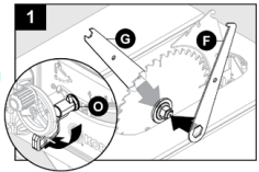
2. Holding both wrenches firmly, pull closed end wrench (F) forward while pushing open end wrench (G) to back of saw.

3. Remove nut, washer and blade (W).
4. Place new blade on arbor shaft (teeth must point down toward front of saw to work properly).
5. Place blade washer and blade nut over arbor shaft. Be sure dome side of blade washer faces out from blade and all items are snug against arbor housing. Make sure blade nut is securely tightened. DO NOT over tighten.
6. Rotate blade by hand to make sure it turns freely.
7. Lower saw blade and reinstall throat plate (Y).
Note: To replace blade (W) with an accessory blade, follow instructions provided with accessory.
RIVING KNIFE AND SAW BLADE ALIGNMENT
Blade and riving knife alignment is set at factory and in most cases will not need to be adjusted. However, the alignment should always be checked after installing blade or riving knife, and can be adjusted if necessary. If riving knife (X) is out of alignment with blade (W), adjustment is needed. Riving knife (X) must be in alignment front to back (horizontally) and top to bottom (vertically).
Note: Unplug saw. With bevel adjustment assembly in vertical (0 degree) position, raise blade (W) by turning height/bevel adjusting wheel (P) clockwise. Remove anti-kickback pawls (B) and blade guard (A).
To check/adjust (horizontally):
1. Place framing square (or straight edge) against both blade (W) and riving knife (X). Blade (W) and riving knife (X) are aligned if framing square contacts both blade (W) and riving knife (X) evenly with no gaps. Note: Place framing square between carbide teeth and measure from blade. This step will ensure framing square is square against blade from front to back of blade.
2. If blade and riving knife are not aligned, using hex head wrench, slowly turn top two set screws (located below and to either side of riving knife lock knob) until the riving knife (X) is aligned with the blade (W).
To check/adjust (vertically):
1. Place framing square on table and against both blade (W) and riving knife (X). Blade (W) and riving knife (X) are aligned if framing square contacts both blade (W) and riving knife (X) evenly with no gaps.

2. If blade and riving knife are not aligned, using hex head wrench, slowly turn the bottom set screw (located below riving knife lock knob) until the riving knife (X) is aligned with the blade (W).

CARE AND MAINTENANCE
When servicing, use only identical replacement parts. Use of any other parts may create a risk of personal injury or cause product damage.
Before performing any maintenance, make sure the tool is unplugged from the power supply and the switch is in the off position.
DO NOT at any time let brake fluids, gasoline, petroleum-based products, penetrating oils, etc., come in contact with plastic parts. Chemicals can damage, weaken, or destroy plastic.
GENERAL MAINTENANCE
- For best performance use a shop vacuum or blower to keep saw blade area, the dust collection system, the guarding system and rails free of saw dust and other debris.
- Avoid using solvents when cleaning plastic parts. Most plastics are susceptible to damage from various types of commercial solvents and may be damaged by their use. Use clean cloths to remove dirt, dust, oil, grease, etc.
- Periodically check all clamps, nuts, bolts, and screws for tightness and condition. Make sure the throat plate is in good condition and level with the table.
- Check the blade guard assembly after performing maintenance to make sure it is installed correctly and functioning properly.
- Clean plastic parts only with a soft damp cloth. DO NOT use any aerosol or petroleum solvents.
LUBRICATION
- All of the bearings in this tool are lubricated with a sufficient amount of high grade lubricant for the life of the unit under normal operating conditions. Therefore, no further lubrication is required.
TROUBLESHOOTING
Excess vibration.
1. Blade is out of balance.
1. Replace blade.
2. Blade is damaged.
2. Replace blade.
3. Legs are not properly attached to saw.
3. Tighten all hardware.
4. Work surface is uneven.
4. Reposition on flat surface. Adjust legs of leg stand.
5. Blade is warped.
5. Check saw blade installation. Replace blade if necessary.
Rip fence does not move smoothly.
1. Rip fence not mounted correctly.
1. Remount the rip fence.
2. Rails are dirty or sticky.
2. Clean and wax rails.
Cutting binds or burns work
1. Blade is dull.
1. Replace or sharpen blade.
2. Work is fed too fast.
2. Slow the feed rate.
3. Wood is warped.
3. Replace the wood.
4. Rip fence is misaligned.
4. Check and adjust the rip fence. Align the rip fence.
5. Riving knife is out of alignment.
5. See Checking and Aligning Riving Knife and Saw Blade, page 41.
Wood edges away from rip fence when ripping.
1. Blade not properly sharpened or set.
1. Re-sharpen or replace dull blade.
Saw does not make accurate 90º or 45º cuts.
1. Positive stops inside cabinet need adjusting (Bevel Cuts).
1. Adjust positive stops.
2. Miter gauge is misaligned (Miter Cuts).
2. Adjust the miter gauge.
Height adjust wheel is hard to turn.
1. Gears or screw post inside cabinet are clogged with saw dust.
1. Clean the gears.
Saw does not start.
1. Power cord or wall cord is not plugged in.
1. Plug in power cord or wall cord.
2. Circuit fuse is blown. Circuit breaker is tripped.
2. Replace circuit fuse. Reset circuit breaker.
3. Cord or switch is damaged.
3. Have the cord or switch replaced at your nearest authorized service center.
Blade makes poor cuts.
1. Blade is dull or dirty.
1. Clean, sharpen, or replace blade.
2. Blade is wrong type for cut being made.
2. Replace with correct type.
3. Blade is mounted backwards.
3. Remount blade.
Motor labors in rip cut.
1. Blade not proper for rip cut.
1. Change blade; rip blade typically has fewer teeth.