User Manual
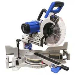
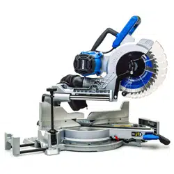
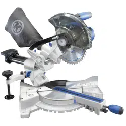
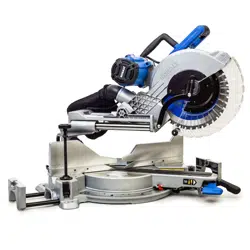
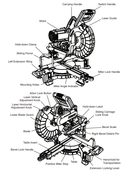
KNOW YOUR MITER SAW
ASSEMBLY INSTRUCTIONS
WARNING
To avoid injury, do not connect this miter saw to a power source until it is completely assembled and adjusted and you have read and understood the operator's manual.
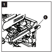
UNLOCKING THE SLIDE CARRIAGE (FIG. 1)
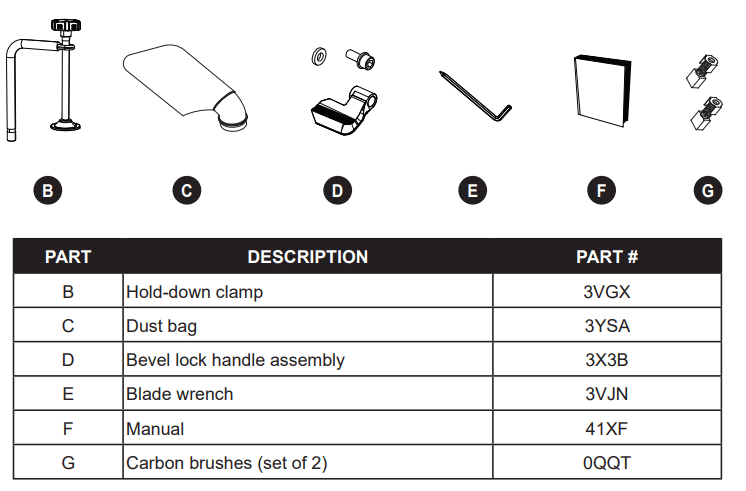
After removing the saw from the carton, loosen the slide carriage lock knob (1). When transporting or storing the miter saw, the slide carriage should always be locked in position. The slide carriage lock knob (1) is located on the right side of the slide carriage.
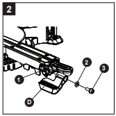
INSTALLING THE BEVEL LOCK HANDLE (FIG. 2)
Insert the bevel lock handle (D) into the hole (1) located at the front of the miter saw (A) and secure in place with the washer (2) and hex bolt (3) as shown in Fig. 2.
BLADE WRENCH (FIG. 3)
For convenient storage and prevention of loss, ther is a holder in the rear of the right side fence for storing the blade wrench (E) when not in use. Place the provided wrench in this location.

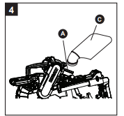
INSTALLING THE DUST BAG (FIG. 4)
- Install the dust bag (C) onto the exhaust port on the miter saw (A). Fit the connecting tube of dust bag and the exhaust port together. The dust bag assembly should be angled toward the side of the saw (as shown in Fig. 4) for best results. This will also avoid any interference during the saw operation.
NOTE: To empty the dust bag, pull out the dust bag from exhaust port. Open zipper on underside of bag and empty into waste container.
IMPORTANT: Check frequently and empty bag before it gets full.
WARNING
Do not use this saw to cut and/or sand metals. The hot chips or sparks may ignite sawdust from the bag material.
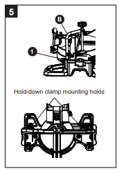
INSTALLING THE HOLD-DOWN CLAMP (FIG. 5)
NOTE: There are two mounting holes for the hold-down clamp. These are located just behind the fence on the left and right side of the base.
- Loosen the lock knob (1) behind the fence.
- Place the hold-down clamp assembly (B) in the desired mounting holes.
- Tighten the lock knob (1).
NOTE: Place the clamp on the opposite side of the base when bevelling. Always make dry runs (unpowered) before finish cuts to check the path of the blade. Ensure the clamp does not interfere with the action of the saw or guards.
ADJUSTMENT INSTRUCTIONS
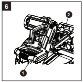
UNLOCKING AND LOCKING THE CUTTING HEAD (FIG. 6)
Unlocking the cutting head:
- To raise the cutter head from its storage/ transport position, push down slightly on the switch handle (1).
- Pull out the hold-down latch (2).
- Allow the cutting head to rise to the up position.
Locking the cutting head:
When transporting or storing the miter saw, the cutting head should always be locked in the down position.
- Push the cutting head down to its lowest position.
- Push the hold-down latch (2) into the locking hole.
CAUTION
To avoid injury and damage to the saw, transport and store the miter saw with the cutting head locked in the down position. Never use the stop latch to hold the cutting head in a down position for cutting operations.
IMPORTANT: To avoid damage, never carry the miter saw by the switch handle, the cutting arm or the miter table handle. ALWAYS use the hand holds for transportation.
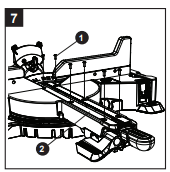
REMOVING AND INSTALLING THE TABLE INSERTS (FIG. 7)
NOTE: The miter saw comes with the table insert already installed. These instructions are for replacing or adjusting the insert.
To avoid injury:
- Always unplug the saw to avoid accidental starting. Remove all small pieces of material from the table cavity before performing any cuts, The table insert may be removed for this purpose, but always reattach the table insert prior to performing a cutting operation.
- Do not start the sliding compound miter saw without checking for interference between the blade and table insert. Damage could result to the blade, table insert or turntable if a blade strike occurs during the cutting operation.
- To remove, loosen and remove the six screws (1) on the table insert (2) with a Phillips screwdriver and remove the inserts.
- To install, reposition the left and right side inserts on either side of the cut line, replace the six screws and tighten.
- Check for blade clearance by moving the slide carriage through the full motion of the blade in the table slot. If neither side of the insert hits the saw blade, loosen the three screws for that side and adjust. Tighten the screws and check again for blade clearance.
MOUNTING THE MITER SAW (FIG. 8, 9, 10)
WARNING
To avoid injury from unexpected saw movement:
- Disconnect the power cord from the outlet and lock the cutting head in the lower position using the hold-down latch.
- Lock the slide carriage in place by tightening the slide carriage lock knob.
- To avoid back injury, lift the saw by using the designated carrying handles located on the top of the machine. Bend with your knees, not your back.
- Never carry the miter saw by the power cord or by the switch handle. Carrying the tool by the power cord could cause damage to the insulation or the wire connections resulting in electric shock or fire.
- To avoid injury from flying debris, do not allow visitors to stand near the saw during any cutting operations.
Mounting instructions:
- For stationary use, place the saw in the desired location, directly on a workbench where there is room for handling and proper support of the workpiece. The base of the saw has eight mounting holes (10-Fig. 8), four 3/8 in. holes for mounting the saw to the work surface. Bolt the base of the miter saw (1) to the work surface (5), using the recommended fastening method as shown in Fig. 9.
NOTE: Mounting hardware is not included with this tool. Bolts, nuts, washers and screws must be purchased separately.
- For portable use, place the saw on a 3/4 in. thick piece of plywood. Bolt the base of the miter saw securely to the plywood using the 11 mounting holes (10-Fig. 8) on the base. Use C-clamps to clamp this mounting board to a stable work surface at the worksite (Fig. 10).
NOTE: If a miter saw stand is used, please follow all instructions shown in that product's instructions for proper mounting.

REMOVING AND INSTALLING THE BLADE
WARNING
- Use only a saw blade diameter in accordance with the markings on the saw.
- Only use a 10 in. diameter blade with a 5/8 in. arbor hole and an operating speed of more than 4,450 RPM. Do not use blades with deep gullets. These can deflect and contact the guard, causing damage to the machine and/or serious injury.
- To avoid injury from an accidental start, make sure the switch is in the OFF position and the plug is not connected to the power source outlet.
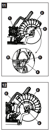
REMOVING THE BLADE (FIG. 11, 12, 13, 14, 15)
- Unplug the saw from the outlet.
- Raise the cutting head (1) to its upright position as shown in Fig 11. Raise the lower blade guard (2) to the up position shown in Fig. 11.
- Loosen the cover plate screw (3) through the hole by using the phillips head end of the provided blade wrench (D). Only loosen it enough to position past the tab (4).
NOTE: Do not remove this screw.
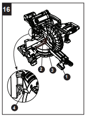
- Rotate the lower blade guard (2) back to its down position about half way. The cover plate screw (3) should stop the guard from moving any further and move the cover plate (5) upward to expose the arbor bolt (6).
- Place the hex end of the provided blade wrench (D) on the arbor bolt (6).
- Locate the arbor lock button (7) on the right side of saw, below the belt cover.
- Press the arbor lock button (7), holding it in firmly while turning the blade wrench clockwise.
- The arbor lock will engage after turning the wrench, stopping the rotation of the blade.
- Continue to hold the arbor lock button (7) to keep it engaged while turning the wrench clockwise to loosen the arbor bolt.
- Remove the arbor bolt (6), the blade collar (8) and the blade (10), as shown in Fig 15. Do not remove the inner blade collar (9).
NOTE: Pay attention to the pieces removed, noting their position and direction they face. Wipe the blade collar clean of any sawdust before installing a new blade.
INSTALLING THE BLADE (FIG. 11, 12, 13, 14, 15)
Unplug the miter saw before changing/installing the blade.
- Install a 10 in. blade with a 5/8 in. arbor, making sure the rotation arrow on the blade matches the clockwise rotation arrow on the upper guard.
- Place the outer blade collar (8) against the blade and on the arbor. Thread the arbor bolt (6) onto the arbor in a counterclockwise direction.
IMPORTANT: Make sure the flats of the blade collars are engaged with the flats on the arbor shaft. Also, the flat side of the blade collar must be placed against the blade.
- Place the hex end of blade wrench (D) on the arbor bolt (6).
- Press the arbor lock button (7), holding it in firmly while turning the blade counterclockwise.
- When arbor lock engages, continue to press it in while turning the blade wrench counterclockwise, tightening the arbor bolt securely.
- Rotate the lower blade guard (2) to its up position. The cover plate should move to its original position. Then tighten the cover plate screw (3) through the hole with the phillips head end of provided blade wrench.
- Lower the blade guard (2) and verify that the operation of the guard does not bind or stick.
- Be sure the arbor lock is released so the blade turns freely before operating the saw.
WARNING
- To avoid injury, never use the saw without the cover plate securely in place. It keeps the arbor bolt from falling out if it accidentally loosens and helps prevent the spinning blade from coming off the saw.
- Make sure the collars are clean and properly arranged. Lower the blade into the lower table and check for any contact with the metal base or the miter
- To avoid injury from an accidental start, make sure the switch is in the OFF position and the plug is not connected to the power source outlet.
- Never cut metals or masonry products with this tool. This miter saw is designed for use on wood and wood-like products only.

BEVEL STOP ADJUSTMENT (FIG. 16, 17, 18, 19)
WARNING
To avoid injury from an accidental start, make sure the switch is in the OFF position and the plug is not connected to the power source outlet.
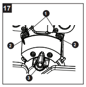
90° (0°) Bevel Adjustment (Fig. 16):
- Loosen bevel lock handle (1) and tilt the cutting arm completely to the right. Tighten the bevel lock handle (1).
- Place a combination square (2) on the miter table with the ruler against the table and the heel of the square against the saw blade.
- If the blade is not 90° square with the miter table (3), loosen the bevel lock handle (1), tilt the cutting head to the right by pulling out the right bevel detent pin (3-Fig. 17), adjust the bevel angle adjustment bolt (4) in or out with a 10 mm wrench until the blade is square with the table.
- Tilt the cutting arm back to 90°(0°) bevel and recheck for alignment.
- Repeat above steps if further adjustment is needed.
- Tighten bevel lock handle (1) when alignment is achieved.
90° Bevel Pointers Adjustment (Fig. 17):
- When the blade is exactly 90° to the table, loosen the bevel indicator screws (1) using a Phillips screwdriver.
- Adjust bevel pointers (2) to the "0" mark on the bevel scale and retighten the screw.
A WARNING
To avoid injury from an accidental start, make sure the switch is in the OFF position and the plug is not connected to the power source outlet.
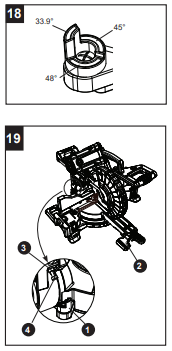
Left/Right 45° Bevel Adjustment (Fig. 18, 19):
This miter saw is equipped with a bevel detent block. for positive angles stops at 33.9°, 45° and 48°. (Fig. 18)
- Turn the left bevel detent block (1) to 45° position.
- Loosen the bevel lock handle (2) by lifting up and tilt the cutting head completely to the left.
- Using a combination square, check to see if the blade angle is 45° to the table.
- Tighten bevel lock handle (2) and jamb nut (3) when alignment is achieved.
- Adjust the 45° bevel on the other side following the same steps listed above.
- If the blade is not at 45° to the miter table, tilt the cutting arm to the right, loosen the jamb nut (3) and turn the bevel angle adjustment bolt (4) in or out with a 10 mm wrench.
- Tilt the cutting arm to the left 45° bevel and recheck for alignment.
- Repeat above until the blade is at 45° to the miter table.
Left/Right 33.9° Bevel Adjustment (Fig. 18, 19):
- Turn the left bevel detent block (1) to 33.9° position.
- Adjust the left and right side 33.9° bevel angle using the same instructions given above for adjusting the 45° bevel.
Left/Right 48° Bevel Adjustment (Fig. 18, 19):
- Turn the left bevel detent block (1) to 48° position.
- Adjust the left and right side 48° bevel angle using the same instructions given above for adjusting the 45° bevel.
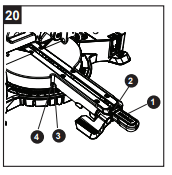
MITER SCALE (FIG. 20)
The sliding compound miter saw scale can be easily read, showing miter angles from 0° to 55° left and 0° to 60° right. The most common angle settings have positive stops at 0°,15°, 22.5°, 31.6°, 45° left and right and 60° right only. These positive stops position the blade at the desired angle quickly and accurately. Follow the instructions below for quickest and most accurate adjustments.
To Adjust Miter Angles:
- Lift up on the miter lock handle (1) to unlock the table.
- Move the table while pressing down on the positive stop lock button (2) to align the pointer (3) to the desired degree measurement.
- If the desired angle is one of the ten positive stops, press down the positive stop locking button (2), making sure it snaps into position, then secure by pressing down the miter handle (1).
- If the miter angle desired is not one of the ten positive stops, simply lock the miter table into position by pressing down on the miter lock handle (1).
Miter Angle Pointer Adjustment (Fig. 20):
- Move the table to the 0° positive stop.
- Loosen the screw (4) that holds the pointer (3) with a Phillips screwdriver.
- Adjust the pointer (3) to the 0° mark and retighten the screw (4).
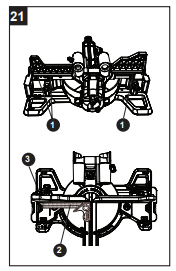
ADJUSTING FENCE SQUARENESS (Fig.21)
- Lower the cutting arm and lock in position.
- Loosen the three fence locking bolts (1) using a 5 mm wrench.
- Using a square (2), lay the heel of the square against the blade and the ruler against the fence (3) as shown.
- Adjust the fence to be 90° to the blade and tighten the three fence locking bolts (1).
- After fence has been align make a cut at 90° using a scrap of wood and check squareness on the piece. Readjust if necessary.
NOTE: If the saw has not been used recently, recheck blade squareness to the fence and readjust if needed.
WARNING: Always make dry runs (unpowered) before finish cuts to check the path of the blade and the operation of the guards. Ensure the fence does not interfere with the action of the saw or guards.
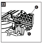
REMOVING OR INSTALLING THE SLIDING FENCE (FIG. 22)
At some extreme angles, the right or left side fence might have to be removed to ensure proper clearance prior to making the cut.
CAUTION
The side sliding fence must be removed when making any bevel angle cuts greater than 33.9° in combination with any miter angle.
- To remove the sliding fence, loosen the fence locking knob (1) by turning it counterclockwise, then slide the fence (2) out from the fence slot.
- To install the sliding fence, slide the sliding fence into the fence slot, then lock the fence by turning the fence locking knob (1) clockwise.
NOTE: This miter saw is equipped to cut wide boards up to 12 in., see section SLIDE CUTTING WIDE BOARDS
SETTING CUTTING DEPTH (FIG. 23)
The depth of cut can be preset for even and repetitive shallow cuts.
- Adjust the cutting head down until the teeth of the blade are at the desired depth.
- While holding the upper arm in that position, turn the stop knob (1) until it touches the stop plate (2).
- Recheck the blade depth by moving the cutting head front to back through the full motion of a typical cut along the control arm.
NOTE: Use a wooden spacer between the fence and the workpiece for a consistent depth through the cut. Use the hold-clamp to secure the wooden spacer and workpiece firmly before making a cut.
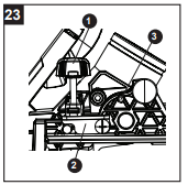
MAXIMUM CUTTING DEPTH (FIG. 23)
The maximum depth travel of the cutting head was set at the factory.
- Rotate the stop plate (2) clockwise to touch the stop rod (3).
- Recheck the blade depth by moving the cutting head front to back through the full motion of a typical cut along the control arm.
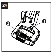
TO TURN LASER GUIDE ON (FIG. 24)
- To turn laser on, press on/off rocker switch (1) to "ON" position.
- To turn laser off, press on/off rocker switch (1) to "OFF" position.
ALIGNING THE LASER GUIDE (FIG. 24, 25)
The laser line must always be correctly aligned with the blade to ensure straight, even cutting. Your tool is equipped with a laser cutting guide that uses a Class II laser line. The laser line will enable you to preview the saw blade path on the stock to be cut before starting the miter saw. The saw must be connected to the power source and the laser on/ off switch must be turned on for the laser line to show.
When doing any laser guide adjustments, always insert a padlock or chain with padlock (not included) through the hole (2) in the trigger switch, locking the tool's switch and preventing turning the machine on. Do not remove the padlock from the ON/OFF switch until all laser adjustments are completed.

AVOID DIRECT EYE CONTACT
- A laser is radiated when the laser guide is turned on. Avoid direct eye contact.
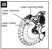
- Laser Warning Label: Laser radiation do not view directly with optical instruments class 1M laser product <0.39mW, 400-700nm, CW, Acc.IEC 60825-1.
- Laser Aperture Label. (Fig. 25)
- Laser Notice Label (Fig. 25): Complies with FDA preformance standards for laser products except for deviations pursuant to Laser Notice No. 50, dated june 24, 2007.
- NOTE: All the adjustments for the operation of this machine have been completed at the factory. Due to normal wear and use, some occasional readjustments may be necessary.
- CAUTION: Use of controls or adjustments or performance of procedures other than those specified herein may result in hazardous radiation exposure.
- CAUTION: The use of optical instruments with this product will increase eye hazard.
LASER GUIDE ADJUSTMENT (FIG. 26, 27, 28, 29)
NOTE: All the adjustments for the operation of this machine have been completed at the factory.
Due to normal wear and use, some occasional readjustments may be necessary.
WARNING
To prevent serious injury, insert a padlock (not provided) or chain with padlock through the hole in the ON/OFF Trigger Switch prior to making any laser adjustment. DO NOT remove the lock from the ON/OFF Trigger Switch during any laser adjustment.
A. Checking Laser Line Alignment (Fig. 26, 28)
- Set the saw to a 0° miter and 0° bevel setting.
- Use a combination square to mark a 90° angle running across the top and down the front of a board. This line will serve as the pattern line (Fig. 28) to adjust the laser. Place the board on the saw table.
- Carefully lower the saw head down to align the saw blade with the pattern line. Position the saw blade to the right side of the "pattern line" for the laser line location. Lock board in place with hold-down clamp.
- With the saw plugged in, turn on the laser guide. The laser line is parallel to the "pattern line."
NOTE: The laser line is calibrated and set up to project to the left of the blade.
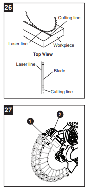
- Slide the cutting head forward enough so that the laser line is visible on the front of the board.
- Looking at the front of the board, if the laser line is not parallel to the "pattern line" please follow the instructions listed below under "Front Line" paragraph.
- Looking at the top of the board, if the laser line is not parallel to the "pattern line" please follow the instructions listed below under "Top Line" paragraph.
B. Adjusting the Position of the Laser Line (Fig. 27, 28, 29)
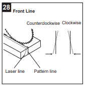
Front Line (Fig. 27, 28)
If the laser line is angled from left to right, turn the laser vertical adjustment knob (1) counterclockwise to align the laser line parallel with pattern line. If the laser line is angled from right to left, turn the knob clockwise to align the laser line parallel with pattern line.
Top Line (Fig. 27, 29)
If the laser line is angled from left to right, turn the laser horizontal adjustment knob (2) clockwise to align the laser line parallel with pattern line. If the laser line is angled from right to left, turn the knob counterclockwise to align the laser line parallel with pattern line.
After performing the above adjustments, visually check that both the front and top laser lines are parallel with pattern line.
NOTE: If you have any problem or questions concerning the laser guide, call the Customer Service Department at 1-888-356-2258.

OPERATING INSTRUCTIONS
BEFORE USING THE MITER SAW
WARNING
To avoid mistakes that could cause serious, permanent injury, do not plug the tool in until the following steps are completed:
- Completely assemble and adjust the saw, following the instructions (SEE ASSEMBLY AND ADJUSTMENTS SECTIONS).
- Learn the use and function of the ON/OFF switch, upper and lower blade guards, stop latch, bevel lock handle and cover plate screws.
- Review and understand all safety instructions and operating procedures in this Operator's Manual (SEE SAFETY & OPERATIONS SECTIONS).
- Review the MAINTENANCE and TROUBLESHOOTING for your miter saw.
- To avoid injury or possible death from electrical shock, make sure your fingers do not touch the plug's metal prongs when plugging or unplugging your miter saw (SEE ELECTRICAL REQUIREMENTS AND SAFETY SECTIONS).
BEFORE EACH USE
Inspect your saw.
- Disconnect the miter saw. To avoid injury from accidental starting, unplug the saw before making any adjustments, including setup and blade changes.
- Compare the direction of rotation arrow on the guard to the direction arrow on the blade. The blade teeth should always point downward at the front of the saw.
- Tighten the arbor bolt.
- Tighten the cover plate screw.
- Check for damaged parts, including:
- Alignment of moving parts
- Damaged blade teeth
- Damaged electric cords
- Binding of moving parts
- Broken/cracked castings: base, table, motor, upper arm
- Function of arm return spring and lower guard: Push the cutting arm all the way down and then let it rise until it stops. The lower guard should close fully. Follow the instructions in the Troubleshooting Guide for adjustment, if necessary.
- Keep all guards in place, in working order and properly adjusted. If any part of this miter saw is missing, damaged or broken, or any electrical parts do not work, turn off the saw and unplug it. Replace damaged, missing or defective parts before using the saw again.
- Maintain tools with care. Keep the miter saw clean for best and safest performance. Follow instructions for lubricating. Do not apply lubricants to the blade while it is spinning.
- Remove all adjusting wrenches from the tool before turning it on.
USE ONLY THE RECOMMENDED ACCESSORIES
- Follow the instructions that come with the accessory. The use of improper accessories may cause risk of injury to persons.
- Choose the correct 10 in. blade for the material and the type of cutting you plan to do.
- Make sure the blade is sharp, undamaged and properly aligned. With the saw unplugged, push the cutting arm all the way down. Manually spin the blade and check for clearance. Tilt the miter head to a 45° bevel and repeat the test.
- Make sure the blade and arbor collars are clean.
- Make sure all clamps and locks are tight and there is no excessive play in any parts.
KEEP YOUR WORK AREA CLEAN
Cluttered areas and benches invite accidents.
PLAN YOUR WORK
Use the right tool. Do not force a tool or attachment to do a job it was not designed to do. Use a different tool for any workpiece that cannot be held in a solidly braced, fixed position.
WARNING
This machine is NOT designed for cutting masonry, masonry products or ferrous metals (steel, iron and iron-based metals). Use this miter saw to cut only wood and wood by-products. Other materials may shatter, bind the blade or create other dangers. Remove all nails that may be in the workpiece to prevent sparking that could cause a fire.
DRESS FOR SAFETY
Any power tool can throw foreign objects into the eyes. This can result in permanent eye damage. Everyday eyeglasses have only impact resistant lenses and are not safety glasses. Glasses or goggles not in compliance with ANSI Z87.1 could seriously injure you if they break
- Do not wear loose clothing, gloves, neckties or jewelry (rings, watches). They can get caught and draw you into moving parts
- Wear non-slip footwear.
- Tie back long hair. miter saw.
- Roll long sleeves above the elbow.
- Noise levels vary widely. To avoid possible hearing damage, wear earplugs when using any
- For dusty operations, wear a dust mask along with safety goggles.
INSPECT YOUR WORKPIECE
- Make sure there are no nails or foreign objects in the part of the workpiece being cut.
- Plan your work to avoid small pieces that may bind or are too small to clamp and hold securely.
- Plan the way you will grasp the workpiece from start to finish. Avoid awkward operations and hand positions. A sudden slip could cause your fingers or hand to move into the blade.
DO NOT OVERREACH
Keep good footing and balance. Keep your face and body to one side, out of the line of a possible kickback. NEVER stand in the line of the blade.
Never cut freehand:
- Brace your workpiece firmly against the fence and table stop so it will not rock or twist during the cut.
- Make sure there is no debris between the workpiece and the table or fence. Make sure there are no gaps between the workpiece, fence and table that will let the workpiece shift after it is cut.
- Keep the cut piece free to move sideways after it is cut off. Otherwise, it could get wedged against the blade and thrown violently.
- Only the workpiece should be on the saw table.
- Secure work. Use clamps or a vise to help hold the work when it is practical.
USE EXTRA CAUTION WITH LARGE OR ODD SHAPED WORKPIECES
- Use extra supports (tables, sawhorses, blocks, etc.) for workpieces large enough to tip.
- Never use another person as a substitute for a table extension or as an additional support for a workpiece that is longer or wider than the basic miter saw table, or to help feed, support or pull the workpiece.
- Do not use this saw to cut small pieces. If the workpiece being cut would cause your hand or fingers to be within 7-1/2 in. of the saw blade, the workpiece is too small. Keep hands and fingers out of the "no-hands zone" area marked on the saw table.
- When cutting odd shaped workpieces, plan your work so it will not bind in the blade and cause possible injury. Moulding, for example, must lie flat or be held by a fixture or jig that will not let it move when cut.
- Properly support round material such as dowel rods or tubing, which have a tendency to roll when cut, causing the blade to "bite."
WHEN SAW IS RUNNING
WARNING
Do not allow familiarity from frequent use of your miter saw to result in a careless mistake. A careless fraction of a second is enough to cause severe injury.
Before cutting, if the saw makes an unfamiliar noise or vibrates, stop immediately. Turn the saw OFF. Unplug the saw. Do not restart until you find and correct the problem.
WARNING
To ensure the blade path is clear of obstructions, always make a dry run of the cut without power before making any cuts on the workpiece.
BODY AND HAND POSITION (FIG. 30)
WARNING
Never place hands near the cutting area. Proper positioning of your body and hands when operating the miter saw will make cutting easier and safer.
Keep children away. Keep all visitors at a safe distance from the miter saw. Make sure bystanders are clear of the saw and workpiece. Do not force the saw. It will do the job better and safer at its designed rate.
A WARNING
Operator and all by-standers must wear proper safety goggles that comply with OSHA/ANSI requirements Z87.1.
Starting a cut:
- Place hands at least 7-1/2 in. away from the path of the blade - out of the "no-hands zone."
- Hold workpiece firmly against the fence to prevent movement toward the blade.
- Turn the laser guide on for pre-alignment of your cut.
- With the power switch OFF, bring the saw blade down to the workpiece to see the cutting path of the blade. Raise the saw blade back up before turning the saw on.
- Squeeze trigger switch to start saw.
- Lower blade into workpiece with a firm downward motion.
- On wider boards, slide the cutting arm back toward fence to make the cut.
Finishing a cut:
- Hold the cutting arm in the down position.
- Release trigger switch and wait for all moving parts to stop before moving your hands and raising the cutting arm.
- If the blade doesn't stop within 6 seconds, unplug the saw and follow the instructions in TROUBLESHOOTING.
Before freeing jammed material:
- Release trigger switch.
- Wait for all moving parts to stop.
- Unplug the miter saw.

BASIC SAW OPERATIONS
WARNING
For your convenience, your saw has a blade brake.
The brake is not a safety device. Never rely on it to replace the proper use of the guard on your saw.
If the blade doesn't stop within approximately 6 seconds, wait for the blade to stop, unplug the saw and follow the instructions in TROUBLESHOOTING.
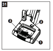
TO TURN SAW ON (FIG. 31)
This miter saw is equipped with a two step ON/OFF trigger switch. Press down on the yellow safety lock switch (2) and squeeze the trigger switch (1) to turn the miter saw ON.
NOTE: Make the ON/OFF switch childproof. Insert a padlock or chain with a padlock (not included) through the hole (3) in the trigger switch, locking the tool's switch and preventing children and other unauthorized users from turning the machine on.
The miter saw is equipped with an electric brake. When the trigger switch is released, the electric blade brake will stop the blade within 6 seconds.
WARNING
- To avoid injury, after completing a cut and releasing the trigger switch, wait and confirm the blade has stopped before raising the cutting head.
- To avoid injury, check and tighten the arbor bolt periodically.
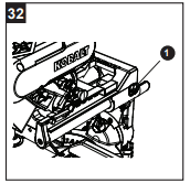
SLIDING CARRIAGE SYSTEM (FIG. 32)
CAUTION
To reduce the risk of injury, return carriage to the full rear position after each crosscut operation.
- For chop cutting operations on small workpieces, slide the cutting head assembly completely toward the rear of the unit and tighten the carriage lock knob (1).
- To cut wide boards up to 12 in., the carriage lock knob must be loosened to allow the cutting head to slide freely.
NOTE: Please refer to the section of "SLIDE CUTTING WIDE BOARDS" on page 33 to cut wide boards up to 12 in.
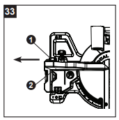
SLIDING FENCE (FIG. 33)
WARNING
The sliding fence must be extended when making any bevel cut. Failure to extend the sliding fence will not allow enough space for the blade to pass through, which could result in serious injury. At extreme miter or bevel angles, the saw blade may also contact the fence.
- Loosen the fence locking knob (1) by turning it counterclockwise, then slide the fence (2) out.
- Tighten the fence locking knob (1).
NOTE: When transporting the saw, always secure the sliding fence in the inward position and locked cut.
BEFORE LEAVING THE SAW
- Never leave tool running unattended. Turn power OFF. Wait for all moving parts to stop.
- Make workshop childproof. Lock the shop. Disconnect master switches. Store tool away from children and other unqualified users.
WARNING
To avoid injury from materials being thrown, always unplug the saw to avoid accidental starting and remove small pieces of material from the table cavity.
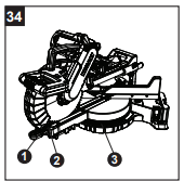
MITER CUT (FIG. 34)
- When a miter cut is required, unlock the miter table by lifting up the miter lock handle (1).
- While holding the miter handle, press down on the positive stop locking button (2).
- Rotate the miter table to the right or left with the miter handle.
- When the table is in the desired position, as shown on the miter scale (3), release the positive stop locking button and pressing down the miter handle to tighten the miter table.
- The table is now locked at the desired angle.
- Positive stops are provided at 0°, 15°, 22.5°, 31.6° 45° left and right and 60° right.
- Turn the laser guide on and position the workpiece on the table for pre-alignment of your
IMPORTANT: Always tighten the miter lock handle before performing every cutting operation.
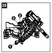
BEVEL CUT (FIG. 35)
WARNING
The sliding fence must be extended when making any bevel cut. Failure to extend the sliding fence will not allow enough space for the blade to pass through which could result in serious injury. At extreme miter or bevel angles, the saw blade may also contact the fence.
WARNING
The side sliding fence must be removed when making any bevel angle cuts greater than 33.9° in combination with any miter angle.
- When a bevel cut is required, loosen the bevel lock handle (1) by turning it clockwise.
- Tilt the cutting head to the desired angle, as shown on the bevel scale (2).
- The blade can be positioned at any angle, from a 90° straight cut (0° on the scale) to a 45° left/right bevel. Tighten the bevel lock handle (1) to lock the cutting head in position. Positive stops are provided at 0°, 33.9° and 45°.
- Turn the laser guide on and position the workpiece on the table for pre-alignment of your cut.
COMPOUND CUT (FIG. 36)
A compound cut is the combination of a miter and a bevel cut simultaneously.
- Extend the sliding fence as described in "SLIDING FENCE" section on page 31.
- Loosen the bevel lock handle (1) and position the cutting head at the desired bevel position. Lock the bevel lock handle (1).
- Loosen the miter handle (2) by lifting it up. Press down the positive stop locking button (3) and position the table at the desired miter angle. Release the positive stop locking button (3) and lock the miter handle (2) by pressing it down.
- Turn the laser guide on and position the workpiece on the table for pre-alignment of your cut.

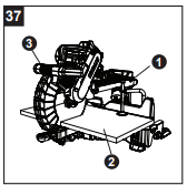
SLIDE CUTTING WIDE BOARDS (Fig. 37)
To avoid injury:
- Let the blade reach full speed before cutting. This will help reduce the risk of a thrown workpiece.
- Do not make crosscuts by lowering the blade and pulling the saw head through the wood toward you. The blade may try to climb up on top of the workpiece, causing the cutting assembly and spinning blade to kick back forcefully.
- Set both the desired bevel angle and/or the miter angle and lock into position.
- Use a hold down clamp to secure the workpiece (2).
- Unlock the carriage lock knob (1) and allow the cutting head assembly to move freely.
- Grasp the switch handle (3) and pull forward until the center of the saw blade is over the front of the workpiece (2).
- Engage the trigger to turn the saw on.
- When the saw reaches full speed, slowly push the saw handle down, cutting through the leading edge of the workpiece (2).
- Slowly move the saw handle back toward the fence, completing the cut.
- Release the trigger and allow the blade to stop spinning before raising the cutting head and removing the workpiece (2).
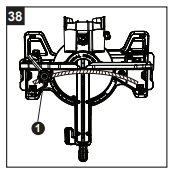
CUTTING BOWED MATERIAL (FIG. 38)
A bowed workpiece must be positioned against the fence and secured with a clamp (1) before cutting as shown. Do not position workpiece incorrectly or try to cut the workpiece without the support of the fence. This will cause the blade to bind and could result in personal injury.
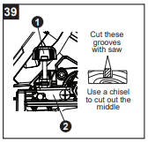
CUTTING GROOVES (FIG.39)
WARNING
DO NOT USE A DADO BLADE, use only the standard 10 in. diameter saw blade for this operation.
- Mark lines identifying the width and depth of the desired cut on the workpiece and position on the table so the outside tip of the blade is positioned on the inside edge of the line. Use a clamp to secure the workpiece beside the blade.
- Lower the cutting head to the depth marked on the workpiece, holding the upper arm and adjust the stop knob (1) until it touches the stop plate (2).
- Cut two parallel grooves as shown in Fig. 39.
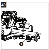
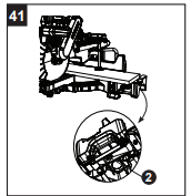
WORKPIECE SUPPORT (FIG. 40, 41)
NOTE: Long pieces need extension wing support.
Lift up the lock lever (1) to unlock the extension table. Slide the extension wing to desired position and push down the lock lever (1) to tighten. If the lock lever (1) is not tight enough, adjust the nuts (2) located underneath the base 1/4 turn counterclockwise (Fig. 41).
AUXILIARY WOOD FENCE (FIG. 42)
When making multiple or repetitive cuts that result in cut-off pieces of one inch or less, it is possible for the saw blade to catch the cut-off piece and throw it out of the saw or into the blade guard and housing, possibly causing damage or injury. To minimize this, an auxiliary wood fence can be mounted to your saw.
Holes are provided in the saw fence to attach an auxiliary wood fence. This fence is to be constructed of straight wood approximately 3/4 in. thick by 2-1/2 in. high by 18 in. long.
Attach the wood fence securely and make a full depth cut to make a blade slot. Check for interference between the wood fence and the lower blade guard. Adjust if necessary.
NOTE: This auxiliary fence is used only with the saw blade in the 0° bevel position (90° to the table). The auxiliary wood fence must be removed when bevel cutting.

CUTTING BASE MOULDING (FIG. 43)
Base mouldings and many other mouldings can be cut on a compound miter saw. The setup of the saw depends on moulding characteristics and applications, as shown. Perform practice cuts on scrap material to achieve best results:
- Always make sure mouldings rest firmly against the fence and table. Use hold-down or C-clamps, whenever possible, and place tape on the area being clamped to avoid marks.
- Reduce splintering by taping the cut area prior to making cut. Mark cut line directly on the tape.
- Splintering typically happens due to wrong blade application and thinness of the material.
NOTE: Always perform a dry run cut so you can determine if the operation being attempted is possible before power is applied to the saw.

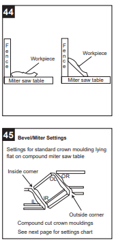
CUTTING CROWN MOULDING (FIG. 44, 45)
Your compound miter saw is suited for the difficult task of cutting crown moulding. To fit properly, crown moulding must be compound-mitered with extreme accuracy. The two surfaces on a piece of crown moulding that fit flat against the ceiling and wall are at angles that, when added together, equal exactly 90°
Most crown moulding has a top rear angle (the section that fits flat against the ceiling) of 52° and a bottom rear angle (the section that fits flat against the wall) of 38°.
In order to accurately cut crown moulding for a 90° inside or outside corner, lay the moulding with its broad back surface flat on the saw table.
When setting the bevel and miter angles for compound miters, remember the settings are interdependent; changing one changes the other, as well.
NOTE: The chart below references a compound cut for crown moulding ONLY WHEN THE ANGLE BETWEEN THE WALLS EQUALS 90°.
Bevel/Miter Settings
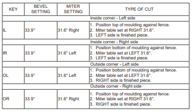
CROWN MOULDING CHART
Compound Miter Saw
Miter and Bevel Angle Settings
Wall to Crown Moulding Angle

CARE AND MAINTENANCE
WARNING
- To avoid fire or toxic reaction, never use gasoline, naphtha, acetone, lacquer thinner or similar highly volatile solvents to clean the miter saw.
- To avoid injury from unexpected starting or electrical shock, unplug the power cord before working on the saw.
- For your safety, this saw is double insulated. To avoid electrical shock, fire or injury, use only parts identical to those identified in the parts list. Reassemble exactly to avoid electrical shock.
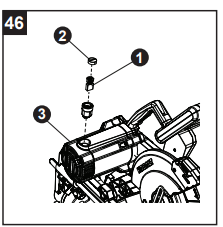
REPLACING CARBON BRUSHES (FIG. 46)
The carbon brushes (1) furnished will last approximately 50 hours of running time, or 10,000 ON/OFF cycles. Replace both carbon brushes when either has less than 1/4 in. length of carbon remaining, or if the spring or wire is damaged or burned. To inspect or replace brushes, first unplug the saw. Remove the black plastic cap (2) on the side of the motor (3). Carefully remove the spring- loaded cap. Pull out the brush and replace. Repeat for the other side. Reverse the procedure for reassembly. Press the metal part of the carbon brush into the hole where the carbon part fits. Tighten the cap snugly but do not overtighten.
NOTE: To reinstall the same brushes, first make sure the brushes go back in the way they came out. This will avoid a break-in period that reduces motor performance and increases wear.
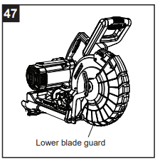
LOWER BLADE GUARD (FIG. 47)
Do not use the saw without the lower blade guard.
The lower blade guard is attached to the saw for your protection. Should the lower guard become damaged, do not use the saw until the damaged guard has been replaced. Check regularly to make sure the lower guard is working properly. Clean the lower guard of any dust or buildup with a damp cloth.
- Do not use solvents on the guard. They could make the plastic cloudy and brittle.
- When cleaning the lower guard, unplug the saw to avoid unexpected start-up.
SAWDUST
Periodically, sawdust will accumulate under the worktable and base. This could cause difficulty in the movement of the worktable when setting up a miter cut. Frequently blow out or vacuum up the sawdust.
If blowing sawdust, wear proper eye protection to keep debris from blowing into eyes.
FREE WARNING LABEL REPLACEMENT: If your warning labels become illegible or are missing, call 1-800-243-5114 for a free replacements.
WARNING
DO NOT replace the power cord. If you have any problem or questions concerning the power cord, call the Customer Service Department at 1-888-356-2258.
TROUBLESHOOTING
TROUBLESHOOTING - MOTOR
Brake does not stop the blade within 6 seconds.
1. Motor brushes not sealed or lightly sticking.
- Inspect, clean and/or replace brushes. See MAINTENANCE section.
2. Motor brake overheated from use of defective or wrong size blade or rapid ON/OFF cycling.
- Use the recommended blade. Allow to cool down.
3. Arbor bolt loosened.
4. Other.
- Contact customer service.
Motor does not start.
1. Blown fuse.
- Use and check the 20A time-delay fuse or the circuit breaker.
2. Worn brush.
3. Other.
- Contact customer service.
Excessive brush spark when the switch is released.
1. Brush worn.
TROUBLESHOOTING-SAW OPERATION
Blade hits table.
1. Misalignment.
Angle of cut not accurate. Cannot adjust miter.
1. Miter table locked.
- Push positive stop locking lever down and rotate table. See OPERATION section.
2. Sawdust under table.
- Vacuum or blow out dust. WEAR EYE PROTECTION.
Cutting arm wobbles.
1. Loose pivot points.
Cutting arm will not fully raise or blade guard will not fully close.
1. Part failure.
- Contact customer service.
2. Pivot spring not replaced properly after service.
- Contact customer service.
3. Sawdust build-up.
- See CARE AND MAINTENANCE section.
Blade binds, jams, burns wood.
1. Improper operation.
- See BASIC SAW OPERATIONS section.
2. Dull blade.
- Replace or sharpen blade.
3. Improper blade size.
- Replace with 10 in. diameter blade.
4. Warped blade.
Saw vibrates or shakes
1. Saw blade not round
2. Saw blade damaged.
3. Saw blade loose.
4. Saw blade warped.
REPLACEMENT PARTS LIST
For replacement parts, call our customer service department at 1-888-3KOBALT, 8 a.m - 8 p.m , EST, Monday - Friday