
1
MODEL #SM2518LW
10-IN COMPACT SLIDING
DUAL-BEVEL MITER SAW
Español p. 45
SC22231
Questions, problems, missing parts? Before returning to your retailer, call our
customer service department at 888-3KOBALT (888-356-2258), 8 a.m. - 8 p.m., EST,
Monday - Sunday. You could also contact us at [email protected].
Serial Number MFG Date Purchase Date
ATTACH YOUR RECEIPT HERE
KOBALT and logo design are trademarks or
registered trademarks of LF, LLC. All Rights Reserved.
ITEM #5034336

2
3URGXFW6SHFL¿FDWLRQV 2
Package Contents ............................................................................................................ 3
General Power Tool Safety Warnings ............................................................................... 6
Electrical Safety Information ............................................................................................. 11
Preparation ........................................................................................................................ 13
Assembly Instructions ....................................................................................................... 14
Adjustment Instructions ..................................................................................................... 16
Operating Instructions ....................................................................................................... 24
Crown Molding Chart ...................................................................................................... 36
Care and Maintenance ...................................................................................................... 37
Troubleshooting ................................................................................................................. 39
Replacement Parts List ..................................................................................................... 40
Warranty ............................................................................................................................ 44
MOTOR CUTTING CAPACITY
Power Source 15 A, 120 V a.c., 60 Hz Crosscut 3-1/2 in. x 12 in.
Arbor Shaft Size 5/8 in. Miter 45° Left & Right 3-1/2 in. x 8 in.
Speed (No load) 4,450 RPM Bevel 45° Left 1-5/8 in. x 12 in.
Electric Brake Yes Bevel 45° Right 1-1/4 in. x 12 in.
Double Insulated Yes 45° Miter & 45° Bevel (left) 1-5/8 in. x 8 in.
BLADE 45° Miter & 45° Bevel (right) 1-1/4 in. x 8 in.
Diameter 10 in. Crown Molding Nested 5-3/4 in.
Arbor 5/8 in. Base Molding Against Fence 4-1/2 in.
Tooth Thickness 0.1 in. Miter Range 0°-55° Left, 0°-60° Right
Bevel Range 0°-48° Left & Right
MITER/BEVEL POSITIVE STOP ANGLES
Miter Detent
Stops
0°, 15°, 22.5°, 31.6°, 45°, 55° left
0°, 15°, 22.5°, 31.6°, 45°, 60° right
Bevel Positive
Stops
0°, 45° left & right
TABLE OF CONTENTS
PRODUCT SPECIFICATIONS
3
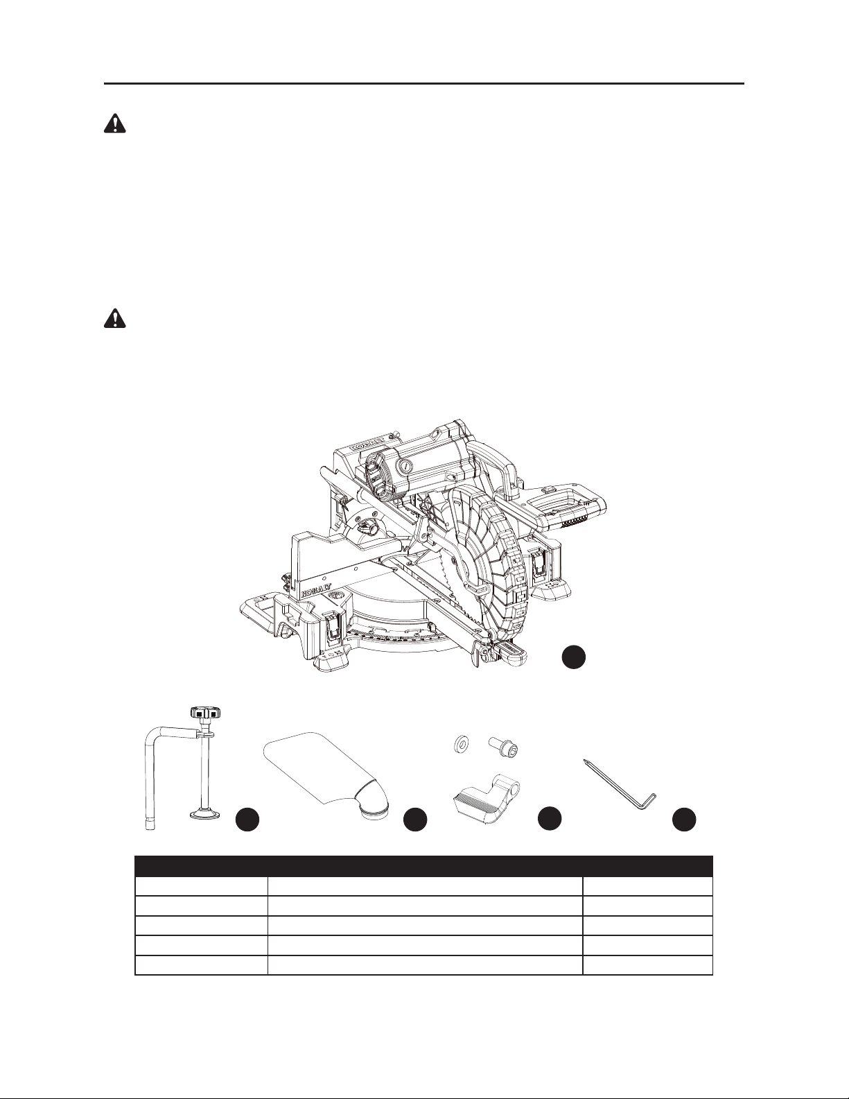
PACKAGE CONTENTS
UNPACKING YOUR MITER SAW
To avoid injury from unexpected starting or electrical shock, do not plug the power cord into a
source of power during unpacking and assembly. The cord must remain unplugged whenever you
are adjusting/assembling the saw.
1. Remove the miter saw from the carton.
IMPORTANT:
Do not lift miter saw by the trigger switch handle. It may cause misalignment. Lift
the saw by the hand holds for transportation.
2. Place the saw on a secure, stationary work surface.
3. Separate all parts from the packing material. Check each one with the illustration below to
make certain all items are accounted for before discarding any packing material.
If any part is missing or damaged, do not attempt to assemble the miter saw or plug in the power
cord until the missing or damaged part is correctly replaced. To avoid electric shock, use only
identical replacement parts when servicing double-insulated tools.
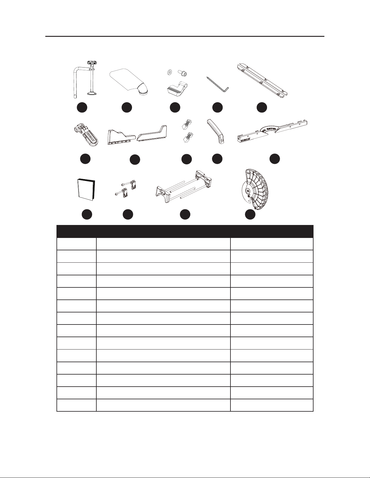
PARTS DESCRIPTION QUANTITY
A Miter saw 1
B Hold-down clamp 1
C Dust bag 1
D Bevel lock handle assembly 1
E Blade wrench 1
WARNING
WARNING
A
B C
D
E
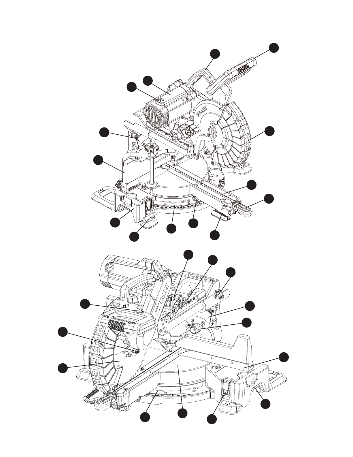
4
KNOW YOUR MITER SAW
F
G
H
I
J
T
U
W
X
Y
Z
AA
BB
CC
DD
EE
FF
V
K
L
M
N
O
P
R
Q
S

5
PARTS DESCRIPTION QUANTITY
F Switch handle 1
G Lower blade guard 1
H Table insert 2
I Miter lock handle 1
J Bevel lock handle 1
K Miter angle pointer 1
L Miter scale 1
M Mounting hole 8
N Left extension wing 1
O Sliding fence 2
P Bevel angle pointer 2
Q Carbon brush 2
R Motor 1
S Carrying handle 1
T Cutting depth stop knob 1
U Hold-down latch 1
V Sliding carriage lock knob 1
W Bevel scale 1
X Right bevel detent pin 1
Y Fence 1
Z Hand-hold for transportation 2
AA Extension locking lever 2
BB Miter table 1
CC Positive miter stop 11
DD Blade 1
EE Arbor lock button 1
FF LED ON/OFF switch 1

6
:$51,1*5HDGDOOVDIHW\ZDUQLQJVLQVWUXFWLRQVLOOXVWUDWLRQVDQGVSHFL¿FDWLRQV
provided with this power tool. Failure to follow all instructions listed below may result in electric
VKRFN¿UHDQGRUVHULRXVLQMXU\
Save all warnings and instructions for future reference.
The term "power tool" in the warnings refers to your mains-operated (corded) power tool or
battery-operated (cordless) power tool.
Work area safety
ŏ Keep work area clean and well lit. Cluttered or dark areas invite accidents.
ŏ Do not operate power tools in explosive atmospheres, such as in the presence of
ÀDPPDEOHOLTXLGVJDVHVRUGXVW Power tools create sparks which may ignite the dust or
fumes.
ŏ Keep children and bystanders away while operating a power tool. Distractions can cause
you to lose control.
Electrical safety
ŏ
Power tool plugs must match the outlet. Never modify the plug in any way. Do not use
any adapter plugs with earthed (grounded) power tools. 8QPRGL¿HGSOXJVDQGPDWFKLQJ
outlets will reduce risk of electric shock.
ŏ
Avoid body contact with earthed or grounded surfaces, such as pipes, radiators,
ranges and refrigerators. There is an increased risk of electric shock if your body is earthed
or grounded.
ŏ
Do not expose power tools to rain or wet conditions. Water entering a power tool will
increase the risk of electric shock.
ŏ
Do not abuse the cord. Never use the cord for carrying, pulling or unplugging the power
tool. Keep cord away from heat, oil, sharp edges or moving parts. Damaged or entangled
cords increase the risk of electric shock.
ŏ
When operating a power tool outdoors, use an extension cord suitable for outdoor use.
Use of a cord suitable for outdoor use reduces the risk of electric shock.
ŏ
If operating a power tool in a damp location is unavoidable, use a residual current
device (RCD) protected supply. Use of an RCD reduces the risk of electric shock.
Personal safety
ŏ
Stay alert, watch what you are doing and use common sense when operating a power
WRRO'RQRWXVHDSRZHUWRROZKLOH\RXDUHWLUHGRUXQGHUWKHLQÀXHQFHRIGUXJV
alcohol or medication. A moment of inattention while operating power tools may result in
serious personal injury.
GENERAL POWER TOOL SAFETY WARNINGS

7
ŏ
8VHSHUVRQDOSURWHFWLYHHTXLSPHQW$OZD\VZHDUH\HSURWHFWLRQ Protective equipment
such as dust mask, non-skid safety shoes, hard hat, or hearing protection used for appropriate
conditions will reduce personal injuries.
ŏ
3UHYHQWXQLQWHQWLRQDOVWDUWLQJ(QVXUHWKHVZLWFKLVLQWKHRႇSRVLWLRQEHIRUH
connecting to power source and/or battery pack, picking up or carrying the tool.
&DUU\LQJSRZHUWRROVZLWK\RXU¿QJHURQWKHVZLWFKRUHQHUJL]LQJ
power tools that have the
switch on invites accidents.
ŏ
Remove any adjusting key or wrench before turning the power tool on. A wrench or a
key left attached to a rotating part of the power tool may result in personal injury.
ŏ
Do not overreach. Keep proper footing and balance at all times. This enables better
control of the power tool in unexpected situations.
ŏ
Dress properly. Do not wear loose clothing or jewelry. Keep your hair, clothing and
gloves away from moving parts. Loose clothes, jewelry or long hair can be caught in moving
parts.
ŏ
If devices are provided for the connection of dust extraction and collection facilities,
ensure these are connected and properly used. Use of dust collection can reduce
dust-related hazards.
ŏ
'RQRWOHWIDPLOLDULW\JDLQHGIURPIUHTXHQWXVHRIWRROVDOORZ\RXWREHFRPHFRPSODFHQW
and ignore tool safety principles. A careless action can cause severe injury within a fraction
of a second.
Power tool use and care
ŏ
Do not force the power tool. Use the correct power tool for your application. The correct
power tool will do the job better and safer at the rate for which it was designed.
ŏ
'RQRWXVHWKHSRZHUWRROLIWKHVZLWFKGRHVQRWWXUQLWRQDQGRႇ Any power tool that
cannot be controlled with the switch is dangerous and must be repaired.
ŏ
Disconnect the plug from the power source and/or remove the battery pack, if
detachable, from the power tool before making any adjustments, changing accessories,
or storing power tools. Such preventive safety measures reduce the risk of starting the
power tool accidentally.
ŏ
Store idle power tools out of the reach of children and do not allow persons unfamiliar
with the power tool or these instructions to operate the power tool. Power tools are
dangerous in the hands of untrained users.
ŏ
Maintain power tools and accessories. Check for misalignment or binding of moving
SDUWVEUHDNDJHRISDUWVDQGDQ\RWKHUFRQGLWLRQWKDWPD\DႇHFWWKHSRZHUWRRO¶V
operation. If damaged, have the power tool repaired before use. Many accidents are
caused by poorly maintained power tools.
ŏ
Keep cutting tools sharp and clean. Properly maintained cutting tools with sharp cutting
edges are less likely to bind and are easier to control.

8
ŏ
Use the power tool, accessories and tool bits etc. in accordance with these instructions,
taking into account the working conditions and the work to be performed. Use of the
SRZHUWRROIRURSHUDWLRQVGLႇHUHQWIURPWKRVHLQWHQGHGFRXOGUHVXOWLQDKD]DUGRXVVLWXDWLRQ
ŏ
Keep handles and grasping surfaces dry, clean and free from oil and grease. Slippery
handles and grasping surfaces do not allow for safe handling and control of the tool in
unexpected situations.
Service
ŏ
+DYH\RXUSRZHUWRROVHUYLFHGE\DTXDOL¿HGUHSDLUSHUVRQXVLQJRQO\LGHQWLFDO
replacement parts. This will ensure that the safety of the power tool is maintained.
SAFETY INSTRUCTIONS FOR MITER SAWS
Ɣ Miter saws are intended to cut wood or wood-like products, they cannot be used with
DEUDVLYHFXWRႇZKHHOVIRUFXWWLQJIHUURXVPDWHULDOVXFKDVEDUVURGVVWXGVHWF
Abrasive dust causes moving parts such as the lower guard to jam. Sparks from abrasive
cutting will burn the lower guard, the kerf insert and other plastic parts.
Ɣ Use clamps to support the workpiece whenever possible. If supporting the workpiece
by hand, you must always keep your hand at least 7-7/10 in. (196 mm) from either side
of the saw blade. Do not use this saw to cut pieces that are too small to be securely
clamped or held by hand. If your hand is placed too close to the saw blade, there is an
increased risk of injury from blade contact.
Ɣ The workpiece must be stationary and clamped or held against both the fence and
the table. Do not feed the workpiece into the blade or cut "freehand" in any way.
Unrestrained or moving workpieces could be thrown at high speeds, causing injury.
Ɣ Push the saw through the workpiece. Do not pull the saw through the workpiece. To
make a cut, raise the saw head and pull it out over the workpiece without cutting, start
the motor, press the saw head down and push the saw through the workpiece. Cutting
on the pull stroke is likely to cause the saw blade to climb on top of the workpiece and violently
throw the blade assembly towards the operator.
Ɣ Never cross your hand over the intended line of cutting either in front or behind the
saw blade. Supporting the workpiece "cross handed" i.e. holding the workpiece to the right of
the saw blade with your left hand or vice versa is very dangerous.
Ɣ Do not reach behind the fence with either hand closer than 7-7/10 in. (196 mm) from
either side of the saw blade, to remove wood scraps, or for any other reason while the
blade is spinning. The proximity of the spinning saw blade to your hand may not be obvious
and you may be seriously injured.
Ɣ Inspect your workpiece before cutting. If the workpiece is bowed or warped, clamp it
with the outside bowed face toward the fence. Always make certain that there is no
gap between the workpiece, fence and table along the line of the cut. Bent or warped
workpieces can twist or shift and may cause binding on the spinning saw blade while cutting.
There should be no nails or foreign objects in the workpiece.

9
Ɣ Do not use the saw until the table is clear of all tools, wood scraps, etc., except for the
workpiece. Small debris or loose pieces of wood or other objects that contact the revolving
blade can be thrown with high speed.
Ɣ Cut only one workpiece at a time. Stacked multiple workpieces cannot be adequately
clamped or braced and may bind on the blade or shift during cutting.
Ɣ (QVXUHWKHPLWHUVDZLVPRXQWHGRUSODFHGRQDOHYHO¿UPZRUNVXUIDFHEHIRUHXVH
$OHYHODQG¿UPZRUNVXUIDFHUHGXFHVWKHULVNRIWKHPLWHUVDZEHFRPLQJXQVWDEOH
Ɣ Plan your work. Every time you change the bevel or miter angle setting, make sure the
adjustable fence is set correctly to support the workpiece and will not interfere with
the blade or the guarding system. Without turning the tool "ON" and with no workpiece on
the table, move the saw blade through a complete simulated cut to assure there will be no
interference or danger of cutting the fence.
Ɣ 3URYLGHDGHTXDWHVXSSRUWVXFKDVWDEOHH[WHQVLRQVVDZKRUVHVHWFIRUDZRUNSLHFH
that is wider or longer than the table-top. Workpieces longer or wider than the miter saw
WDEOHFDQWLSLIQRWVHFXUHO\VXSSRUWHG,IWKHFXWRႇSLHFHRUZRUNSLHFHWLSVLWFDQOLIWWKHORZHU
guard or be thrown by the spinning blade.
Ɣ Do not use another person as a substitute for a table extension or as additional
support. Unstable support for the workpiece can cause the blade to bind or the workpiece to
shift during the cutting operation pulling you and the helper into the spinning blade.
Ɣ 7KHFXWRႇSLHFHPXVWQRWEHMDPPHGRUSUHVVHGE\DQ\PHDQVDJDLQVWWKHVSLQQLQJ
saw blade.,IFRQ¿QHGLHXVLQJOHQJWKVWRSVWKHFXWRႇSLHFHFRXOGJHWZHGJHGDJDLQVWWKH
blade and thrown violently.
Ɣ $OZD\VXVHDFODPSRUD¿[WXUHGHVLJQHGWRSURSHUO\VXSSRUWURXQGPDWHULDOVXFKDV
rods or tubing. Rods have a tendency to roll while being cut, causing the blade to "bite" and
pull the work with your hand into the blade.
Ɣ Let the blade reach full speed before contacting the workpiece. This will reduce the risk of
the workpiece being thrown.
Ɣ ,IWKHZRUNSLHFHRUEODGHEHFRPHVMDPPHGWXUQWKHPLWHUVDZRႇ:DLWIRUDOOPRYLQJ
parts to stop and disconnect the plug from the power source and/or remove the battery
pack. Then work to free the jammed material. Continued sawing with a jammed workpiece
could cause loss of control or damage to the miter saw.
Ɣ $IWHU¿QLVKLQJWKHFXWUHOHDVHWKHVZLWFKKROGWKHVDZKHDGGRZQDQGZDLWIRUWKH
EODGHWRVWRSEHIRUHUHPRYLQJWKHFXWRႇSLHFH Reaching with your hand near the coasting
blade is dangerous.
Ɣ +ROGWKHKDQGOH¿UPO\ZKHQPDNLQJDQLQFRPSOHWHFXWRUZKHQUHOHDVLQJWKHVZLWFK
before the saw head is completely in the down position. The braking action of the saw
may cause the saw head to be suddenly pulled downward, causing a risk of injury.
Ɣ Do not use this saw to cut tree limbs or logs.
Ɣ Never use blades recommended for operation at less than 4,450 RPM.
Ɣ 'RQRWXVHWKLVVDZWRFXW¿EHUFHPHQWERDUG7KLVVDZLVQRWLQWHQGHGWRFXW¿EHUFHPHQW
boards.
WARNING: Additional warnings are listed throughout this manual. Please review all
before operating this power tool.

10
PROPOSITION 65 WARNING
Drilling, sawing, sanding or machining wood products can expose you to wood dust,
a substance known to the State of California to cause cancer. Avoid inhaling wood dust or use a dust
mask or other safeguards for personal protection. For more information go to www. P65Warnings.
ca.gov/wood
Some examples of these chemicals are:
ŏ Lead from lead-based paints,
ŏ Crystalline silica from bricks and cement and other masonry products, and
ŏ Arsenic and chromium from chemically treated lumber.
Your risk from these exposures varies depending on how often you do this type of work. To reduce
your exposure to these chemicals: work in a well-ventilated area and work with approved safety
HTXLSPHQWVXFKDVGXVWPDVNVWKDWDUHVSHFLDOO\GHVLJQHGWR¿OWHURXWPLFURVFRSLFSDUWLFOHV
Handling the power cord on this product may expose you to chemicals known to the state of
California to cause cancer and birth defects or other reproductive harm. Wash hands after handling.
For more information go to: www.P65Warnings.ca.gov
READ INSTRUCTION MANUAL: To reduce the risk of injury, user and all bystanders
must read instruction manual before using this product.
WARNING:
11
ELECTRICAL SAFETY INFORMATION
ELECTRICAL SPECIFICATIONS AND SAFETY
: POWER SUPPLY AND MOTOR
The AC motor used in this saw is a universal, nonreversible type. See “MOTOR” in the
“PRODUCT SPECIFICATIONS” section on page 2.
7RDYRLGHOHFWULFDOKD]DUGV¿UHKD]DUGVRUGDPDJHWRWKHWRROXVHSURSHUFLUFXLW
protection. Your saw is wired at the factory for 120V operation. Connect to a 120V, 15A
circuit and use a 20A time-delay fuse or circuit breaker. If power cord is worn or cut or
GDPDJHGLQDQ\ZD\KDYHLWUHSODFHGLPPHGLDWHO\WRDYRLGVKRFNRU¿UH
DOUBLE INSULATED (Symbol: )
This power tool is double insulated to provide a double thickness of insulation between you and
the tool’s electrical system. All exposed metal parts are isolated from the internal metal motor
components with protective insulation.
REPLACEMENT PARTS: When servicing, use only identical replacement parts list. Refer to the
replacement parts list on page 40.
POLARIZED PLUGS:
To reduce the risk of electrical shock, this saw has a polarized plug
(one blade is wider than the other). This plug (illustrated at right) will
¿WLQDSRODUL]HGRXWOHWRQO\RQHZD\,IWKHSOXJGRHVQRW¿WIXOO\LQ
WKHRXWOHWUHYHUVHWKHSOXJ,ILWVWLOOGRHVQRW¿WFRQWDFWDTXDOL¿HG
electrician to install the proper outlet. Do not change the plug in any
way.
Double insulation does not take the place of normal safety precautions when operating this
tool. To avoid electrocution:
ŏ Use only identical replacement parts when servicing a tool with double insulation. Servicing
VKRXOGEHSHUIRUPHGE\DTXDOL¿HGWHFKQLFLDQ
ŏ Do not use power tools in wet or damp locations or expose them to rain or snow.
MOTOR SAFETY PROTECTION
To avoid motor damage, the motor should be blown out or vacuumed frequently to keep sawdust
from interfering with motor ventilation.
ŏ CONNECT this saw to a 120V, 15A circuit with a 20A time-delay fuse or circuit breaker. Using
the wrong size fuse can damage the motor.
ŏ If the motor will not start, release the trigger switch immediately. UNPLUG THE SAW. Check
the saw blade to make sure it turns freely. If the blade is free, try to start the saw again. If the
motor still does not start, refer to TROUBLESHOOTING.
ŏ If the tool suddenly stalls while cutting wood, release the trigger switch, unplug the tool and
IUHHWKHEODGHIURPWKHZRRG7KHVDZPD\QRZEHVWDUWHGDQGWKHFXW¿QLVKHG
CAUTION
CAUTION
CAUTION

12
ŏ FUSES may “blow” or circuit breakers may trip frequently if:
ŏ MOTOR is overloaded – overloading can occur if you feed too rapidly or make too many
starts/stops in a short time.
ŏ LINE VOLTAGE is more than 10% above or below the nameplate voltage rating. For
KHDY\ORDGVWKHYROWDJHDWPRWRUWHUPLQDOVPXVWHTXDOWKHYROWDJHVSHFL¿HGRQWKH
nameplate.
ŏ IMPROPER or dull saw blades are used.
GUIDELINES FOR EXTENSION CORDS
When using an extension cord, be sure to use one heavy enough to carry the current your
product will draw. An undersized cord will cause a drop in line voltage, resulting in loss of power
and overheating. The table below shows the correct size to use depending on cord length and
nameplate ampere rating. If in doubt, use the next heavier gauge. The smaller the gauge number,
the heavier the cord.
MINIMUM GAUGE FOR EXTENSION CORDS (AWG)
(When using 120 volts only)
Ampere Rating Total length of Cord
More Than Not More Than 25 ft. 50 ft. 100 ft. 150 ft.
0 6 18 16 16 14
6 10 18 16 14 12
10 12 16 16 14 12
12 16 14 12 Not Recommended
Be sure your extension cord is properly wired and in good condition. Always replace a damaged
H[WHQVLRQFRUGRUKDYHLWUHSDLUHGE\DTXDOL¿HGSHUVRQEHIRUHXVLQJLW3URWHFW\RXUH[WHQVLRQ
cords from sharp objects, excessive heat and damp or wet areas.
Use a separate electrical circuit for your tools. This circuit must not be less than #12 wire and
should be protected with a 20A time-delay fuse or circuit breaker. Before connecting the tool to the
H[WHQVLRQFRUGPDNHVXUHWKHVDZVZLWFKLVLQWKHRႇSRVLWLRQ7KHHOHFWULFFLUFXLWVKRXOGEHUDWHG
the same voltage as is stamped on the motor nameplate. Running at a lower voltage will damage
the motor.
In all cases make certain the receptacle in question is properly grounded. If you are not sure, have
DFHUWL¿HGHOHFWULFLDQFKHFNWKHUHFHSWDFOH
CAUTION

13
PREPARATION
Before beginning assembly or operation of the product, make sure all parts are present. Compare
parts with package contents list and diagram on page 3. If any part is missing or damaged, do not
attempt to assemble, install or operate the product.
Estimated Assembly Time: 10 minutes
Tools Needed to Remove or Install Blade (included): Blade Wrench
Tools Required for Adjustment (not included): Adjustable Wrench, 5 mm Hex Wrench,
10 mm Hex Wrench, Combination Square, Phillips Screwdriver
14
To avoid injury, do not connect this miter saw to a
power source until it is completely assembled and
adjusted and you have read and understood the
operator’s manual.
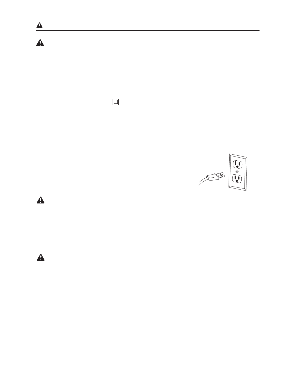
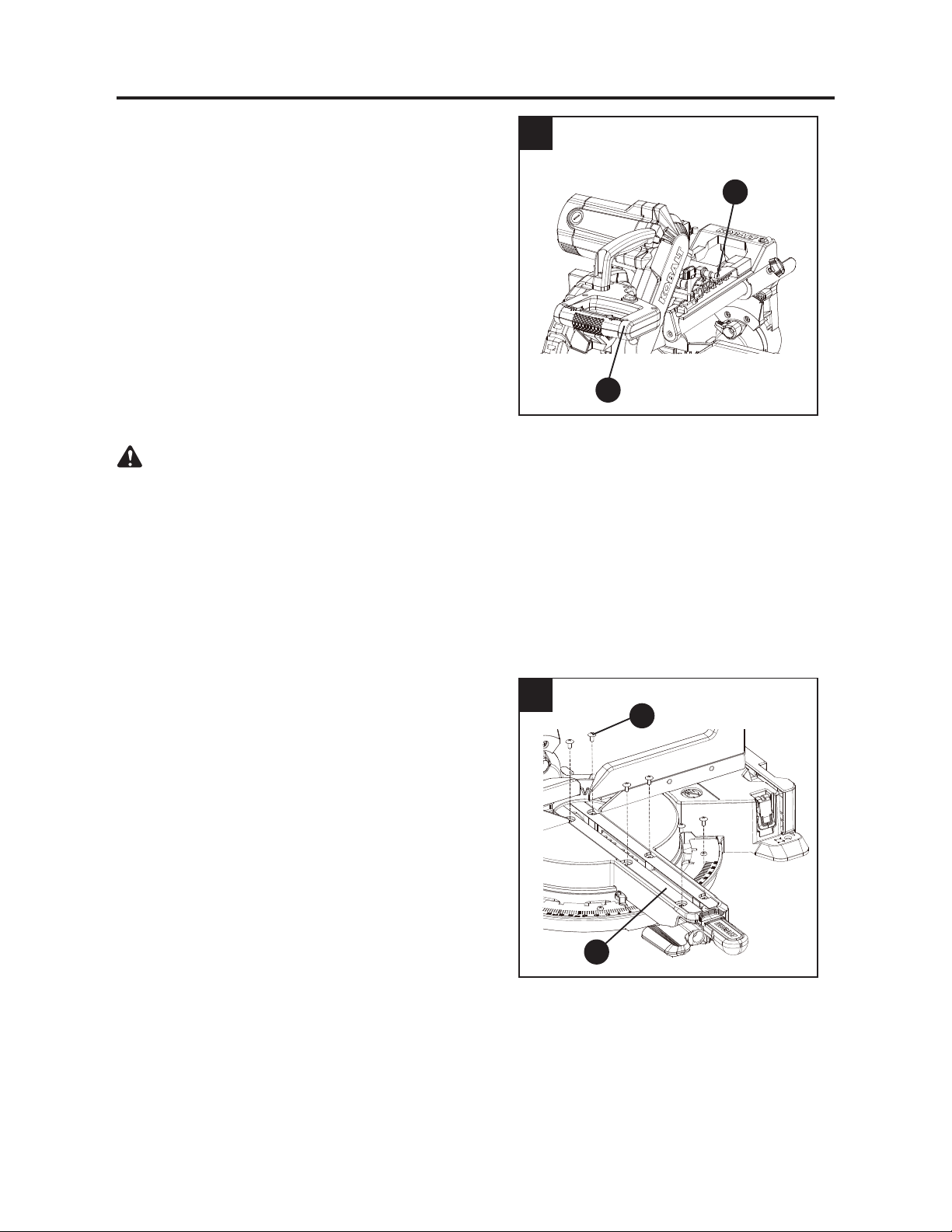
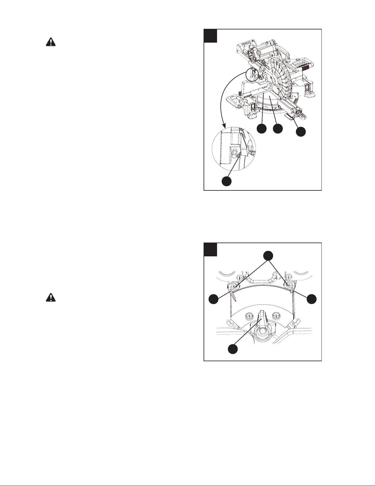
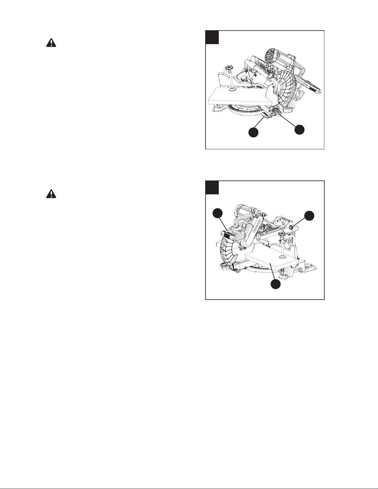
UNLOCKING THE SLIDE CARRIAGE (FIG. 1)
After removing the saw from the carton, loosen the
sliding carriage lock knob (V). When transporting
or storing the miter saw, the slide carriage should
always be locked in position. The sliding carriage
lock knob (V) is located on the right side of the slide
carriage.
INSTALLING THE BEVEL LOCK HANDLE (FIG. 2)
Insert the bevel lock handle (J) into the hole (1)
located at the front of the miter saw and secure in
place with the washer (2) and hex bolt (3) as shown
in Fig. 2.
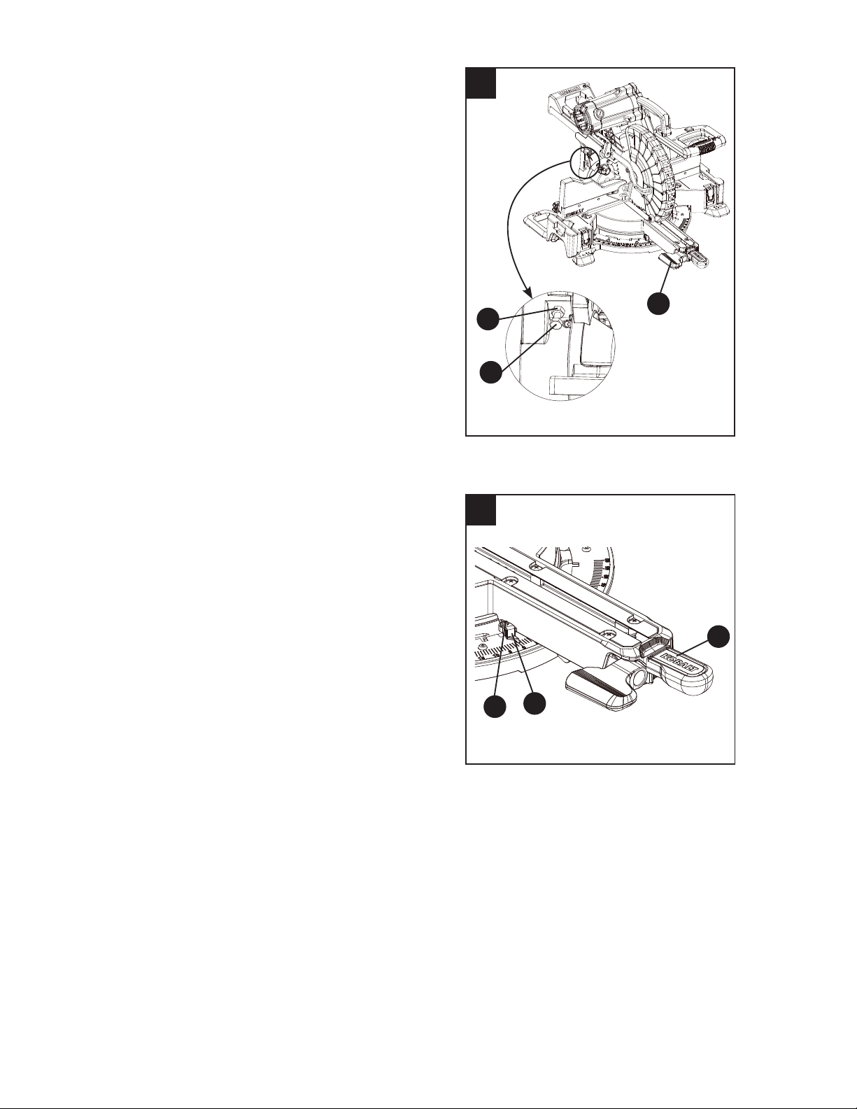
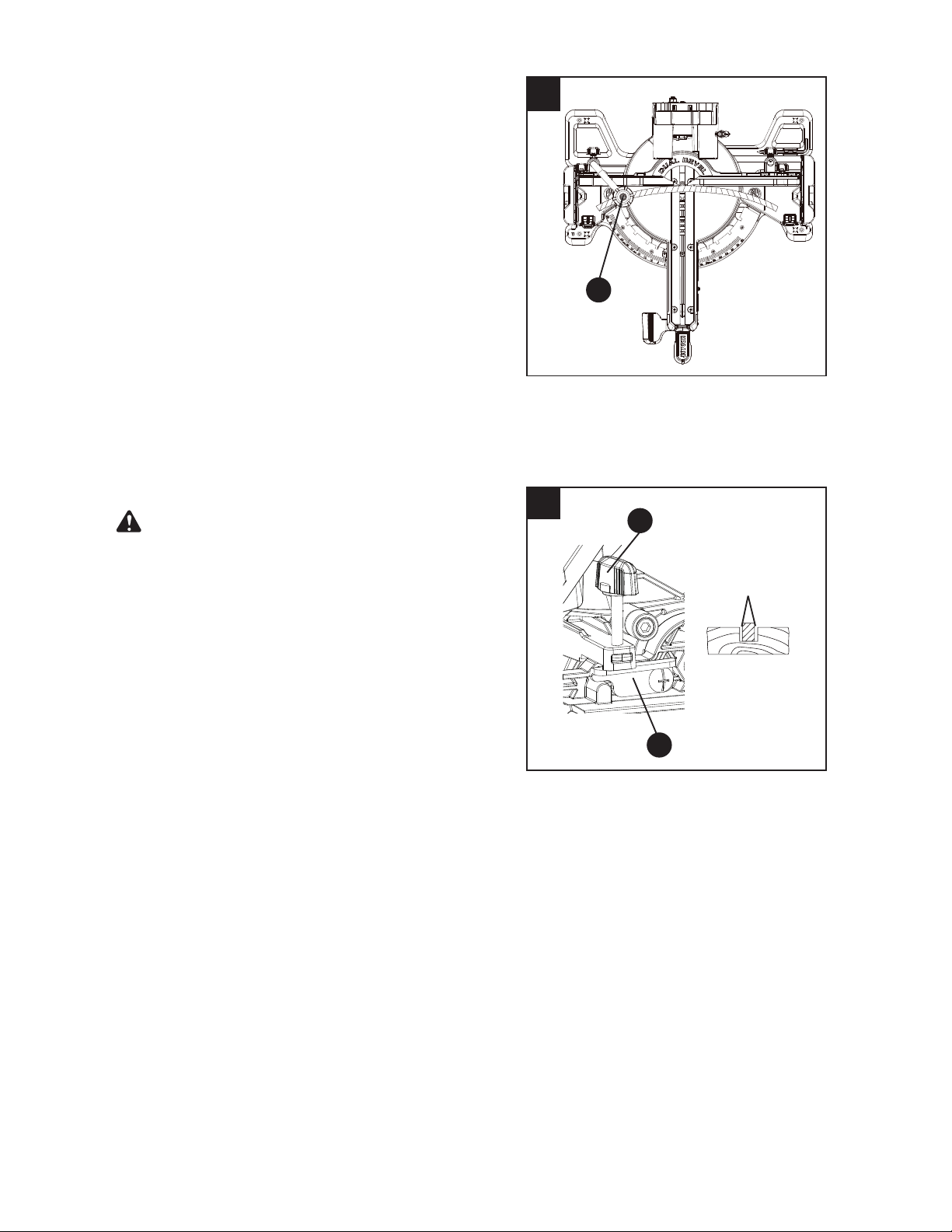
BLADE WRENCH (FIG. 3)
For convenient storage and prevention of loss, there
is a holder in the rear of the right side fence for
storing the blade wrench (E) when not in use.
Place the provided wrench in this location.
ASSEMBLY INSTRUCTIONS
1
2
3
V
E
J
1
2
3
WARNING
15
5
4
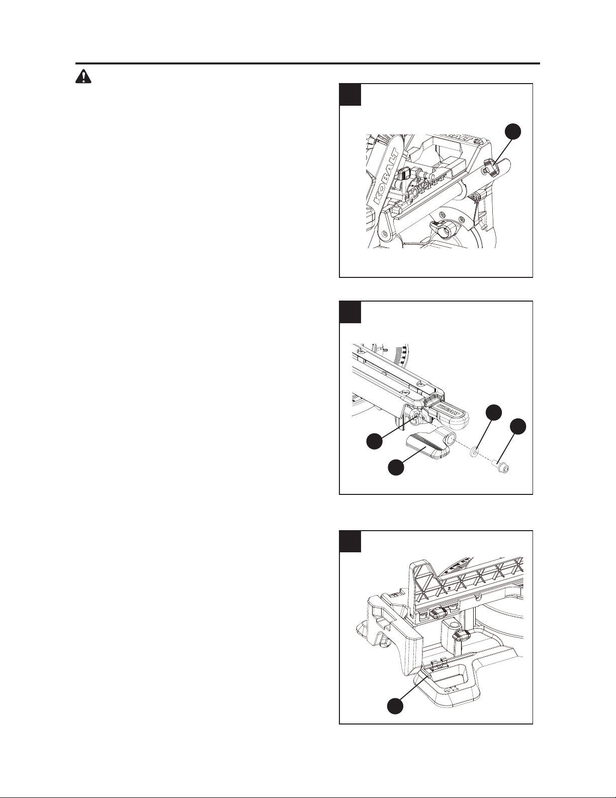
INSTALLING THE DUST BAG (FIG. 4)
ŏ Install the dust bag (C) onto the exhaust port
on the miter saw (A). Fit the connecting tube of
dust bag and the exhaust port together. The dust
bag assembly should be angled toward the side
of the saw (as shown in Fig. 4) for best results.
This will also avoid any interference during the saw
operation.
NOTE: To empty the dust bag, pull out the dust bag
from exhaust port. Open zipper on underside of bag
and empty into waste container.
IMPORTANT: Check frequently and empty bag
before it gets full.
Do not use this saw to cut and/or sand metals. The
hot chips or sparks may ignite sawdust from the bag
material.
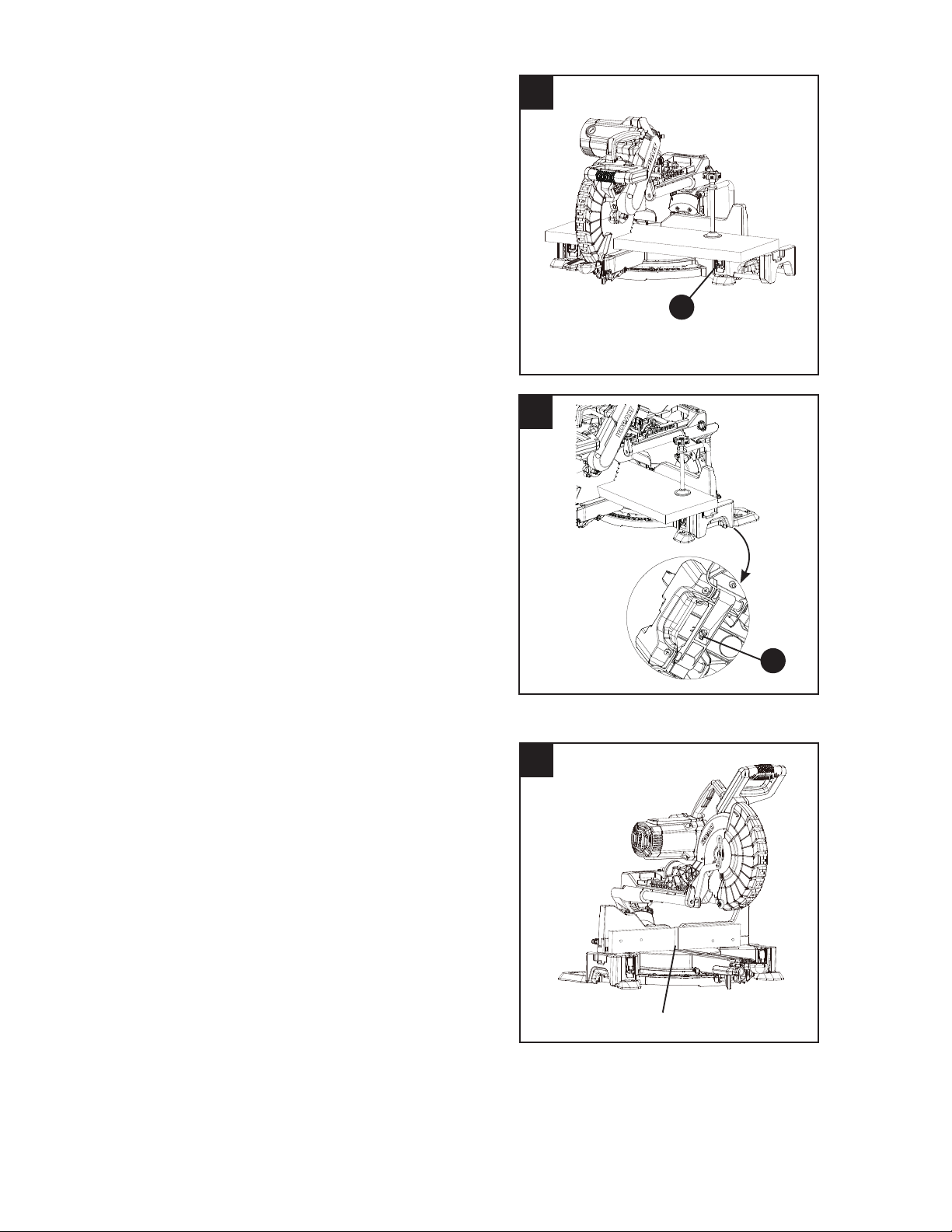
INSTALLING THE HOLD-DOWN CLAMP
(FIG. 5)
NOTE: There are two mounting holes for the
hold-down clamp. These are located just behind the
fence on the left and right side of the base.
ŏ Loosen the lock knob (1) behind the fence.
Ɣ 3ODFHWKHKROGGRZQFODPSDVVHPEO\%LQWKH
desired mounting holes.
Ɣ 7LJKWHQWKHORFNNQRE
NOTE:
Place the clamp on the opposite side of
the base when beveling. Always make dry runs
XQSRZHUHGEHIRUH¿QLVKFXWVWRFKHFNWKHSDWKRI
the blade. Ensure the clamp does not interfere with
the action of the saw or guards.
A
C
Hold-down clamp mounting holes
B
WARNING
1
16
6
UNLOCKING AND LOCKING THE CUTTING
HEAD (FIG. 6)
Unlocking the cutting head:
ŏ To raise the cutting head from its storage/
transport position, push down slightly on the
switch handle (F).
ŏ Pull out the hold-down latch (U).
ŏ Allow the cutting head to rise to the up position.
Locking the cutting head:
When transporting or storing the miter saw, the
cutting head should always be locked in the down
position.
ŏ Push the cutting head down to its lowest
position.
ŏ Push the hold-down latch (U) into the locking
hole.
To avoid injury and damage to the saw, transport
and store the miter saw with the cutting head locked
in the down position. Never use the stop latch to
hold the cutting head in a down position for cutting
operations.
IMPORTANT: To avoid damage, never carry the
miter saw by the switch handle, the cutting arm or
the miter table handle. ALWAYS use the hand
holds for transportation.
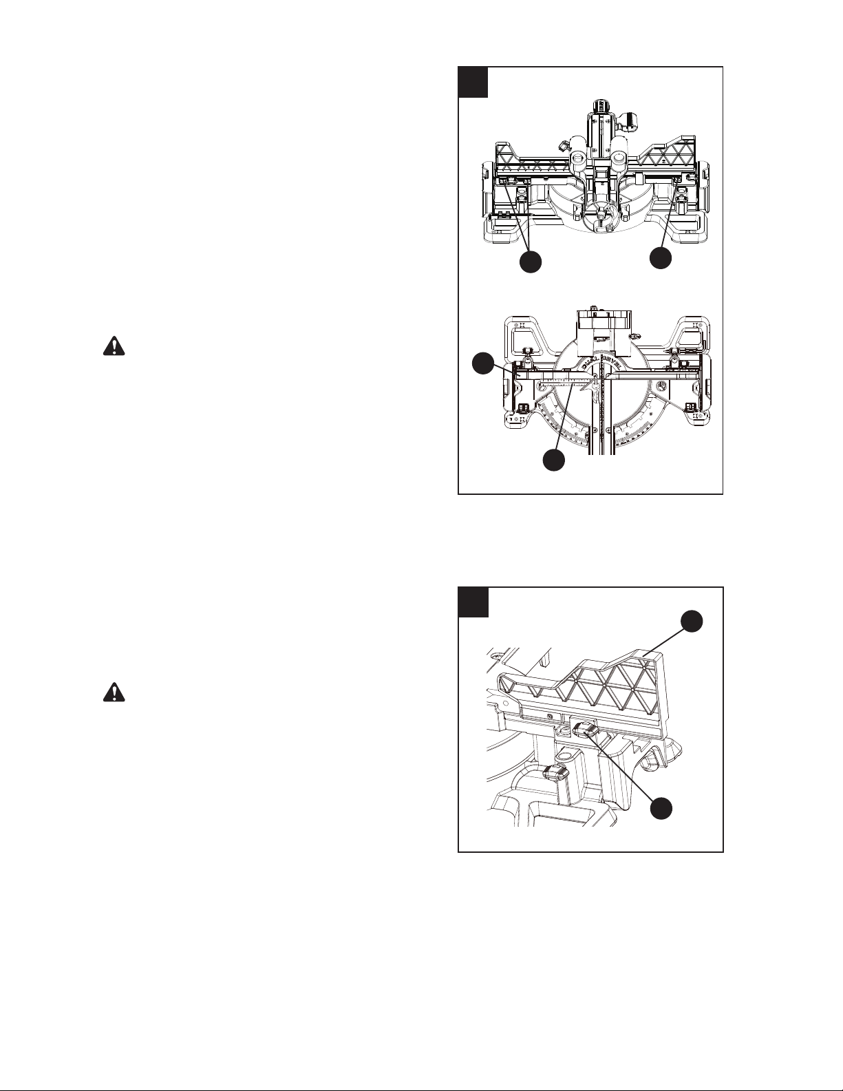
REMOVING AND INSTALLING THE TABLE
INSERTS (FIG. 7)
NOTE: The miter saw comes with the table
insert already installed. These instructions are for
replacing or adjusting the insert.
To avoid injury:
ŏ Always unplug the saw to avoid accidental
starting. Remove all small pieces of material
from the table cavity before performing any
cuts. The table insert may be removed for this
purpose, but always reattach the table insert
prior to performing a cutting operation.
ŏ Do not start the sliding compound miter saw
without checking for interference between the
blade and table insert. Damage could result
to the blade, table insert or turntable if a blade
strike occurs during the cutting operation.
ŏ To remove, loosen and remove the six
screws (1) on the table inserts (H) with a
Phillips screwdriver and remove the inserts.
ADJUSTMENT INSTRUCTIONS
7
1
H
F
U
CAUTION
17
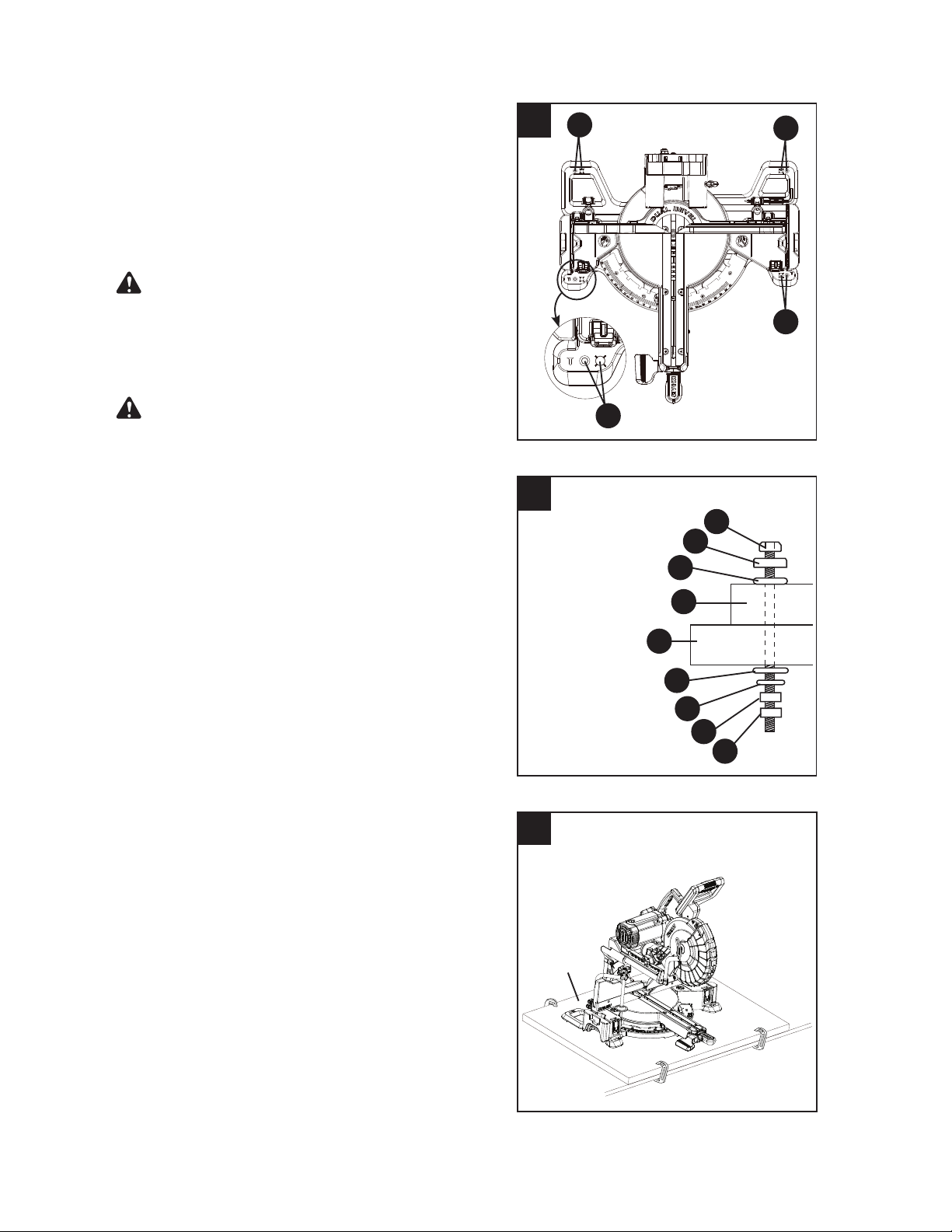
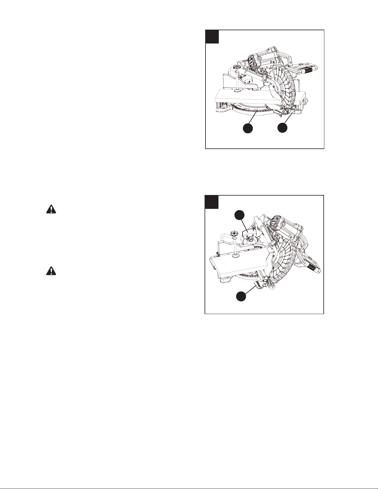
MOUNTING THE MITER SAW (FIG. 8, 9, 10)
To avoid injury from unexpected saw movement:
ŏ Disconnect the power cord from the outlet and
lock the cutting head in the lower position using
the hold-down latch.
ŏ Lock the slide carriage in place by tightening the
slide carriage lock knob.
ŏ To avoid back injury, lift the saw by using the
designated carrying handles located on the top
of the machine. Bend with your knees, not your
back.
ŏ Never carry the miter saw by the power cord
or by the switch handle. Carrying the tool by
the power cord could cause damage to the
insulation or the wire connections resulting in
HOHFWULFVKRFNRU¿UH
ŏ7RDYRLGLQMXU\IURPÀ\LQJGHEULVGRQRWDOORZ
visitors to stand near the saw during any cutting
operations.
Mounting instructions:
ŏ For stationary use, place the saw in the
desired location, directly on a workbench where
there is room for handling and proper support
of the workpiece. The base of the saw has eight
mounting holes (M-Fig. 8), four 2/5
in. and four
7/25 in. holes for mounting the saw to the work
surface. Bolt the base of the miter saw (1) to
the work surface (5), using the recommended
fastening method as shown in Fig. 9.
NOTE: Mounting hardware is not included with
this tool. Bolts, nuts, washers and screws must be
purchased separately.
9
10
Portable Use
3/4 in.
plywood
Stationary Use
1. Miter saw base
2. Hex head bolt
3. Rubber washer
4. Flat washer
5. Work surface
6. Flat washer
7. Lock washer
8. Hex/Lock nut
9. Jam nut
2
4
1
3
5
6
7
8
9
8
M
M
M
M
ŏ To install, reposition the left and right side
inserts on either side of the cut line, replace the
six screws and tighten.
ŏ Check for blade clearance by moving the slide
carriage through the full motion of the blade in
the table slot. If neither side of the insert hits
the saw blade, loosen the three screws for that
side and adjust. Tighten the screws and check
again for blade clearance.
Never use the saw without the table inserts in
place.
WARNING
WARNING
18
ŏFor portable use, place the saw on a
3/4 in. thick piece of plywood. Bolt the base of
the miter saw securely to the plywood using
the mounting holes (M-Fig. 8) on the base. Use
C-clamps to clamp this mounting board to a
stable work surface at the worksite. (Fig. 10)
NOTE: If a miter saw stand is used, please follow all
instructions shown in that product’s instructions for
proper mounting.
REMOVING AND INSTALLING THE BLADE
ŏUse only a saw blade diameter in accordance
with the markings on the saw.
ŏOnly use a 10 in. diameter blade with a 5/8 in.
arbor hole and an operating speed of more
than 4,450 RPM. Do not use blades with deep
JXOOHWV7KHVHFDQGHÀHFWDQGFRQWDFWWKH
guard, causing damage to the machine and/or
serious injury.
ŏTo avoid injury from an accidental start, make
sure the switch is in the OFF position and the
plug is not connected to the power source
outlet.
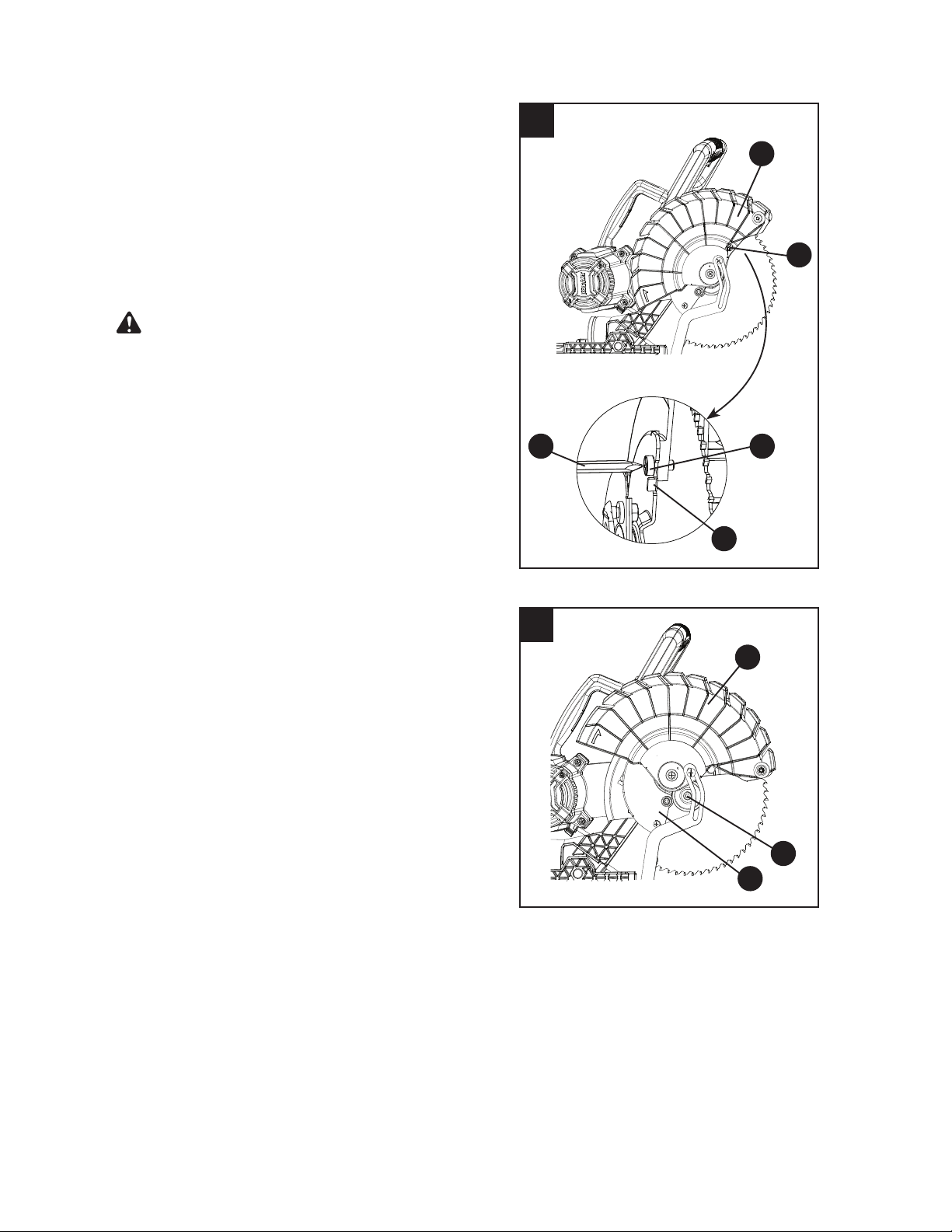
REMOVING THE BLADE (FIG. 11, 12, 13, 14, 15)
ŏ Unplug the saw from the outlet.
ŏ Raise the cutting head to its upright position as
shown in Fig. 11. Raise the lower blade
guard (G) to the up position shown in Fig. 11.
ŏ Loosen the cover plate screw (1) through the
hole by using the Phillips head end of the
provided blade wrench (D). Only loosen it
enough to position past the tab (2). (Fig. 11)
NOTE: Do not remove this screw.
ŏ Rotate the lower blade guard (G) back to its
down position about half way. The cover plate
screw (1-Fig. 11) should stop the guard from
moving any further and move the cover plate (3)
upward to expose the arbor bolt (4). (Fig. 12)
11
12
G
1
G
4
3
1
D
2
ŏ Place the hex end of the provided blade wrench (D) on the arbor bolt (4). (Fig. 13)
ŏ Locate the arbor lock button (EE) on the right side of saw, below the belt cover. (Fig. 14)
ŏ3UHVVWKHDUERUORFNEXWWRQ((KROGLQJLWLQ¿UPO\ZKLOHWXUQLQJWKHEODGHZUHQFKFORFNZLVH
The arbor lock will engage after turning the wrench, stopping the rotation of the blade.
Continue to hold the arbor lock button (EE) to keep it engaged while turning the wrench
clockwise to loosen the arbor bolt.
ŏ Remove the arbor bolt (4), the blade collar (5) and the blade (DD), as shown in Fig. 15. Do not
remove the inner blade collar (6).
NOTE: Pay attention to the pieces removed, noting their position and direction they face. Wipe the
blade collar clean of any sawdust before installing a new blade.
WARNING
19
13
14
15
INSTALLING THE BLADE (FIG. 11, 12, 13, 14, 15)
Unplug the miter saw before changing/installing the
blade.
ŏ Install a 10 in. blade with a 5/8 in. arbor, making
sure the rotation arrow on the blade matches
the clockwise rotation arrow on the upper guard.
ŏ Place the outer blade collar (5) against the
blade and on the arbor. Thread the arbor bolt (4)
onto the arbor in a counterclockwise direction.
(Fig. 15)
IMPORTANT:0DNHVXUHWKHÀDWVRIWKHEODGH
FROODUVDUHHQJDJHGZLWKWKHÀDWVRQWKHDUERU
VKDIW$OVRWKHÀDWVLGHRIWKHEODGHFROODUPXVW
be placed against the blade.
ŏ Place the hex end of blade wrench (D) on the
arbor bolt (4). (Fig. 13)
ŏ Press the arbor lock button (EE), holding it in
¿UPO\ZKLOHWXUQLQJWKHEODGHFRXQWHUFORFNZLVH
When arbor lock engages, continue to
press it in while turning the blade wrench
counterclockwise, tightening the arbor bolt
securely. (Fig. 14)
ŏ Rotate the lower blade guard (G) to its up
position. The cover plate should move to its
original position.
Then tighten the cover plate
screw (1) through the hole with the Phillips head
end of provided blade wrench. (Fig. 11)
ŏ Lower the blade guard (G) and verify that the
operation of the guard does not bind or stick.
ŏ Be sure the arbor lock is released so the blade
turns freely before operating the saw.
ŏ To avoid injury, never use the saw without the
cover plate securely in place. It keeps the arbor
bolt from falling out if it accidentally loosens and
helps prevent the spinning blade from coming
RႇWKHVDZ
ŏ Make sure the collars are clean and properly
arranged. Lower the blade into the lower table
and check for any contact with the metal base
or the miter table.
ŏ To avoid injury from an accidental start, make
sure the switch is in the OFF position and the
plug is not connected to the power source outlet.
ŏNever cut metals or masonry products with this
tool. This miter saw is designed for use on wood
and wood-like products only.
4
5
6
DD
EE
G
3
4
D
DO NOT
REMOVE
Always make dry runs (unpowered)
EHIRUH¿QLVKFXWVWRFKHFNWKHSDWKRIWKHEODGHDQG
the operation of the guards.
WARNING
WARNING:
20
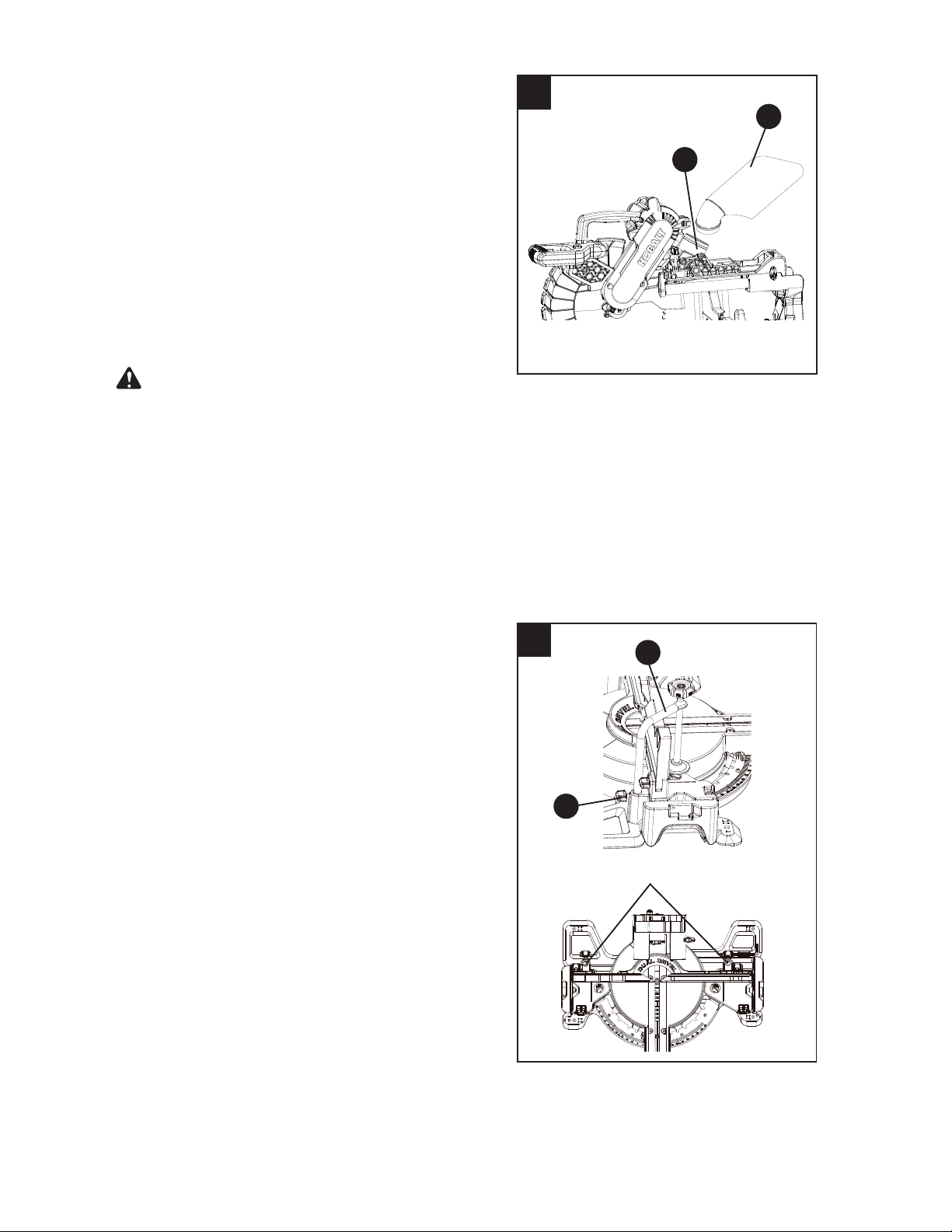
BEVEL STOP ADJUSTMENT (FIG. 16, 17, 18)
To avoid injury from an accidental start, make sure
the switch is in the OFF position and the plug is not
connected to the power source outlet.
90° (0°) Bevel Adjustment (Fig. 16):
ŏ Loosen bevel lock handle (J) and tilt the cutting
arm completely to the right. Tighten the bevel
lock handle (J).
ŏ Place a combination square (1) on the miter
table with the ruler against the table and the
heel of the square against the saw blade.
ŏ If the blade is not 90° square with the miter
table (BB), loosen the bevel lock handle (J), tilt
the cutting head to the right by pulling out the
right bevel detent pin (X-Fig. 17), adjust
the
bevel angle adjustment bolt (2) in or out with a
3 mm wrench until the blade is square with
the table.
ŏ Tilt the cutting arm back to 90°(0°) bevel and
recheck for alignment.
ŏ Repeat above steps if further adjustment is
needed.
ŏ Tighten bevel lock handle (J) when alignment is
achieved.
90° Bevel Pointers Adjustment (Fig. 17):
ŏ When the blade is exactly 90° to the table,
loosen the bevel pointer screws (1) using a
Phillips screwdriver.
ŏ Adjust bevel angle pointers (P) to the “0” mark
on the bevel scale and retighten the screw.
To avoid injury from an accidental start, make sure
the switch is in the OFF position and the plug is not
connected to the power source outlet.
16
2
J
BB
1
17
1
P
X
P
WARNING
WARNING
21
Left/Right 45° Bevel Adjustment (Fig. 18):
ŏ Loosen the bevel lock handle (J) by lifting up
and tilt the cutting head completely to the left.
ŏ Using a combination square, check to see if the
blade angle is 45° to the table.
ŏ If the blade is not at 45° to the miter table, tilt
the cutting arm to the right, loosen the jamb
nut (1) and turn the bevel angle adjustment
bolt (2) in or out with a 10 mm
wrench.
ŏ Tilt the cutting arm to the left 45° bevel and
recheck for alignment.
ŏ Repeat above until the blade is at 45° to the
miter table.
ŏ Tighten bevel lock handle (J) and jamb
nut (1) when alignment is achieved.
ŏ Adjust the 45° bevel on the other side following
the same steps listed above.
MITER SCALE (FIG. 19)
The sliding compound miter saw scale can be easily
read, showing miter angles from
0° to 55° left and
0° to 60° right. The most common angle settings
have positive stops at 0°,15°, 22.5°, 31.6°, 45° left
and right, 55° left and 60° right only. These positive
stops position the blade at the desired angle quickly
and accurately. Follow the instructions below for
quickest and most accurate adjustments.
To Adjust Miter Angles:
ŏ Lift up the miter lock handle (I) to unlock
the table.
ŏ Move the table to align the pointer (K) to the
desired degree measurement.
ŏ If the desired angle is one of the eleven positive
stops, making sure it snaps into position,
then secure by pressing down the miter lock
handle (I) to make it in a horizontal position.
ŏ If the miter angle desired is not one of the
eleven positive stops, simply lock the miter table
into position by pressing down the miter lock
handle (I).
Miter Angle Pointer Adjustment (Fig. 19):
ŏ Move the table to the 0° positive stop.
ŏ Loosen the screw (1) that holds the
pointer (K) with a Phillips screwdriver.
ŏ Adjust the pointer (K) to the 0° mark and
retighten the screw (1).
19
I
K
1
18
2
1
J
22
ADJUSTING FENCE SQUARENESS (FIG. 20)
ŏ Lower the cutting arm and lock in position.
ŏ Loosen the three fence locking bolts (1) using a
5 mm
wrench.
ŏ Using a square (2), lay the heel of the square
against the blade and the ruler against the
fence (Y) as shown.
ŏ Adjust the fence to be 90° to the blade and
tighten the three fence locking bolts (1).
NOTE: If the saw has not been used recently,
recheck blade squareness to the fence and
readjust if needed.
ŏ After fence has been aligned, make a cut at 90
o
using a scrap of wood and check squareness on
the piece. Readjust if necessary.
20
2
Y
1
1
Always make dry runs (unpowered)
EHIRUH¿QLVKFXWVWRFKHFNWKHSDWKRIWKHEODGHDQG
the operation of the guards. Ensure the fence does
not interfere with the action of the saw or guards.
WARNING:
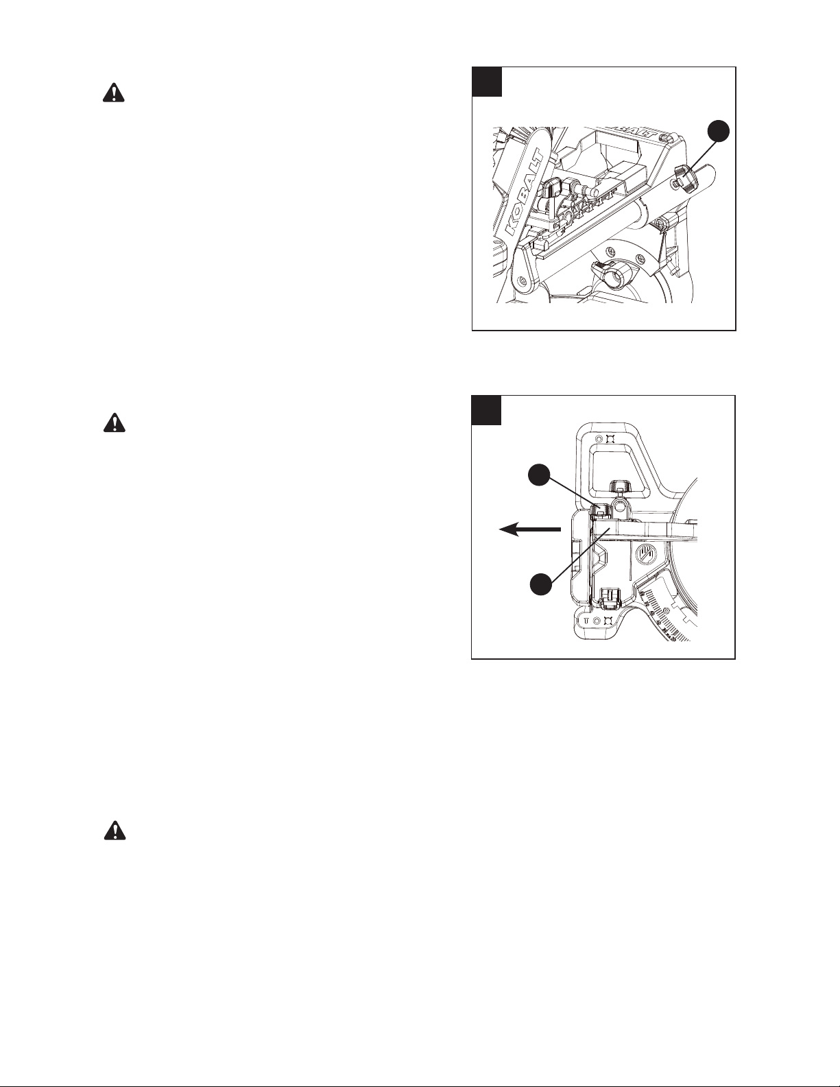
REMOVING OR INSTALLING THE SLIDING
FENCE (FIG. 21)
At some extreme angles, the right or left side
fence might have to be removed to ensure
proper clearance prior to making the cut.
The side sliding fence must be removed when
making any bevel angle cuts greater than 33.9°
in combination with any miter angle cuts greater
than 31.6°.
Ɣ 7RUHPRYHWKHVOLGLQJIHQFHloosen the fence
locking knob (1) by turning it counterclockwise,
then slide the fence (O) out from the fence slot.
Ɣ 7RLQVWDOOWKHVOLGLQJIHQFHVOLGHWKHVOLGLQJ
fence into the fence slot, then lock the fence by
turning the fence locking knob (1) clockwise.
NOTE: This miter saw is equipped to cut wide
boards up to 12 in., see section SLIDE CUTTING
WIDE BOARDS on page 31.
21
1
O
CAUTION
23
22
SETTING CUTTING DEPTH (FIG. 22)
The depth of cut can be preset for even and
repetitive shallow cuts.
ŏ Adjust the cutting head down until the teeth of
the blade is at the desired depth.
ŏ While holding the upper arm in that position, turn
the cutting depth stop knob (T) until it touches
the stop plate (1).
ŏ Recheck the blade depth by moving the cutting
head front to back through the full motion of a
typical cut along the control arm.
NOTE: Use a wooden spacer between the
fence and the workpiece for a consistent depth
through the cut. Use the hold-clamp to secure
WKHZRRGHQVSDFHUDQGZRUNSLHFH¿UPO\EHIRUH
making a cut.
MAXIMUM CUTTING DEPTH (FIG. 22)
The maximum depth travel of the cutting head was
set at the factory.
Ɣ 5RWDWHWKHVWRSSODWHFORFNZLVHWRWRXFKWKH
stop rod (2).
Ɣ 5HFKHFNWKHEODGHGHSWKE\PRYLQJWKHFXWWLQJ
head front to back through the full motion of a
typical cut along the control arm.
T
1
2

24
OPERATING INSTRUCTIONS
BEFORE USING THE MITER SAW
To avoid mistakes that could cause serious, permanent injury, do not plug the tool in until the
following steps are completed:
ŏ Completely assemble and adjust the saw, following the instructions (SEE ASSEMBLY AND
ADJUSTMENTS SECTIONS).
ŏ Learn the use and function of the ON/OFF switch, upper and lower blade guards, stop latch,
bevel lock handle and cover plate screws.
ŏ Review and understand all safety instructions and operating procedures in this Operator’s
Manual (SEE SAFETY & OPERATIONS SECTIONS).
ŏ Review the MAINTENANCE and TROUBLESHOOTING for your miter saw.
ŏ 7RDYRLGLQMXU\RUSRVVLEOHGHDWKIURPHOHFWULFDOVKRFNPDNHVXUH\RXU¿QJHUVGRQRWWRXFK
the plug’s metal prongs when plugging or unplugging your miter saw (SEE ELECTRICAL
REQUIREMENTS AND SAFETY SECTIONS).
BEFORE EACH USE
Inspect your saw.
ŏ Disconnect the miter saw. To avoid injury from accidental starting, unplug the saw before
making any adjustments, including setup and blade changes.
ŏ Compare the direction of rotation arrow on the guard to the direction arrow on the blade. The
blade teeth should always point downward at the front of the saw.
ŏ Tighten the arbor bolt.
ŏ Tighten the cover plate screw.
ŏ Check for damaged parts, including:
Ɇ Alignment of moving parts
Ɇ Damaged blade teeth
Ɇ Damaged electric cords
Ɇ Binding of moving parts
Ɇ Broken/cracked castings: base, table, motor, upper arm
ŏ Function of arm return spring and lower guard: Push the cutting arm all the way down and
then let it rise until it stops. The lower guard should close fully. Follow the instructions in the
Troubleshooting Guide for adjustment, if necessary.
ŏ Keep all guards in place, in working order and properly adjusted. If any part of this miter saw
LVPLVVLQJGDPDJHGRUEURNHQRUDQ\HOHFWULFDOSDUWVGRQRWZRUNWXUQRႇWKHVDZDQGXQSOXJ
it. Replace damaged, missing or defective parts before using the saw again.
ŏ Maintain tools with care. Keep the miter saw clean for best and safest performance. Follow
instructions for lubricating. Do not apply lubricants to the blade while it is spinning.
ŏ Remove all adjusting wrenches from the tool before turning it on.
USE ONLY THE RECOMMENDED ACCESSORIES
ŏ Follow the instructions that come with the accessory. The use of improper accessories may
cause risk of injury to persons.
ŏ Choose the correct 10 in. blade for the material and the type of cutting you plan to do.
ŏ Make sure the blade is sharp, undamaged and properly aligned. With the saw unplugged,
push the cutting arm all the way down. Manually spin the blade and check for clearance. Tilt
the miter head to a 45° bevel and repeat the test.
ŏ Make sure the blade and arbor collars are clean.
ŏ Make sure all clamps and locks are tight and there is no excessive play in any parts.
WARNING

25
KEEP YOUR WORK AREA CLEAN
Cluttered areas and benches invite accidents.
7RDYRLGEXUQVRURWKHU¿UHGDPDJHQHYHUXVHWKHPLWHUVDZQHDUÀDPPDEOHOLTXLGVYDSRUVRU
gases.
ŏ Plan ahead to protect your eyes, hands, face and ears.
ŏ 5HDGDQGXQGHUVWDQGWKHRSHUDWRU¶VPDQXDODQGODEHOVDႈ[HGWRWKHWRRO/HDUQLWV
DSSOLFDWLRQDQGOLPLWDWLRQVDVZHOODVWKHSRWHQWLDOKD]DUGVVSHFL¿FWRWKLVWRRO7RDYRLGLQMXU\
from accidental contact with moving parts, do not layout, assemble or set up work on the
miter saw.
ŏ Avoid accidental starting. Make sure the switch is in the OFF position before plugging the
miter saw into a power outlet.
PLAN YOUR WORK
Use the right tool. Do not force a tool or attachment to do a job it was not designed to do. Use a
GLႇHUHQWWRROIRUDQ\ZRUNSLHFHWKDWFDQQRWEHKHOGLQDVROLGO\EUDFHG¿[HGSRVLWLRQ
This machine is NOT designed for cutting masonry, masonry products or ferrous metals (steel,
iron and iron-based metals). Use this miter saw to cut only wood and wood by-products. Other
materials may shatter, bind the blade or create other dangers. Remove all nails that may be in the
ZRUNSLHFHWRSUHYHQWVSDUNLQJWKDWFRXOGFDXVHD¿UH
DRESS FOR SAFETY
Any power tool can throw foreign objects into the eyes. This can result in permanent eye damage.
Everyday eyeglasses have only impact resistant lenses and are not safety glasses. Glasses or
goggles not in compliance with ANSI Z87.1 could seriously injure you if they break.
ŏ Do not wear loose clothing, gloves, neckties or jewelry (rings, watches). They can get caught
and draw you into moving parts.
ŏ Wear non-slip footwear.
ŏ Tie back long hair.
ŏ Roll long sleeves above the elbow.
ŏ Noise levels vary widely. To avoid possible hearing damage, wear earplugs when using any
miter saw.
ŏ For dusty operations, wear a dust mask along with safety goggles.
INSPECT YOUR WORKPIECE
ŏ Make sure there are no nails or foreign objects in the part of the workpiece being cut.
ŏ Plan your work to avoid small pieces that may bind or are too small to clamp and hold
securely.
ŏ 3ODQWKHZD\\RXZLOOJUDVSWKHZRUNSLHFHIURPVWDUWWR¿QLVK$YRLGDZNZDUGRSHUDWLRQVDQG
KDQGSRVLWLRQV$VXGGHQVOLSFRXOGFDXVH\RXU¿QJHUVRUKDQGWRPRYHLQWRWKHEODGH
DO NOT OVERREACH
Keep good footing and balance. Keep your face and body to one side, out of the line of a possible
kickback. NEVER stand in the line of the blade.
WARNING
WARNING

26
Never cut freehand:
ŏ %UDFH\RXUZRUNSLHFH¿UPO\DJDLQVWWKHIHQFHDQGWDEOHVWRSVRLWZLOOQRWURFNRUWZLVWGXULQJ
the cut.
ŏ Make sure there is no debris between the workpiece and the table or fence. Make sure there
are no gaps between the workpiece, fence and table that will let the workpiece shift after it is
cut.
ŏ .HHSWKHFXWSLHFHIUHHWRPRYHVLGHZD\VDIWHULWLVFXWRႇ2WKHUZLVHLWFRXOGJHWZHGJHG
against the blade and thrown violently.
ŏ Only the workpiece should be on the saw table.
ŏ Secure work. Use clamps or a vise to help hold the work when it is practical.
USE EXTRA CAUTION WITH LARGE OR ODD SHAPED WORKPIECES
ŏ Use extra supports (tables, sawhorses, blocks, etc.) for workpieces large enough to tip.
ŏ Never use another person as a substitute for a table extension or as an additional support for a
workpiece that is longer or wider than the basic miter saw table, or to help feed, support or pull
the workpiece.
ŏ Do not use this saw to cut small pieces. If the workpiece being cut would cause your hand or
¿QJHUVWREHZLWKLQLQRIWKHVDZEODGHWKHZRUNSLHFHLVWRRVPDOO.HHSKDQGVDQG
¿QJHUVRXWRIWKH³QRKDQGV]RQH´DUHDPDUNHGRQWKHVDZWDEOH
ŏ When cutting odd shaped workpieces, plan your work so it will not bind in the blade and cause
SRVVLEOHLQMXU\0ROGLQJIRUH[DPSOHPXVWOLHÀDWRUEHKHOGE\D¿[WXUHRUMLJWKDWZLOOQRWOHWLW
move when cut.
ŏ Properly support round material such as dowel rods or tubing, which have a tendency to roll
when cut, causing the blade to “bite.”
WHEN SAW IS RUNNING
Do not allow familiarity from frequent use of your miter saw to result in a careless mistake.
A careless fraction of a second is enough to cause severe injury.
Before cutting, if the saw makes an unfamiliar noise or vibrates, stop immediately. Turn the saw
2))8QSOXJWKHVDZ'RQRWUHVWDUWXQWLO\RX¿QGDQGFRUUHFWWKHSUREOHP
To ensure the blade path is clear of obstructions, always make a dry run of the cut without power
before making any cuts on the workpiece.
WARNING
WARNING
27
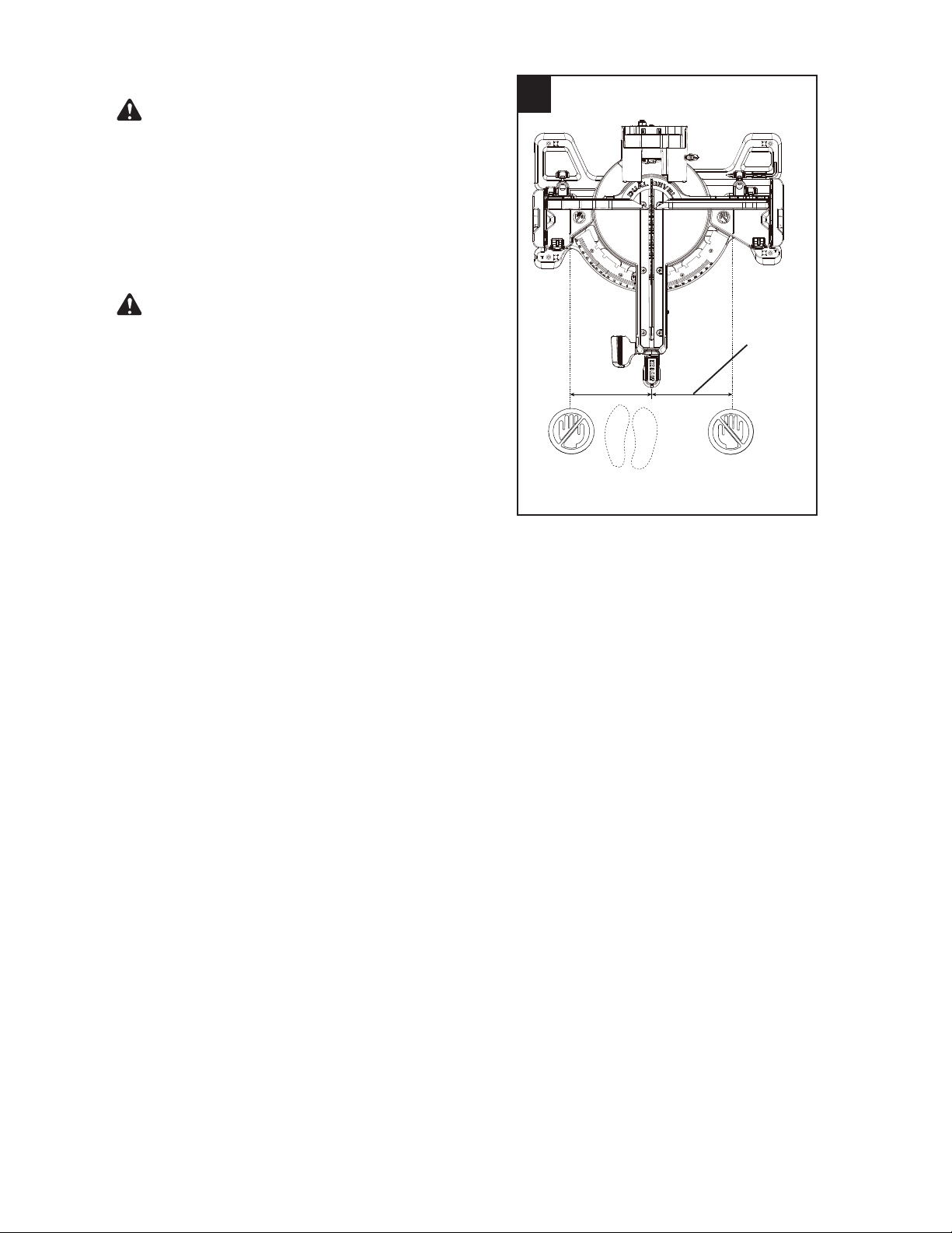
BODY AND HAND POSITION (FIG. 23)
Never place hands near the cutting area. Proper
positioning of your body and hands when operating
the miter saw will make cutting easier and safer.
Keep children away. Keep all visitors at a safe
distance from the miter saw. Make sure bystanders
are clear of the saw and workpiece. Do not force the
saw. It will do the job better and safer at its designed
rate.
Operator and all by-standers must wear proper
safety goggles that comply with OSHA/ANSI
requirements Z87.1.
Starting a cut:
Ɣ Place hands at least 7-7/10 in. away
from the path of the blade – out of the
“no-hands zone.”
Ɣ +ROGZRUNSLHFH¿UPO\DJDLQVWWKHIHQFHWR
prevent movement toward the blade.
Ɣ Turn the LED switch on for pre-alignment of
your cut.
Ɣ With the power switch OFF, bring the saw blade
down to the workpiece to see the cutting path of
the blade. Raise the saw blade back up before
turning the saw on.
Ɣ Squeeze trigger switch to start saw.
Ɣ /RZHUEODGHLQWRZRUNSLHFHZLWKD¿UP
downward motion.
Ɣ 2QZLGHUERDUGVVOLGHWKHFXWWLQJDUPEDFN
toward fence to make the cut.
Finishing a cut:
ŏ Hold the cutting arm in the down position.
ŏ Release trigger switch and wait for all moving
parts to stop before moving your hands and
raising the cutting arm.
ŏ If the blade doesn’t stop within 5 seconds,
unplug the saw and follow the instructions in
TROUBLESHOOTING.
Before freeing jammed material:
ŏ Release trigger switch.
ŏ Wait for all moving parts to stop.
ŏ Unplug the miter saw.
23
7-7/10 in.
7-7/10 in.
No-hands
zone
WARNING
WARNING
28
BASIC SAW OPERATIONS
For your convenience, your saw has a blade brake.
The brake is not a safety device. Never rely on it to
replace the proper use of the guard on your saw.
If the blade doesn’t stop within approximately 5
seconds, wait for the blade to stop, unplug the saw
and follow the instructions in TROUBLESHOOTING.
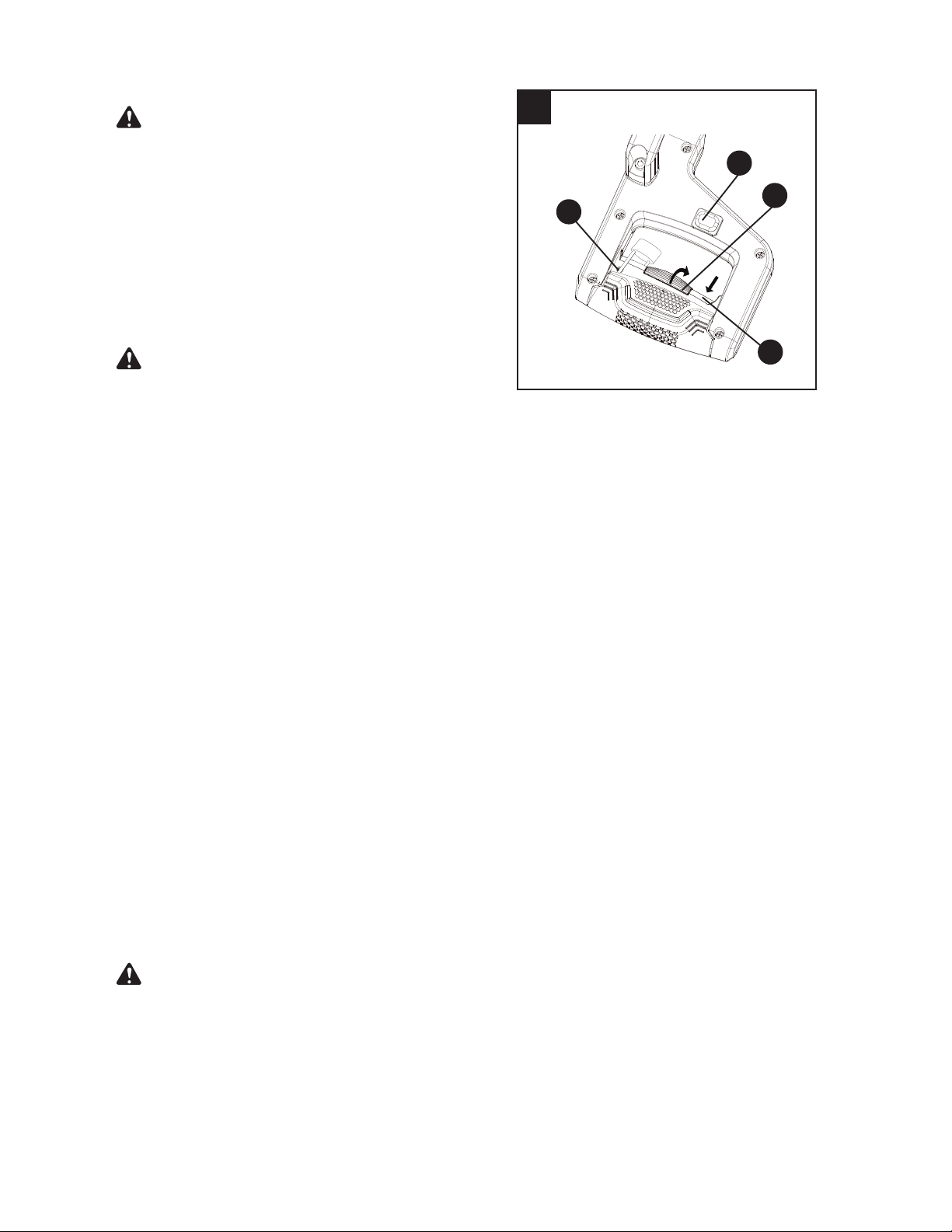
TURNINH THE LED LIGHT ON (FIG. 24)
Press the LED ON/OFF switch (FF) to “ON” position
to turn the light on.
Do not stare into the light beam (not even from a
distance). Staring into the light beam may result
in serious injury or vision loss.
The LED casts a shadow of the blade teeth onto
the workpiece for making precision cuts and
predicts blade kerf for blade cut line.
To use this feature, turn the LED ON/OFF
switch (FF) on. Bring the cutting head down, and
the shadow of the blade will be projected onto
the workpiece, indicating where the blade teeth
will make contact as the cut is made.
TO TURN SAW ON (FIG. 24)
This miter saw is equipped with a two step ON/OFF
trigger switch. Press down on the yellow safety lock
switch (1) and squeeze the trigger switch (2) to turn
the miter saw ON.
NOTE: Make the ON/OFF switch childproof. Insert
a padlock (not included) through the hole (3) in
the trigger switch, locking the tool’s switch and
preventing children and other unauthorized users
from turning the machine on.
The miter saw is equipped with an electric brake.
When the trigger switch is released, the electric
blade brake will stop the blade within 5 seconds.
ŏ To avoid injury, after completing a cut and
UHOHDVLQJWKHWULJJHUVZLWFKZDLWDQGFRQ¿UP
the blade has stopped before raising the cutting
head.
ŏ To avoid injury, check and tighten the arbor bolt
periodically.
24
2
FF
3
1
WARNING
WARNING
WARNING
29
26
1
O
SLIDING CARRIAGE SYSTEM (FIG. 25)
To reduce the risk of injury, return carriage to the
full rear position after each crosscut operation.
ŏ For chop cutting operations on small workpieces,
slide the cutting head assembly completely
toward the rear of the unit and tighten the sliding
carriage lock knob (V).
ŏ To cut wide boards up to 12 in., the carriage lock
knob must be loosened to allow the cutting head
to slide freely.
NOTE: Please refer to the section of “SLIDE
CUTTING WIDE BOARDS” on page 31 to cut wide
boards up to 12 in.
SLIDING FENCE (FIG. 26)
The sliding fence must be extended when making
any bevel cut. Failure to extend the sliding fence
will not allow enough space for the blade to pass
through, which could result in serious injury. At
extreme miter or bevel angles, the saw blade may
also contact the fence.
ŏ Loosen the fence locking knob (1) by turning it
counterclockwise, then slide the fence (O) out.
ŏ Tighten the fence locking knob (1).
NOTE: When transporting the saw, always
secure the sliding fence in the inward position
and locked.
BEFORE LEAVING THE SAW
ŏ Never leave tool running unattended. Turn
power OFF. Wait for all moving parts to stop.
ŏ Make workshop childproof. Lock the shop.
Disconnect master switches. Store tool away
IURPFKLOGUHQDQGRWKHUXQTXDOL¿HGXVHUV
To avoid injury from materials being thrown, always
unplug the saw to avoid accidental starting and
remove small pieces of material from the table
cavity.
25
V
CAUTION
WARNING
WARNING
30
MITER CUT (FIG. 27)
ŏ When a miter cut is required, unlock the miter
table by lifting up the miter lock handle (I).
ŏ Rotate the miter table to the right or left with the
miter handle.
ŏ When the table is in the desired position, as
shown on the miter scale (L), pressing down the
miter handle to make it in a horizontal position to
tighten the miter table. The table is now locked
at the desired angle. Positive stops are provided
at 0°, 15°, 22.5°, 31.6°, 45° left and right, 55°
left and 60° right.
Ɣ 7XUQWKH/('VZLWFKRQDQGSRVLWLRQWKHZRUNSLHFH
on the table for pre-alignment of your cut.
IMPORTANT: Always tighten the miter lock handle
before performing every cutting operation.
BEVEL CUT (FIG. 28)
The sliding fence must be extended when making
any bevel cut. Failure to extend the sliding fence
will not allow enough space for the blade to pass
through which could result in serious injury. At
extreme miter or bevel angles, the saw blade may
also contact the fence.
The side sliding fence must be removed when
making any bevel angle cuts greater than 33.9°
in combination with any miter angle cuts greater
than 31.6°.
ŏ When a bevel cut is required, loosen the bevel
lock handle (J) by turning it clockwise.
ŏ Tilt the cutting head to the desired angle, as
shown on the bevel scale (W).
ŏ The blade can be positioned at any angle, from a
90° straight cut (0° on the scale) to a 48° left/right
bevel. Tighten the bevel lock handle (J) to lock
the cutting head in position. Positive stops are
provided at 0° and 45°.
Ɣ 7XUQWKH/('VZLWFKRQDQGSRVLWLRQWKHZRUNSLHFH
on the table for pre-alignment of your cut.
27
I
L
28
W
J
WARNING
WARNING
31
COMPOUND CUT (FIG. 29)
The side sliding fence must be removed when making
any bevel angle cuts greater than 33.9° in combination
with any miter angle cuts greater than 31.6°.
A compound cut is the combination of a miter and a
bevel cut simultaneously.
ŏ Extend the sliding fence as described in
“SLIDING FENCE” section on page 29.
ŏ Loosen the bevel lock handle (J) and position
the cutting head at the desired bevel position.
Lock the bevel lock handle (J).
ŏ Loosen the miter lock handle (I) by lifting it up.
Position the table at the desired miter angle. Lock
the miter lock handle (I) by pressing it down.
Ɣ 7XUQWKH/('VZLWFKRQDQGSRVLWLRQWKHZRUNSLHFH
on the table for pre-alignment of your cut.
SLIDE CUTTING WIDE BOARDS (FIG. 30)
Always use a work clamp to maintain control and
reduce the risk of workpiece damage and personal
injury.
To avoid injury:
ŏ Let the blade reach full speed before cutting. This
will help reduce the risk of a thrown workpiece.
ŏ Do not make crosscuts by lowering the blade
and pulling the saw head through the wood
toward you. The blade may try to climb up on top
of the workpiece, causing the cutting assembly
and spinning blade to kick back forcefully.
To slide cut wide boards (Fig. 30)
ŏ Unlock the sliding carriage lock knob (V) and
allow the cutting head assembly to move freely.
ŏ Set both the desired bevel angle and/or the
miter angle and lock into position.
ŏ Use a hold-down clamp to secure the
workpiece (1).
ŏ Grasp the switch handle (F) and pull forward
until the center of the saw blade is over the front
of the workpiece (1).
ŏ Engage the trigger to turn the saw on.
ŏ When the saw reaches full speed, slowly push
the saw handle down, cutting through the
leading edge of the workpiece (1).
ŏ Slowly move the saw handle back toward the
fence, completing the cut.
ŏ Release the trigger and allow the blade to stop
spinning before raising the cutting head and
removing the workpiece (1).
29
I
J
30
V
F
1
CAUTION
!
WARNING
32
CUTTING BOWED MATERIAL (FIG. 31)
A bowed workpiece must be positioned against the
fence and secured with a clamp (B) before cutting
as shown. Do not position workpiece incorrectly or
try to cut the workpiece without the support of the
fence. This will cause the blade to bind and could
result in personal injury.
CUTTING GROOVES (FIG. 32)
DO NOT USE A DADO BLADE, use only the
standard 10 in. diameter saw blade for this
operation.
ŏ Mark lines identifying the width and depth of the
desired cut on the workpiece and position on the
table so the outside tip of the blade is positioned
on the inside edge of the line. Use a clamp to
secure the workpiece beside the blade.
ŏ Lower the cutting head to the depth marked on
the workpiece, holding the upper arm and
adjust the cutting depth stop knob (T) until it
touches the stop plate (1).
ŏ Cut two parallel grooves as shown in Fig. 32.
31
B
32
Cut these
grooves
with saw
Use a chisel
to cut out the
middle
T
1
WARNING
33
35
WORKPIECE SUPPORT (FIG. 33, 34)
NOTE: Long pieces need extension wing support.
ŏ Lift up the extension locking lever (AA) to unlock
the extension wing. Slide the extension wing
to desired position and push down the lock
lever (AA) to tighten. If the lock lever (AA) is not
tight enough, adjust the nuts (1 - Fig. 34) located
underneath the base 1/4 turn counterclockwise.
(Fig. 33)
AUXILIARY WOOD FENCE (FIG. 35)
When making multiple or repetitive cuts that result
LQFXWRႇSLHFHVRIRQHLQFKRUOHVVLWLVSRVVLEOHIRU
WKHVDZEODGHWRFDWFKWKHFXWRႇSLHFHDQGWKURZLW
out of the saw or into the blade guard and housing,
possibly causing damage or injury. To minimize this,
an auxiliary wood fence can be mounted to your
saw.
Holes are provided in the saw fence to attach an
auxiliary wood fence. This fence is to be constructed
of straight wood approximately 3/4 in. thick by
2-1/2 in. high by 18 in. long.
Attach the wood fence securely and make a full depth
cut to make a blade slot. Check for interference
between the wood fence and the lower blade guard.
Adjust if necessary.
NOTE: This auxiliary fence is used only with the
saw blade in the 0° bevel position (90° to the table).
The auxiliary wood fence must be removed when
bevel cutting.
33
AA
34
1
Blade Slot
34
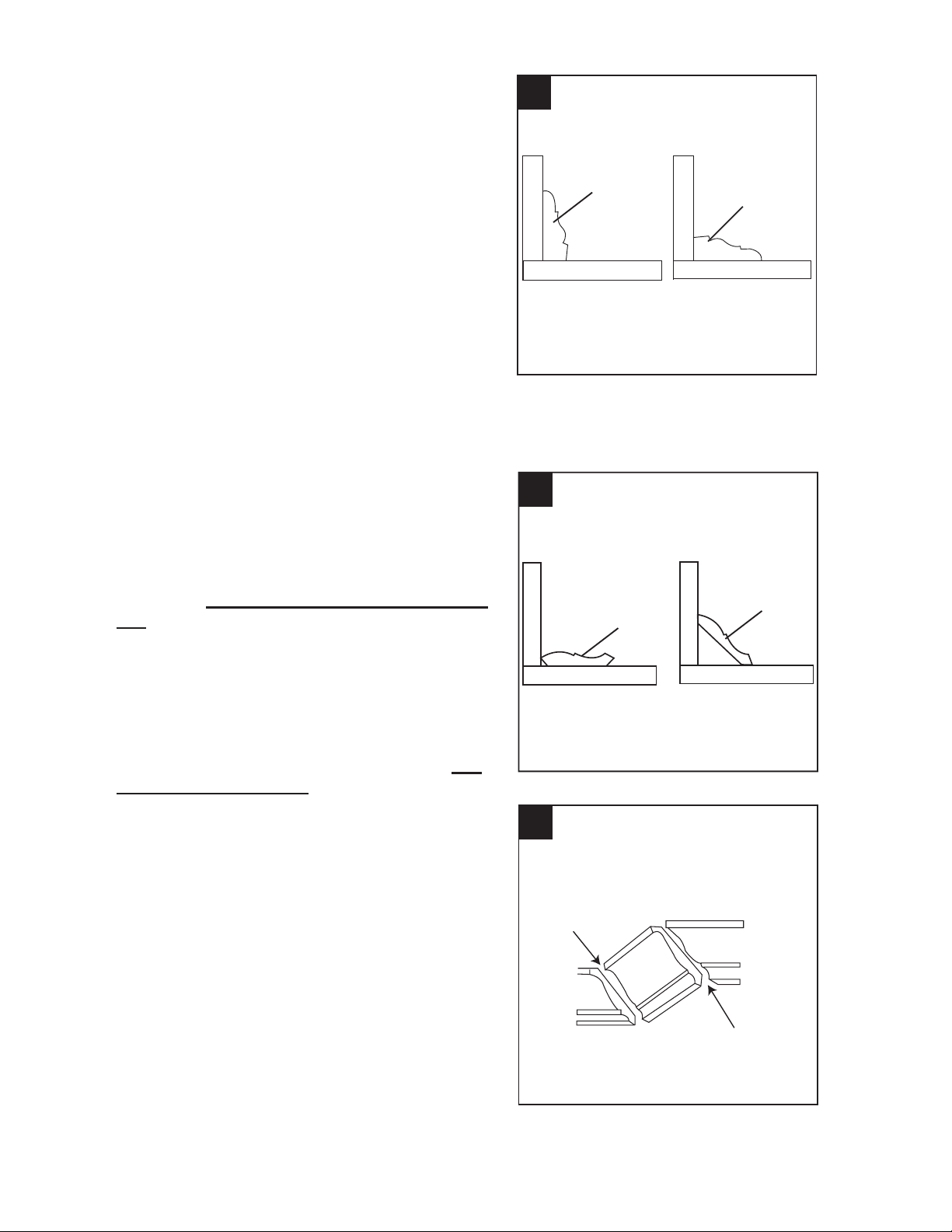
CUTTING BASE MOLDING (FIG. 36)
Base moldings and many other moldings can
be cut on a compound miter saw. The setup of
the saw depends on molding characteristics and
applications, as shown. Perform practice cuts on
scrap material to achieve best results:
ŏ $OZD\VPDNHVXUHPROGLQJVUHVW¿UPO\DJDLQVW
the fence and table. Use hold-down or C-clamps,
whenever possible, and place tape on the area
being clamped to avoid marks.
ŏ Reduce splintering by taping the cut area prior to
making cut. Mark cut line directly on the tape.
ŏ Splintering typically happens due to wrong blade
application and thinness of the material.
NOTE: Always perform a dry run cut so you can
determine if the operation being attempted is
possible before power is applied to the saw.
CUTTING CROWN MOLDING (FIG. 37, 38)
<RXUFRPSRXQGPLWHUVDZLVVXLWHGIRUWKHGLႈFXOW
WDVNRIFXWWLQJFURZQPROGLQJ7R¿WSURSHUO\FURZQ
molding must be compound-mitered with extreme
accuracy. The two surfaces on a piece of crown
PROGLQJWKDW¿WÀDWDJDLQVWWKHFHLOLQJDQGZDOODUHDW
angles that, ZKHQDGGHGWRJHWKHUHTXDOH[DFWO\
90°.
Most crown molding has a top rear angle (the
VHFWLRQWKDW¿WVÀDWDJDLQVWWKHFHLOLQJRIDQGD
ERWWRPUHDUDQJOHWKHVHFWLRQWKDW¿WVÀDWDJDLQVW
the wall) of 38°.
In order to accurately cut crown molding for a 90°
inside or outside corner, lay the molding with its
EURDGEDFNVXUIDFHÀDWRQWKHVDZWDEOH
When setting the bevel and miter angles for
compound miters, remember the settings are
interdependent; changing one changes the other,
as well.
36
F
e
n
c
e
Miter at 45°, bevel at 0°
Miter saw table
Workpiece
Miter at 0°, bevel at 45°
F
e
n
c
e
Miter saw table
Workpiece
37
38
F
e
n
c
e
Miter saw table
Workpiece
Miter saw table
Workpiece
F
e
n
c
e
Settings for standard crown molding lying
ÀDWRQFRPSRXQGPLWHUVDZWDEOH
Compound cut crown moldings
Inside corner
Outside corner
IR
IL
OL
OR
Bevel/Miter Settings
See next page for settings chart

35
NOTE: The chart below references a compound cut for crown molding ONLY WHEN THE
ANGLE BETWEEN THE WALLS EQUALS 90°.
Bevel/Miter Settings
KEY
BEVEL
SETTING
MITER
SETTING
TYPE OF CUT
Inside corner - Left side
IL 33.9° 31.6° Right
1. Position top of molding against fence.
2. Miter table set at RIGHT 31.6°.
/()7VLGHLV¿QLVKHGSLHFH
Inside corner - Right side
IR 33.9° 31.6° Left
1. Position bottom of molding against fence.
2. Miter table set at LEFT 31.6°.
/()7VLGHLV¿QLVKHGSLHFH
Outside corner - Left side
OL 33.9° 31.6° Left
1. Position bottom of molding against fence.
2. Miter table set at LEFT 31.6°.
5,*+7VLGHLV¿QLVKHGSLHFH
Outside corner - Right side
OR 33.9° 31.6° Right
1. Position top of molding against fence.
2. Miter table set at RIGHT 31.6°.
5,*+7VLGHLV¿QLVKHGSLHFH

36
52/38° Crown Molding 45/45° Crown Molding
Angle Between
Walls
Miter
Setting
Bevel
Setting
Miter
Setting
Bevel
Setting
67 42.93 41.08 46.89 36.13
68 42.39 40.79 46.35 35.89
69 41.85 40.50 45.81 35.64
70 41.32 40.20 45.28 35.40
71 40.79 39.90 44.75 35.15
72 40.28 39.61 44.22 34.89
73 39.76 39.30 43.70 34.64
74 39.25 39.00 43.18 35.38
75 38.74 38.69 42.66 34.12
76 38.24 38.39 42.15 33.86
77 37.74 38.08 41.64 33.60
78 37.24 37.76 41.13 33.33
79 36.75 37.45 40.62 33.07
80 36.27 37.13 40.12 32.80
81 35.79 36.81 39.62 32.53
82 35.31 36.49 39.13 32.25
83 34.83 36.17 38.63 31.98
84 34.36 35.85 38.14 31.70
85 33.90 35.52 37.66 31.42
86 33.43 35.19 37.17 31.34
87 32.97 34.86 36.69 30.86
88 32.52 34.53 36.21 30.57
89 32.07 34.20 35.74 30.29
90 31.62 33.86 35.26 30.00
91 31.17 33.53 34.79 29.71
92 30.73 33.19 34.33 29.42
93 30.30 32.86 33.86 29.13
94 29.86 32.51 33.40 28.83
95 29.43 32.17 32.94 28.54
96 29.00 31.82 32.48 28.24
97 28.58 31.48 32.02 27.94
98 28.16 31.13 31.58 27.64
99 27.74 30.78 31.13 27.34
100 27.32 30.43 30.68 27.03
101 26.91 30.08 30.24 26.73
102 26.50 29.73 29.80 26.42
103 26.09 29.38 29.36 26.12
104 25.69 29.02 28.92 25.81
105 25.29 28.67 28.48 25.50
106 24.89 28.31 28.05 25.19
107 24.49 27.96 27.62 24.87
108 24.10 27.59 27.19 24.56
109 23.71 27.23 26.77 24.24
110 23.32 26.87 26.34 23.93
111 22.93 26.51 25.92 23.61
112 22.55 26.15 25.50 23.29
113 22.17 25.78 25.08 22.97
114 21.79 25.42 24.66 22.66
115 21.42 25.05 24.25 22.33
116 21.04 24.68 23.84 22.01
117 20.67 24.31 23.43 21.68
118 20.30 23.94 23.02 21.36
119 19.93 23.57 22.61 21.03
120 19.57 23.20 22.21 20.70
121 19.20 22.83 21.80 20.38
122 18.84 22.46 21.40 20.05
123 18.48 22.09 21.00 19.72
52/38° Crown Molding 45/45° Crown Molding
Angle Between
Walls
Miter
Setting
Bevel
Setting
Miter
Setting
Bevel
Setting
124 18.13 21.71 20.61 19.39
125 17.77 21.34 20.21 19.06
126 17.42 20.96 19.81 18.72
127 17.06 20.59 19.42 18.39
128 16.71 20.21 19.03 18.06
129 16.37 19.83 18.64 17.72
130 16.02 19.45 18.25 17.39
131 15.67 19.07 17.86 17.05
132 15.33 18.69 17.48 16.71
133 14.99 18.31 17.09 16.38
134 14.66 17.93 16.71 16.04
135 14.30 17.55 16.32 15.70
136 13.97 17.17 15.94 15.36
137 13.63 16.79 15.56 15.02
138 13.30 16.40 15.19 14.62
139 12.96 16.02 14.81 14.34
140 12.63 15.64 14.43 14.00
141 12.30 15.25 14.06 13.65
142 11.97 14.87 13.68 13.31
143 11.64 14.48 13.31 12.97
144 11.31 14.09 12.94 12.62
145 10.99 13.71 12.57 12.29
146 10.66 13.32 12.20 11.93
147 10.34 12.93 11.83 11.59
148 10.01 12.54 11.46 11.24
149 9.69 12.16 11.09 10.89
150 9.37 11.77 10.73 10.55
151 9.05 11.38 10.36 10.20
152 8.73 10.99 10.00 9.85
153 8.41 10.60 9.63 9.50
154 8.09 10.21 9.27 9.15
155 7.77 9.82 8.91 8.80
156 7.46 9.43 8.55 8.45
157 7.14 9.04 8.19 8.10
158 6.82 8.65 7.83 7.75
159 6.51 8.26 7.47 7.40
160 6.20 7.86 7.11 7.05
161 5.88 7.47 6.75 6.70
162 5.57 7.08 6.39 6.35
163 5.26 6.69 6.03 6.00
164 4.95 6.30 5.68 5.65
165 4.63 5.90 5.32 5.30
166 4.32 5.51 4.96 4.94
167 4.01 5.12 4.61 4.59
168 3.70 4.72 4.25 4.24
169 3.39 4.33 3.90 3.89
170 3.08 3.94 3.54 3.53
171 2.77 3.54 3.19 3.10
172 2.47 3.15 2.83 2.83
173 2.15 2.75 2.48 2.47
174 1.85 2.36 2.12 2.12
175 1.54 1.97 1.77 1.77
176 1.23 1.58 1.41 1.41
177 0.92 1.18 1.06 1.06
178 0.62 0.79 0.71 0.71
179 0.31 0.39 0.35 0.35
CROWN MOLDING CHART
Compound Miter Saw
Miter and Bevel Angle Settings
Wall to Crown Molding Angle
37
39
CARE AND MAINTENANCE
ŏ
7RDYRLG¿UHRUWR[LFUHDFWLRQQHYHUXVHJDVROLQH
naphtha
, acetone, lacquer thinner or similar
highly volatile solvents to clean the miter saw.
ŏ
To avoid injury from unexpected starting or
electrical shock, unplug the power cord before
working on the saw.
ŏ
For your safety, this saw is double insulated.
7RDYRLGHOHFWULFDOVKRFN¿UHRULQMXU\XVHRQO\
SDUWVLGHQWLFDOWRWKRVHLGHQWL¿HGLQWKHSDUWVOLVW
Reassemble exactly to avoid electrical shock.
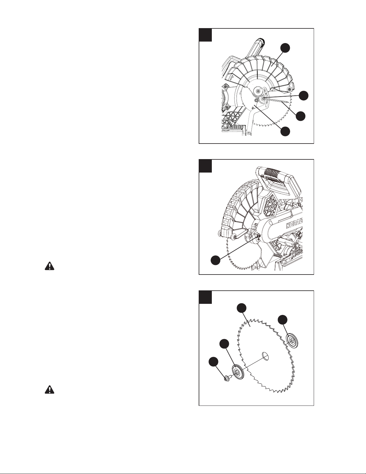
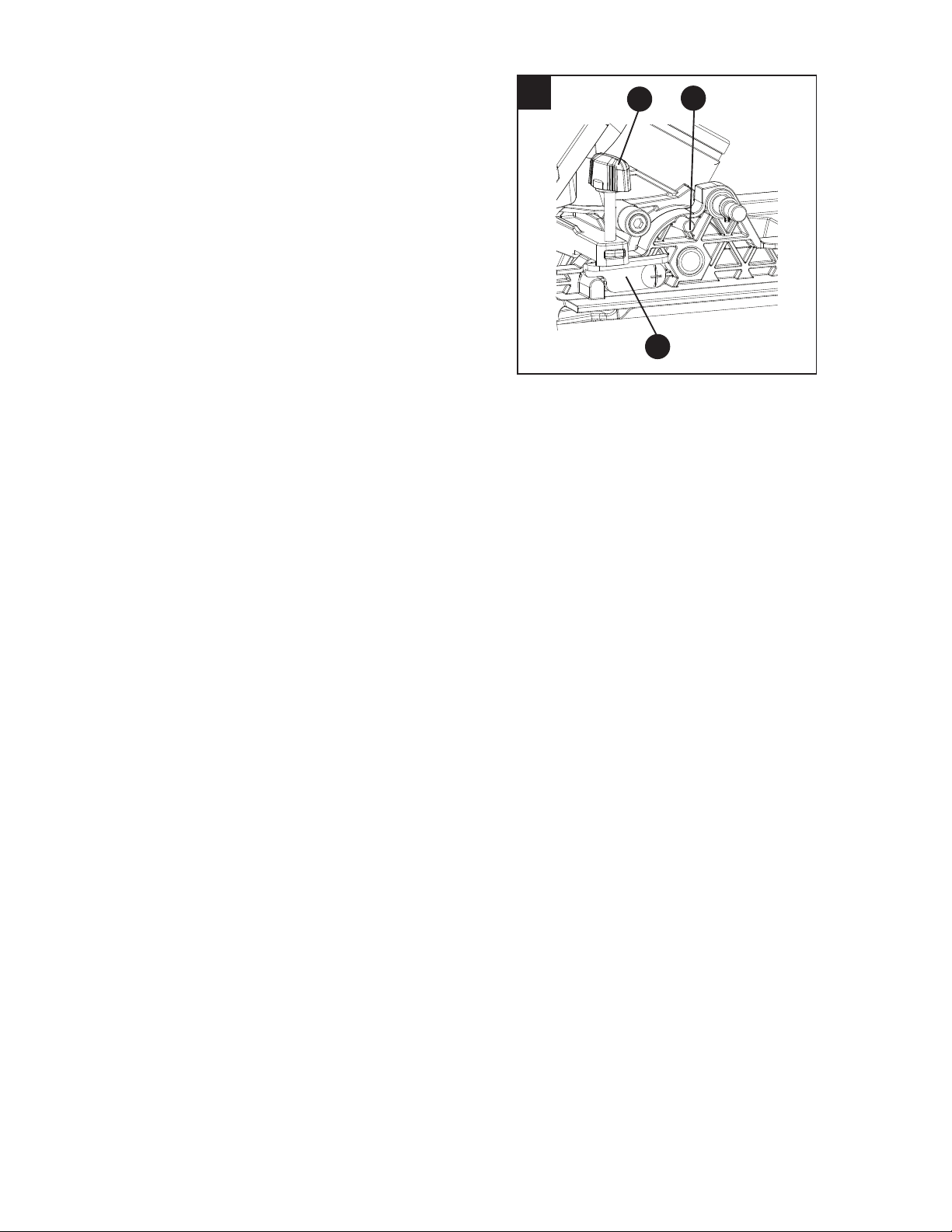
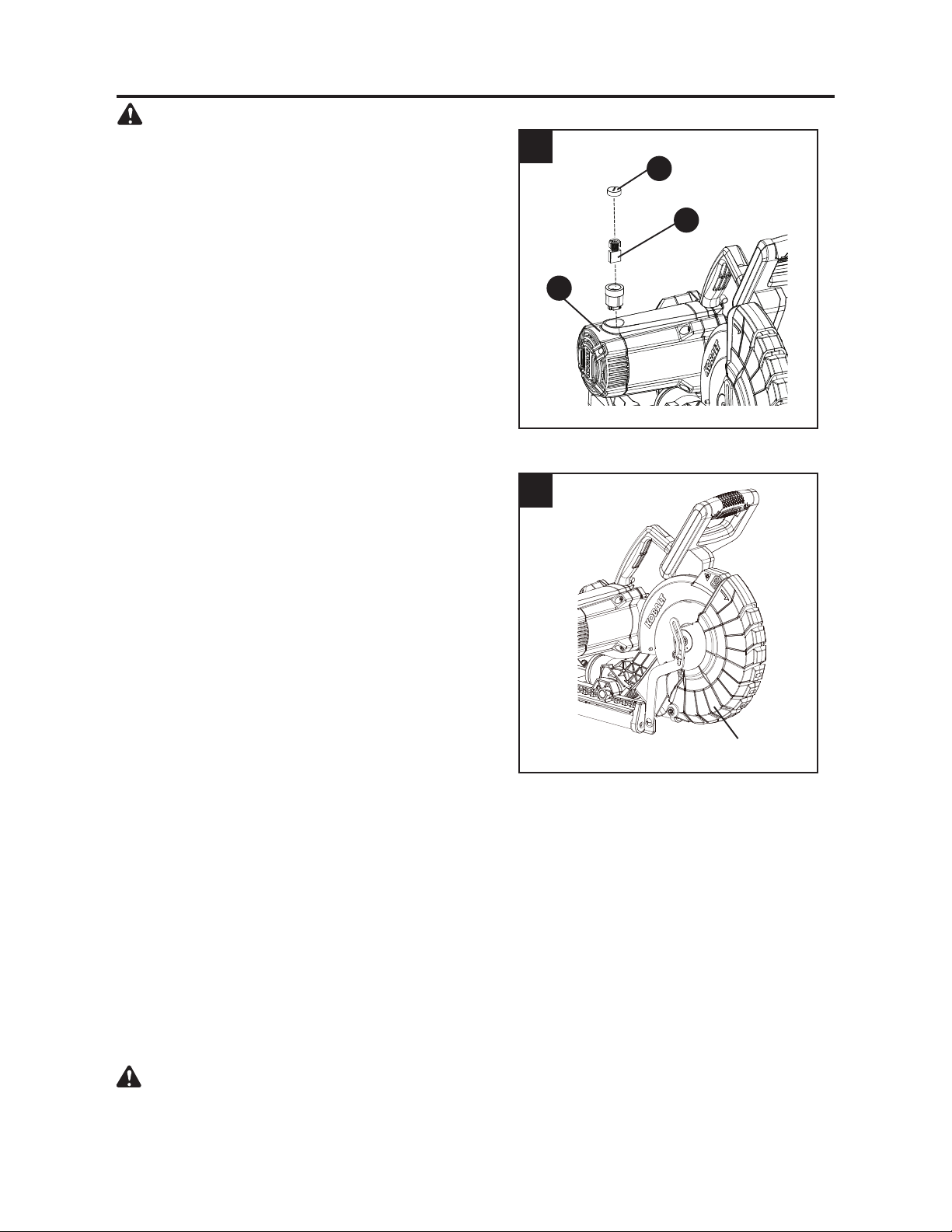
REPLACING CARBON BRUSHES (FIG. 39)
The carbon brushes (Q) furnished will last
approximately 50 hours of running time, or 10,000
ON/OFF cycles. Replace both carbon brushes
when either has less than 1/4 in. length of carbon
remaining, or if the spring or wire is damaged or
EXUQHG7RLQVSHFWRUUHSODFHEUXVKHV¿UVWXQSOXJ
the saw. Remove the black plastic cap (1) on
the side of the motor (R). Carefully remove the
spring-loaded cap. Pull out the brush and replace.
Repeat for the other side. Reverse the procedure
for reassembly. Press the metal part of the carbon
EUXVKLQWRWKHKROHZKHUHWKHFDUERQSDUW¿WV
Tighten the cap snugly but do not overtighten.
NOTE: 7RUHLQVWDOOWKHVDPHEUXVKHV¿UVWPDNH
sure the brushes go back in the way they came out.
This will avoid a break-in period that reduces motor
performance and increases wear.
Q
1
R
40
Lower blade guard
LOWER BLADE GUARD (FIG. 40)
Do not use the saw without the lower blade guard. The lower blade guard is attached to the
saw for your protection. Should the lower guard become damaged, do not use the saw until the
damaged guard has been replaced. Check regularly to make sure the lower guard is working
properly. Clean the lower guard of any dust or buildup with a damp cloth.
ŏ
Do not use solvents on the guard. They could make the plastic cloudy and brittle.
ŏ
When cleaning the lower guard, unplug the saw to avoid unexpected start-up.
SAWDUST
3HULRGLFDOO\VDZGXVWZLOODFFXPXODWHXQGHUWKHZRUNWDEOHDQGEDVH7KLVFRXOGFDXVHGLႈFXOW\LQ
the movement of the worktable when setting up a miter cut. Frequently blow out or vacuum up the
sawdust.
If blowing sawdust, wear proper eye protection to keep debris from blowing into eyes.
WARNING
CAUTION
38
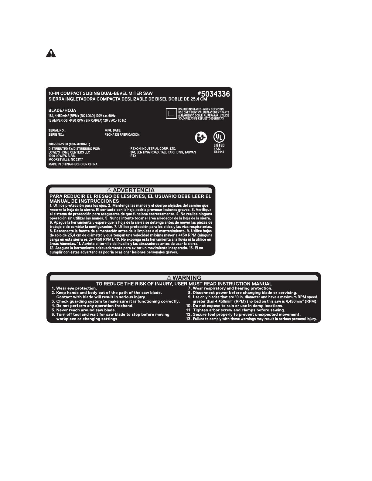
FREE WARNING LABEL REPLACEMENT: If your warning labels become illegible or are missing,
call 888-356-2258
for a free replacement.
DO NOT replace the power cord. If you have any problem or questions concerning the power
cord, call the Customer Service Department at 888-356-2258.
WARNING

39
To avoid injury from accidental starting, always ensure that the switch is in the OFF position and
unplug the tool before moving, replacing the blade or making adjustments.
TROUBLESHOOTING - MOTOR
PROBLEM PROBLEM CAUSE CORRECTIVE ACTION
Brake does not
stop the blade
within 5 seconds.
1. Motor brushes not sealed or lightly
sticking.
2. Motor brake overheated from use
of defective or wrong size blade or
rapid ON/OFF cycling.
3. Arbor bolt loosened.
4. Other.
1. Inspect, clean and/or replace
brushes. See MAINTENANCE
section.
2. Use the recommended blade.
Allow to cool down.
3. Retighten arbor bolt.
4. Contact customer service.
Motor does not
start.
1. Blown fuse.
2. Worn brush.
3. Other.
1. Use and check the 20A time-delay
fuse or the circuit breaker.
2. See MAINTENANCE section.
3. Contact customer service.
Excessive brush
spark when the
switch is released.
1. Brush worn. 1. Replace brushes.
TROUBLESHOOTING – SAW OPERATION
PROBLEM PROBLEM CAUSE CORRECTIVE ACTION
Blade hits table. 1. Misalignment. 1. See ADJUSTMENT section.
Angle of cut not
accurate. Cannot
adjust miter.
1. Miter table locked.
2. Sawdust under table.
1. Push positive stop locking lever
down and rotate table. See
OPERATION section.
2. Vacuum or blow out dust. WEAR
EYE PROTECTION.
Cutting arm
wobbles.
1. Loose pivot points. 1. See ADJUSTMENT section.
Cutting arm will not
fully raise or blade
guard will not fully
close.
1. Part failure.
2. Pivot spring not replaced properly
after service.
3. Sawdust build-up.
1. Contact customer service.
2. Contact customer service.
3. See CARE AND MAINTENANCE
section.
Blade binds, jams,
burns wood.
1. Improper operation.
2. Dull blade.
3. Improper blade size.
4. Warped blade.
1. See BASIC SAW OPERATIONS
section.
2. Replace or sharpen blade.
3. Replace with 10 in. diameter blade.
4. Replace blade.
Saw vibrates or
shakes.
1. Saw blade not round.
2. Saw blade damaged.
3. Saw blade loose.
4. Saw blade warped.
1. Replace blade.
2. Replace blade.
3. Tighten arbor bolt.
4. Replace blade.
TROUBLESHOOTING
WARNING
40
REPLACEMENT PARTS LIST
For replacement parts, call our customer service department at 888-3KOBALT (888-356-2258),
8 a.m. - 8 p.m., EST, Monday - Sunday. You could also contact us at [email protected].
PART DESCRIPTION PART #
B Hold-down clamp 3VMS
C Dust bag 3YSA
D Bevel lock handle assembly 3X3B
E Blade wrench 3VJN
H
Table inserts (set of 2)
3TSA (left) /3TS6 (right)
I
Miter lock handle
47L7
O
Sliding fences (set of 2)
3ZMK (left) / 3ZML (right)
Q Carbon brushes (set of 2) 0QQT
S
Carrying handle
3VKY
Y
Fence base
3TRM
GG Manual 508A
HH
Extension locks assembly
(set of 2)
51R6 (left) / 51R7
(right)
II
Extension wings assembly (set of 2)
51R4 (left) / 51R5
(right)
JJ
Blade guard assembly
51R3
H
Y
D ECB
DISTRIBUTED BY:
Lowe's Home Centers LLC
1000 Lowe's Blvd., Mooresville, NC 28117
GG HH
Q
S
O
I
II JJ

41
PAGE INTENTIONALLY LEFT BLANK

42
PAGE INTENTIONALLY LEFT BLANK

43
PAGE INTENTIONALLY LEFT BLANK

44
WARRANTY
7KHPDQXIDFWXUHUZLOORႇHUUHSODFHPHQWSDUWVIRUWKLVSURGXFWZKLFKXQGHUQRUPDOXVDJHKDYH
proven to be defective in their manufacture or workmanship for a period of THREE (3) years
from the date of initial retail purchase. This warranty is valid only to the original purchaser. This
warranty is not transferable and does not cover any parts that have been subjected to misuse,
abuse, alteration, overload, accident or normal wear of moving parts. Tools that have been sold
“as is,” sold reconditioned or used as rental equipment are not covered.
Warranty replacement parts can be obtained by contacting the manufacturer at 888-3KOBALT.
Only the manufacturer is authorized to perform warranty service on this product. This warranty
does not apply to accessories or damage caused where repairs have been made or attempted by
others.
The manufacturer is not responsible for direct, indirect, incidental or consequential damages.
Some states do not allow limitations on how long an implied warranty lasts and/or do not allow the
exclusion or limitation of incidental damages, so the above limitations may not apply to you. This
ZDUUDQW\JLYHV\RXVSHFL¿FOHJDOULJKWVDQG\RXPD\DOVRKDYHRWKHUULJKWVZKLFKYDU\IURPVWDWH
to state.
The manufacturer makes no warranties, representations or promises as to the quality of its power
WRROVRWKHUWKDQWKRVHVSHFL¿FDOO\VWDWHGLQWKLVZDUUDQW\
WARRANTY VOID IF PRODUCT USED FOR COMMERICAL PURPOSES
For replacement parts, call our customer service department at 888-3KOBALT (888-356-2258).
Printed in China
Manufacturer
REXON INDUSTRIAL CORP., LTD.
261, Jen Hwa Road, Tali,
Taichung, Taiwan