Remove the tool from the package and examine it carefully. Do not discard the carton or any packaging material until all parts have been examined.
If any part of the tool is missing or damaged, do not attach the battery pack or use the tool until the part has been repaired or replaced. Failure to heed this warning could result in serious injury
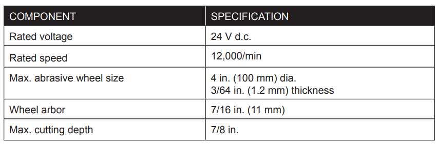
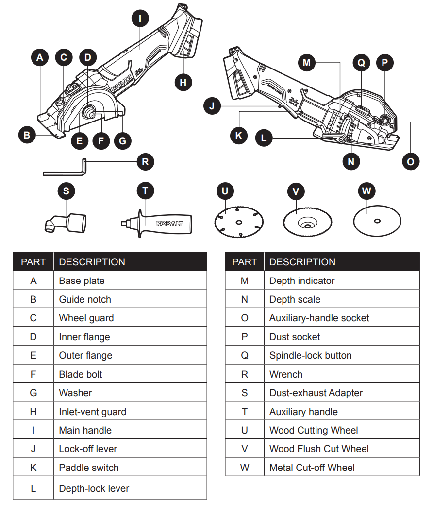
OPERATING INSTRUCTIONS
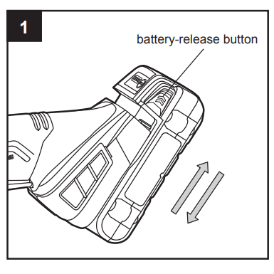
1. To Attach Battery Pack
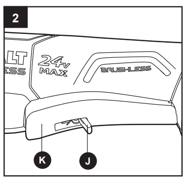
Ensure that the paddle switch (K) is in the OFF position.
Align the raised portion on the battery pack with the grooves on the bottom of the tool, then slide the battery pack onto the tool, as shown.
Make sure that the latches on the battery pack snap into place and the battery pack is secured to the tool before beginning operation.
NOTICE: When placing the battery pack on the tool, be sure that the raised rib on battery pack aligns with the groove on the tool and the latches snap into place properly. Improper assembly of the battery pack can cause damage to internal components.
To Detach Battery Pack
Ensure that the paddle switch (K) is in the OFF position.
Press the battery-release buttons to release the battery pack.
Pull forward on the battery pack to remove it from the tool.
WARNING
To reduce the risk of injury, always remove the battery pack before making any adjustments or changing accessories.
2. Paddle Switch Operation
The saw is equipped with a paddle switch (K) to turn the tool on and off.
To turn the tool ON, push the lock-off lever (J) forward, then squeeze the paddle switch.
To turn it OFF, release the paddle switch and allow it to return to the OFF position. Make sure that the tool comes to a complete stop before laying the tool down.
NOTICE: If the battery is inserted when the tool switch is in the “ON” position, the tool will not run. Turn the tool off, then turn it on to begin work.
WARNING
To reduce the risk of injury, hold the handle and auxiliary handle firmly with both hands to provide a secure support during operation.
To reduce the risk of injury, wear safety goggles or glasses with side shields during power tool operation.
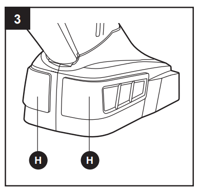
3. Inlet-Vent Guard
Using the inlet-vent guards (H) will improve the performance and extend the life of the tool.
To attach the guard, snap the guard onto the tool’s foot.
To remove the guard, insert a flathead screwdriver (not included) into the notch at the top of the guard, then pry the guard away from the tool.
Clean the inlet-vent guard
To clean the guard, tap it against a hard surface or blow it clean with compressed air.
WARNING
To reduce the risk of injury, wear safety goggles or glasses with side shields when cleaning with compressed air.
To reduce the risk of injury, always remove the battery pack before any adjusting or accessory changing.
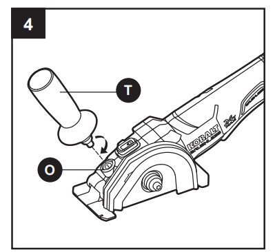
4. Auxiliary Handle
This saw is equipped with an auxiliary handle (T).
The handle can be installed in the auxiliary-handle socket (O).
To install the auxiliary handle, thread the auxiliary handle into the auxiliary-handle socket and tighten the handle securely by turning it clockwise.
To remove the auxiliary handle, loosen the auxiliary handle by turning the handle counterclockwise and remove it from the tool.
WARNING
For safety and ease of operation, securely tighten the auxiliary handle by turning the handle clockwise before use.
To reduce the risk of injury, always remove battery pack before any adjusting or accessory changing.
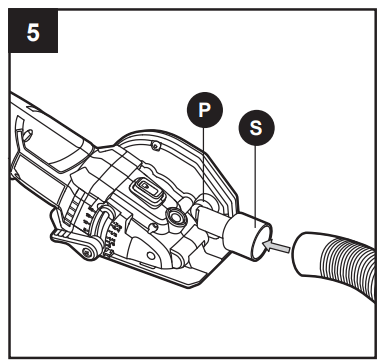
5. Dust-Exhaust Adapter
This versatile saw is equipped with a dust-exhaust
Adapter (S) to collect the dust created during operation. The dust-exhaust Adapter can be connected to a 1-1/4 in. diameter vacuum hose to help keep the work area clean.
To attach a 1-1/4 in. vacuum hose
Remove the battery from the tool.
Insert the dust-exhaust Adapter into the dust socket (P) in the saw as far as possible.
Attach a 1-1/4 in. vacuum hose (not included) to the dust-exhaust Adapter.
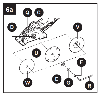
6. Installing/Removing Accessories
DANGER
This product is only designed for grinding, polishing and cutting-off. Use for any other purpose is not recommended and may result in serious injury.
WARNING
Only use accessories with a Maximum Safe Operating Speed rated at least equal to the maximum speed marked on the tool.
Only use accessories that comply with the correct size marked on the tool and described in the Product Specification chart located on page 2 of the manual.
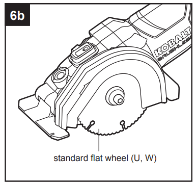
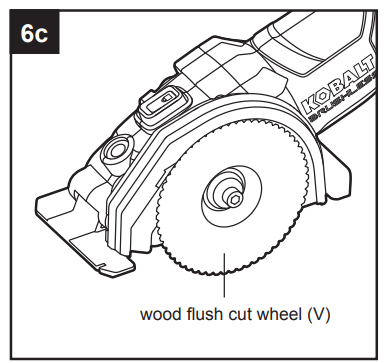
The multi-purpose saw can be used with the cutting wheel oriented in 2 different positions. One position uses a standard flat wheel for typical straight and plunge cuts (Fig. 6b). The second wheel position may be used for making flush cuts along flooring or against walls and for surface preparation. (Fig. 6c).
To Install a Wheel
Remove the battery pack.
Depress and hold the spindle-lock button (Q) and remove the blade bolt (F) by turning it clockwise with the wrench (R).
Remove the washer (G) and the outer flange (E). WARNING
If the inner flange (D) has been removed, replace it before placing the blade on the spindle. Failure to do so could result in serious personal injury.
Fit the wheel (U, V, or W) inside the guard and onto the spindle.
Replace the outer flange with the protruding section facing outward.
Depress and hold the spindle-lock button and replace the blade bolt.
Tighten the bolt securely by using the wrench to turn it counterclockwise.
To Remove Wheel
Remove the battery pack.
Depress and hold the spindle-lock button (Q) and remove the blade bolt (F) by turning it clockwise with the wrench (R).
Remove the washer (G) and the outer flange and remove the wheel.
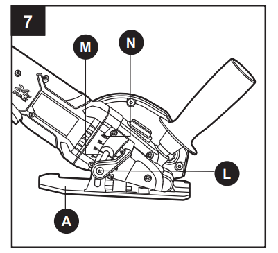
7. Adjusting the Cutting Depth
WARNING
Always maintain the correct cutting-depth setting.
The correct cutting-depth setting for all cuts should not exceed the thickness of the material being cut by more than 1/4 in. (6.5 mm). Greater cutting depth will increase the chance of dangerous kickback and will cause the cut to be rough.
Remove the battery pack from the saw.
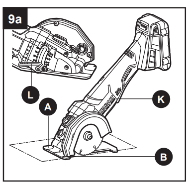
Raise the depth-lock lever (L) to release it.
Hold the tip of the base plate (A) tip against the workpiece and raise or lower the saw until the indicator mark (M) on the saw aligns with the desired depth on the depth scale (N).
Lower depth-lock lever to lock the selected cutting depth.
8. General Cutting
WARNING
To make cutting easier and safer, always maintain proper control of the saw. Loss of control could cause an accident resulting in serious injury. Never force the tool. Use a light and continuous pressure.
DANGER
Always make sure that the wheel has come to complete stop before setting the tool down. A spinning blade contacting a hard surface will cause the tool to walk back and may injure you.
WARNING
Always wear safety goggles or safety glasses with side shields during power tool operation. If the operation is dusty, also wear a dust mask.
The cut-off wheel (W) is suited for small cut-off operations only. Using the cut-off wheel in a grinding operation will cause the wheel to crack and break, resulting in serious personal injury.
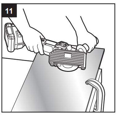
To make the safest and best possible cut, follow these directions:
Clamp the workpiece securely so that the workpiece will not move during the cut. If the workpiece is too small to clamp it securely, do not use this tool to cut it.
Support the workpiece near the cut.
Support the workpiece so that the cut is always to the operator’s side and not directly in line with the operator’s body
Hold the tool firmly while cutting and always be ready and able to manage the cut. Use the auxiliary handle (T) if needed.
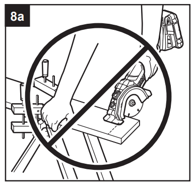
Avoid placing your hand on the workpiece while making a cut. (Fig. 8a).
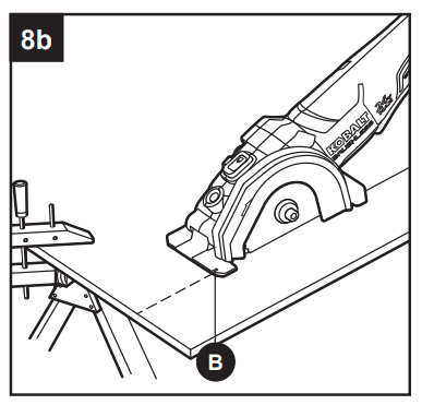
Always place the saw on the portion of the workpiece that is supported, not on the “cut off” piece (Fig. 8b).
Draw a guideline along the desired cutting line before beginning the cut.
The guide notch (B) will only give an approximate line of cut when used with standard wheels (such as parts U and W). Make sample cuts in scrap lumber to verify the actual line of cut.
Avoid jamming, twisting or pinching the wheel within the workpiece or otherwise applying excessive side pressure to the wheel.
NOTICE: If the battery is inserted when the tool switch is in the “ON” position, the tool will not run. Turn the tool off, then turn it on to begin work.
Cutting tile
Score the tile first along your cut line, making multiple passes to progressively cut through the tile.
For cuts that extend to the edge of a tile, cut all the way through edge(s) along your cut line
This tool does not use wheels designed for face-grinding. If your cut requires a smooth, finished edge, use an appropriate tile finishing tool to refine the tile edge.
Cutting metal
It is possible to perform limited cutting on small stock such as copper pipe, conduit, rebar, threaded rod, coated wire shelving, aluminum sheet with this tool.
Work with a moderate rate of feed, adapted to the material being cut. Do not exert side pressure onto the cutting wheel, tilt, or wiggle the tool.
When cutting profiles and square bar stock, it is best to start at the smallest cross section.
Always follow precautions for kickback.
Do not apply side pressure to the cutting wheel to reduce wheel speed.
The tool should always be used so that sparks are directed away from user.
After each use, remove the wheel and clean the inside and outside of the guard with compressed air. Preventive maintenance of the guard will reduce the possibility of an accident.
9. Plunge Cutting
Your saw is ideal for plunge cutting directly into a workpiece, such as walls or floors.
WARNING
Do not plunge cut into metal surfaces or tile.
Draw a guideline along the desired cutting line before beginning the cut.
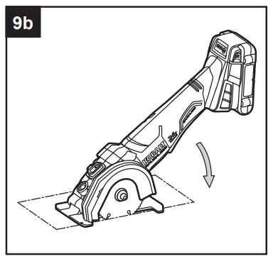
Loosen the depth-lock lever (L) so that the base plate (A) releases and goes to the zerodepth setting. Leave the depth-lock lever loose during this cut.
Rest the base plate of the tool on the workpiece and align the guide notch (B) with the cut line.
While holding the tool firmly, make sure that the wheel does not touch the workpiece.
Push forward the lock-off lever (J) and press the paddle switch (K) to start the saw. e. Allow the wheel to come to full speed, then slowly lower the wheel into the workpiece and make the cut.
Release the paddle switch and allow the wheel to come to a complete stop. g. Lift the tool from the workpiece.
Repeat steps b-g as required to complete the cuts.
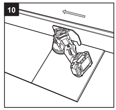
10. Flush Cutting
First, consider the desired height of the flush cut. For flooring installation, take into account the thickness of your flooring adhesive, the flooring itself, and any underlayment or other material that will add to the thickness of the finished floor.
Install the wood flush cut wheel (V) on the tool as described in “Installing/Removing Accessories”.
Adjust the depth of the blade to the desired depth setting.
Turn the tool on its side so that the wheel guard (C) rests against the flooring.
Firmly grip the tool, using the auxiliary handle (T) if needed. Turn the tool on and allow it to come to full speed before allowing the blade to enter the workpiece.
Complete the cut, release the paddle switch and allow the wheel to come to a complete stop.
Lift the tool from the workpiece.
11. Surface Preparation (optional)
WARNING
To reduce the risk of injury, read all safety warnings and all instructions in the use, care, and protection of wheels.
Always wear safety goggles or safety glasses with side shields during power tool operation. If the operation is dusty, also wear a dust mask.
Check the surface prep wheels (not included) before application. Discard wheels that have been dropped, bumped, subjected to extreme changes in temperature, or come into contact with solvents or wetness.
Before beginning a period of work, test the tool by letting it spin for one minute before applying it to the workpiece.
Make sure that the workpiece is firmly clamped in place.
Hold the tool securely with both hands.
Start the tool. NOTICE: If the battery is inserted when the tool switch is in the “ON” position, the tool will not run. Turn the tool off, then turn it on to begin work.
Allow the accessory to reach full speed before beginning work.
For a uniform finish, hold tool at an angle of approximatley 10° to 15° to the workpiece and apply constant pressure. Too great an angle causes concentrated pressure on small areas, which may gouge or burn the work surface.
Control the pressure and surface contact between accessory and workpiece. WARNING
Do not apply eSxcessive pressure. Too much pressure will cause the tool to overload and may cause personal injury.
When finished, turn off the tool and make sure that it comes to a complete stop before laying it down.
CARE AND MAINTENANCE
All maintenance should only be carried out by a qualified service technician.
Care of Wheels
The wheels should be stored in an organized way so that wheels can be removed without disturbing or damaging other wheels.
Cleaning
Before cleaning or performing any maintenance, remove battery from the tool. For safe and proper operation, always keep the tool and its ventilation slots clean.
Always use only a soft, dry cloth to clean your saw; never use detergent or alcohol.
TROUBLESHOOTING
WARNING
Make sure that the paddle switch (K) is in the “OFF” position and detach the battery pack from the tool before performing troubleshooting procedures.
PROBLEM
POSSIBLE CAUSE
CORRECTIVE ACTION
The tool does not work.
1. Battery capacity is low
1. Charge the battery pack.
2. Battery is overheating.
2. Release the switch, wait for the battery to cool down, then start the tool again.
Wheels cannot be installed.
Wheel is the wrong size.
Refer to specification chart for proper wheel size.
Auxiliary handle cannot be installed.
There is dust in the auxiliary handle socket.
Clean and clear the socket.
Motor overheating.
Cooling vents are obstructed.
Clean and clear vents. Do not cover vents with hand during operation.

 All maintenance should only be carried out by a qualified service technician.