Loading ...
Loading ...
Loading ...
22
INSTALLATION INSTRUCTIONS
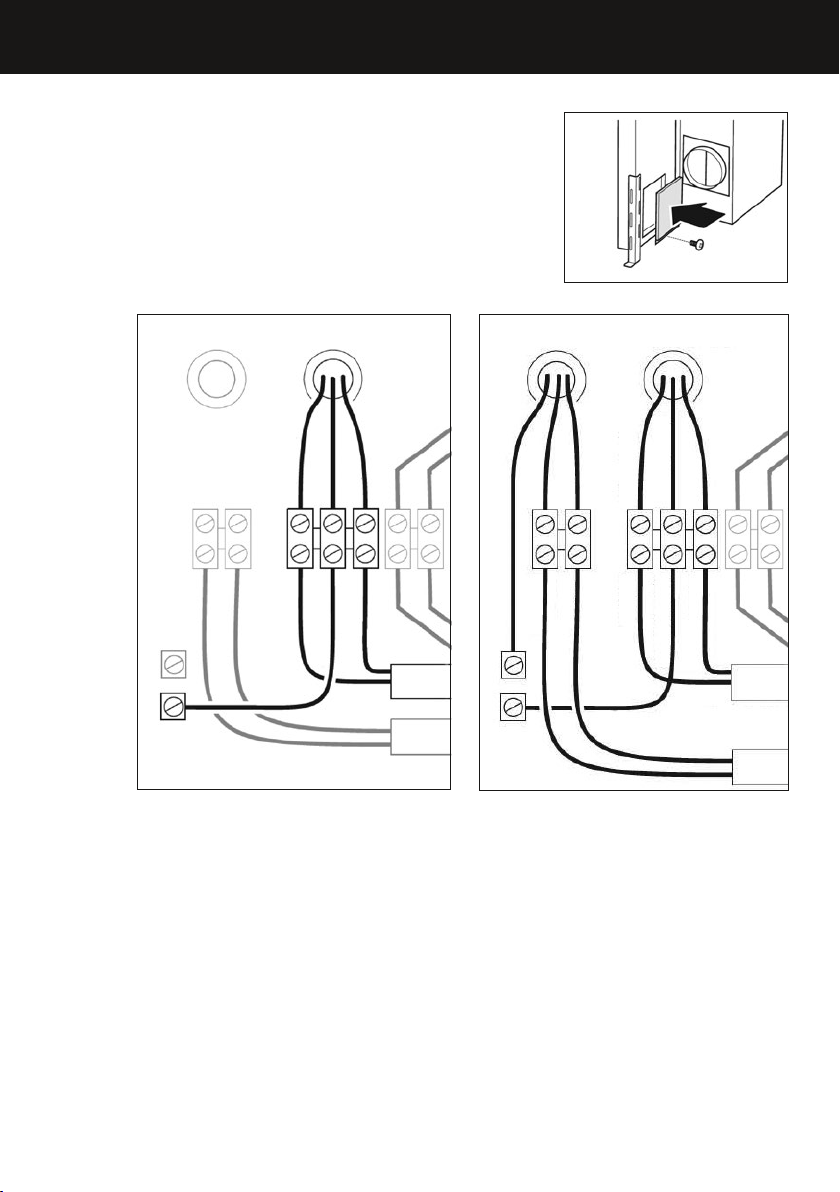
Downdraft unit internal blower electrical connection
●
Connect (L1/live) wire from the power supply
cable into the right terminal Fig.19.
●
Connect the green (ground) wire from the power
supply cable into the middle terminal Fig.19.
●
Connect the (neutral) wire from the power supply
cable into the left terminal Fig.19.
●
Ensure that the terminal screws are tightly
holding all wires in place.
●
Replace the cover of the terminal box Fig.18.
Downdraft unit remote blower electrical connection
●
Connect the power supply cable into the box as described in the ‘Downdraft unit
internal blower electrical connection’ section (above).
●
To use a remote blower, install a control cable between the downdraft unit and
the remote blower. See the ‘Remote blower electrical connection’ on next page.
●
Additional knock outs should be used for the remote blower wiring.
●
Install a suitable UL listed strain relief or conduit fitting (not included) into the
knock out.
●
Connect the remote blower wiring into the downdraft unit: N (neutral) into the
right terminal, L1 (live) into the left terminal and the green (ground) wire goes
into the ground terminal Fig.20.
●
Ensure that the terminal screws are tightly holding all wires in place.
●
The remote blower will be connected to the additional control cable
●
Replace the cover of the terminal box Fig.18.
Fig.18
Downdraft wiring
BROWN L1 (live)
GREEN -YELLOW
LIGHT BLUE N (neutral)
GND (ground)
Home power
supply cable
Ground Screws
BROWN
BLUE
Fig.19
Internal
wiring
BLUE
BROWN
WHITE
BLACK
Downdraft wiring
BROWN L1 (live)
GREEN -YELLOW
GREEN -YELLOW GND (ground)
Home power
supply cable
Remote blower
control cable
Ground Screws
L1 (live)BROWN
Fig.20
LIGHT BLUE N (neutral)
N (neutral)BLUE
Internal
wiring
WHITE
BLACK
BLUE
BROWN
Loading ...
Loading ...
Loading ...