Loading ...
Loading ...
Loading ...
15
INSTALLATION INSTRUCTIONS
2
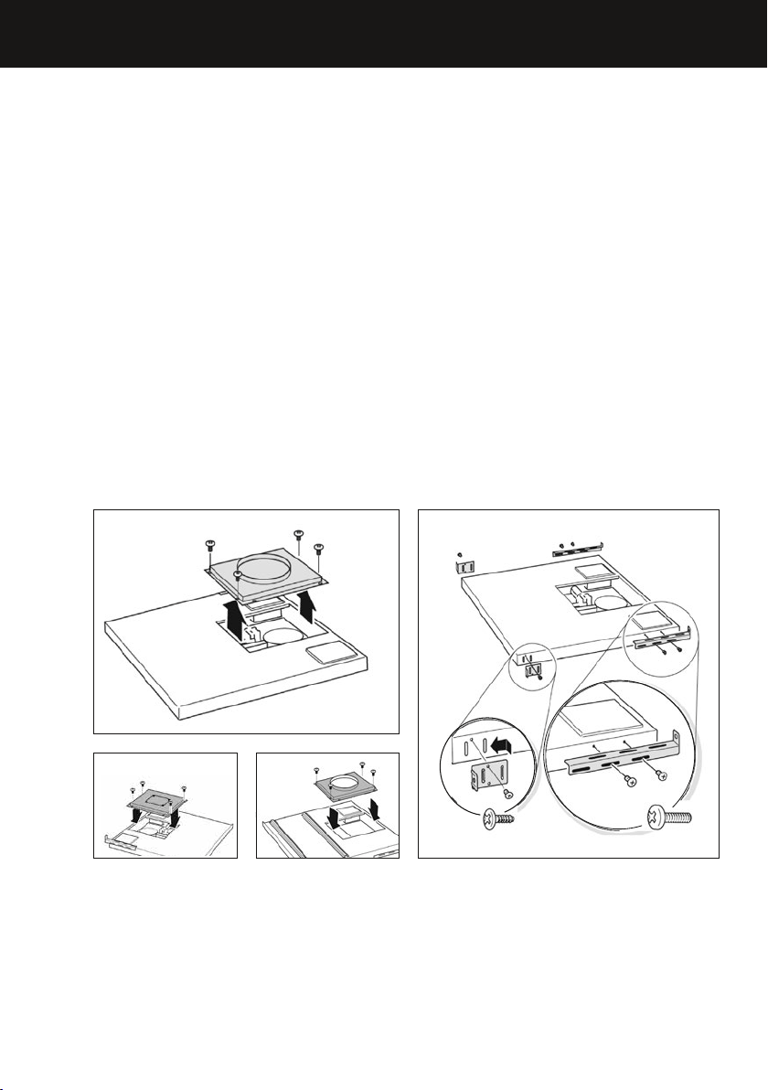
Prepare the downdraft unit for the intended blower
Internal blower
●
Remove the 10” (254 mm) blower connection plate from the front of the downdraft
unit Fig.1.
●
Attach the over counter mounting brackets in place with the two ⁄” (5mm) screws
provided Fig.2.
●
Screw the support leg mounting brackets to the side of the downdraft unit using two
⁄” (8mm) screws each, do not fully tighten the screws. The brackets are different
for the right and the left side. Attach them with mounting clip (A) pointing up.
Remote blower
●
The downdraft unit comes ready for installation with the 10” (254 mm) remote blower
connection plate installed on the front of downdraft unit and the cover plate installed
onto the back.
●
To connect the remote blower to the back of the downdraft unit swap the plates over
(see Fig. 3 and 4).
●
Attach the over counter mounting brackets in place with the two ⁄” (5mm) screws
provided Fig.2.
●
Screw the support leg mounting brackets to the side of the downdraft unit using two
⁄” (8mm) screws each, do not fully tighten the screws. The brackets are different
for the right and the left side. Attach them with mounting clip (A) pointing up.
FRONT
Fig.1
Fig.3
Fig.4
FRONT
2 x
4 x
A
Fig.2
EN
Loading ...
Loading ...
Loading ...