Loading ...
Loading ...
Loading ...
Service Manual: SC750, SC800, SC 750 ST, SC800 ST
Form Number 56043150 Page 87
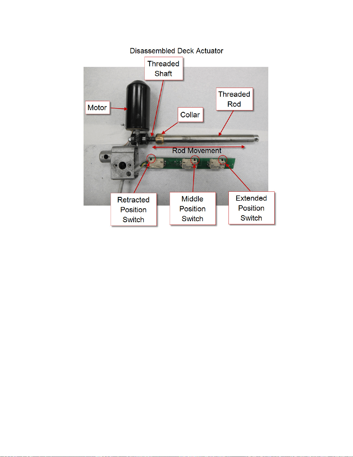
Here is how the circuit works for the actuator. The Main Machine Controller directly drives the brush head actuator mo-
tor. It applies system voltage across the two actuator motor wires to move the motor up. It reverses polarity to move the
motor down. Each posion switch receives a 5 volt feed through a resistor from the controller which returns back to bat-
tery negave on a common wire to connector J2 pin 2. The controller has “internal voltmeters” which monitor the signal
voltage of each switch circuit. When the switch is closed, the voltage signal is approximately 0 volts. When the switch is
open, the voltage is approximately 5 volts.
1. Deck up - Retracted Posion switch = 5v (Other two switches = 0v)
2. Normal Scrub mode - Middle Posion switch = 5v (Other two switches = 0v)
3. Extreme Scrub mode is not used on Cylindrical Deck
Note: The actuator “extended” posion switch circuit is unique because it is also used as a communicaon line between
the Main Machine Controller and the baery charger. The addion of the baery charger on the circuit drops the 5v that
is normally seen when the switch is open to approximately 3 volts. This is normal.
When the key is turned o, if the brush head is down, the Main Machine Controller will raise the brush head to the full
“up” posion. When the operator requests the scrub mode, the controller drives the actuator down unl it sees the
Middle Posion switch open (5v). When the operator turns o the scrub funcon, the controller drives the actuator mo-
tor up unl it sees the Retracted Posion switch open again (5v). If more than one posion switch is open (5v) at a me,
the controller does not know which one to believe. It realizes there must be a problem and will not move the actuator.
Loading ...
Loading ...
Loading ...