Home
Bookmarks
Home
Nilfisk
Nilfisk SC750 User Manual
Page 145
Nilfisk SC750 Heavy-Duty Cleaning
User Manual - Page 145
For SC750.
PDF File Manual
,
164 pages
,
Download pdf file
General Information
Service Manual Purpose and Application
Other Reference Manuals
Conventions
Transporting the Machine
Towing
Cautions and Warnings
Symbols
General Safety Instructions
General Machine Description
Nameplate
Know Your Machine
Control Panel â SC750 and SC800 (Membrane Switch Control Panel)
Control Panel â SC750 ST and SC800 ST (Toggle Switch Control Panel)
Machine Specifications â SC750 and SC750 ST
Machine Specifications â SC800 and SC800 ST
Machine Maintenance
Lubricating the Machine
Chassis System
Functional Description
Control system
Functional Description
Component Locations
Troubleshooting
Fault Codes
Fault Code Table
Service Test Mode
Programming Options âSC750 ST and SC800 ST Models (control panel with rocker switches)
Programming Options â SC750 and SC800 models (Control Panel with membrane switches)
Removal and Installation
Main Machine Controller SC750 ST and SC800 ST Models (Early Build)
Main Machine Controller SC750 ST and SC800 ST Models (Later Build)
Main Machine Controller SC750 and SC800 Models (Early Build)
Main Machine Controller SC750 and SC800 Models (Later build)
Rocker Switches - ST Models
Specifications
Shop Measurements â Main Machine Controller
Electrical System
Functional Description
General
On-board Battery Charger
Delta-Q IC650 Battery Charging Profile Table
Electrical Panel Components
Maintenance and Adjustments
Battery Maintenance and Recharging
Troubleshooting
Insufficient Machine Operation Time
The Battery Charger Does Not Charge
Removal and Installation
Batteries
Battery Charger - S.P.E.
Battery Charger - Delta-Q.
Low Voltage Cut Out Threshold Voltages
Battery Run Time
Battery Compartment Dimensions
Wiring Diagram - Non-ST, 56112170 Rev D, Early (before SN 4000077687)
Wiring Diagram - Non-ST, 56383889 Rev E, Late (Since SN 4000077687)
Wiring Diagram - ST, 56112180 REV C, Early (before SN 4000077687)
Wiring Diagram - ST, 56383366 REV E, Late (since SN 4000077687)
Wiring Harness Configuration Diagram - Non-ST, 56112171 REV D, Early (before SN 4000077687)
Wiring Harness Configuration Diagram - Non-ST, 56383890 Rev A, Late (since SN 4000077687)
Wiring Harness Configuration Diagram - ST, 56112181 REV C, Early (before SN 4000077687)
Wiring Harness Configuration Diagram - ST, 56383367 REV B, Late (since SN 4000077687)
TrackClean Connections, With Access Control 56384628 Rev A
TrackClean Electrical Connections, Without Access Control 56384627 Rev A
Options and Accessories
Battery Fill Indicator
Battery Watering Kit
Hour Meter
On-board Battery Charger
Wiring for On-board Charger
Parking Brake
Laser
TrackClean
Recovery System
Functional Description
Component Locations
Troubleshooting
Vacuum Motor Does Not Turn On (Scrub function works)
Insufficient Water Pickup
Removal and Installation
Vacuum Motor
Specifications
Vacuum Motor
Vacuum Performance:
Vacuum Motor Amp Draw
Special Tools
Scrub System â Cylindrical
Functional Description
Component Locations
Troubleshooting
Scrub Motors Do Not Turn On
Brush Head Will Not Raise or Lower
Removal and Installation
Scrub Brush
Brush Drive Belt
Brush Head Actuator.
Brush Motor
Motor Carbon Brushes
Specifications
Scrub Motor Total Amp Draw
Scrub Motor Speed
Scrub Force
Brush Head Actuator Amp Draw
Brush Contactor
Scrub System, Disc
Functional Description
Scrubbing
Brush Disc Remove Feature
Component Locations
Troubleshooting
Scrub Motors Do Not Turn On
Scrub Deck Will Not Raise or Lower
Removal and Installation
Scrub Brush
Brush Head
Scrub Motor Carbon Brushes
Brush Head Actuator
Specifications
Scrub Motor Amp Draw
Scrub Motor Total Amp Draw
Scrub Motor Speed
Scrub Force
Brush Head Actuator Amp Draw
Brush Contactor
Gas Spring
Scrub System, Rev
Functional Description
Scrubbing
Functional Circuit Diagram, Scrub System - REV
Component Locations
Troubleshooting
Scrub Motors Do Not Turn On
Scrub Deck Will Not Raise or Lower
Removal and Installation
Brush Head
Brush Motor
Drive Motor, Bearing and Eccentric
Motor Plate and Isolators
Scrub Motor Carbon Brushes
Brush Head Actuator
Specifications
Scrub Motor Amp Draw
Scrub Motor Total Amp Draw
Scrub Motor Speed
Scrub Force
Brush Head Actuator Amp Draw
Brush Contactor
Gas Spring
Solution System
Functional Description
Component Locations
Maintenance and Adjustments
Solution Filter Cleaning
Troubleshooting
Insufficient Solution Flow
Solution Leaks After Machine Is Shut Off
Detergent Is Not Being Added to the Solution (Machines with optional detergent mixing system)
Removal and Installation
Solution Valve
Solution Tank
Specifications
Squeegee System
Functional Description
Component Locations
Maintenance and Adjustments
Adjusting Squeegee Tilt
Troubleshooting
Leaving Streaks on the Floor
Removal and Installation
Squeegee Tool
Squeegee Support
Squeegee Blades
Wheel System Non-Traction
Functional Description
Component Locations
Wheel System, Traction
Functional Description
Drive Motor Circuit Description - SC750 ST and SC800 ST models.
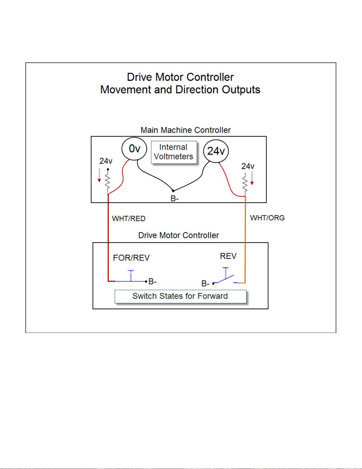
Drive Motor Circuit Description - SC750 and SC800 models.
Component Locations
Troubleshooting
Reading LED Trip Type Values
Does Not Propel Forward or Reverse with No Trip Type set
Removal and Installation
Speed Limit Potentiometer â ST models
Speed Limit Potentiometer â Non-ST models
Reverse Switch â ST models
Handle Wiring Connections - ST models
Paddle Position Sensor â Non-ST models - SC750, SC800
Paddle Centering Springs - Non-ST models - SC750, SC800
Drive Wheel
Transaxle
Transaxle Drive Motor Carbon Brushes
Specifications
_GoBack
Page 145/164
Page 1
Page 2
Page 3
Page 4
Page 5
Page 6
Page 7
Page 8
Page 9
Page 10
Page 11
Page 12
Page 13
Page 14
Page 15
Page 16
Page 17
Page 18
Page 19
Page 20
Page 21
Page 22
Page 23
Page 24
Page 25
Page 26
Page 27
Page 28
Page 29
Page 30
Page 31
Page 32
Page 33
Page 34
Page 35
Page 36
Page 37
Page 38
Page 39
Page 40
Page 41
Page 42
Page 43
Page 44
Page 45
Page 46
Page 47
Page 48
Page 49
Page 50
Page 51
Page 52
Page 53
Page 54
Page 55
Page 56
Page 57
Page 58
Page 59
Page 60
Page 61
Page 62
Page 63
Page 64
Page 65
Page 66
Page 67
Page 68
Page 69
Page 70
Page 71
Page 72
Page 73
Page 74
Page 75
Page 76
Page 77
Page 78
Page 79
Page 80
Page 81
Page 82
Page 83
Page 84
Page 85
Page 86
Page 87
Page 88
Page 89
Page 90
Page 91
Page 92
Page 93
Page 94
Page 95
Page 96
Page 97
Page 98
Page 99
Page 100
Page 101
Page 102
Page 103
Page 104
Page 105
Page 106
Page 107
Page 108
Page 109
Page 110
Page 111
Page 112
Page 113
Page 114
Page 115
Page 116
Page 117
Page 118
Page 119
Page 120
Page 121
Page 122
Page 123
Page 124
Page 125
Page 126
Page 127
Page 128
Page 129
Page 130
Page 131
Page 132
Page 133
Page 134
Page 135
Page 136
Page 137
Page 138
Page 139
Page 140
Page 141
Page 142
Page 143
Page 144
Page 145
Page 146
Page 147
Page 148
Page 149
Page 150
Page 151
Page 152
Page 153
Page 154
Page 155
Page 156
Page 157
Page 158
Page 159
Page 160
Page 161
Page 162
Page 163
Page 164
Contents
Table of Contents
Search
Previous
Next
Troubleshooting
Bookmarks
Loading ...
Loading ...
Loading ...
Service Manual: SC750, SC800, SC 750 ST
, SC800 ST
Form Number 56043150
Page 145
Dri
ve Mot
or Circuit Description - SC750 and SC800 models.
Loading ...
Loading ...
Loading ...
File type: PDF
File name: Nilfisk-SC800-manual.pdf
File size: 14.11 MB
File Language: English
Pages: 164
Author: Nilfisk
Published: 2020-11-19
Updated: 2023-06-21
Download File
Table of Contents
×
General Information
6
Service Manual Purpose and Application
6
Other Reference Manuals
7
Conventions
7
Transporting the Machine
7
Towing
7
Cautions and Warnings
7
Symbols
7
General Safety Instructions
8
General Machine Description
9
Nameplate
9
Know Your Machine
10
Control Panel â SC750 and SC800 (Membrane Switch Control Panel)
10
Control Panel â SC750 ST and SC800 ST (Toggle Switch Control Panel)
13
Machine Specifications â SC750 and SC750 ST
15
Machine Specifications â SC800 and SC800 ST
16
Machine Maintenance
17
Lubricating the Machine
18
Chassis System
19
Functional Description
19
Control system
20
Functional Description
20
Component Locations
21
Troubleshooting
22
Fault Codes
22
Fault Code Table
22
Service Test Mode
26
Programming Options âSC750 ST and SC800 ST Models (control panel with rocker switches)
29
Programming Options â SC750 and SC800 models (Control Panel with membrane switches)
33
Removal and Installation
38
Main Machine Controller SC750 ST and SC800 ST Models (Early Build)
38
Main Machine Controller SC750 ST and SC800 ST Models (Later Build)
40
Main Machine Controller SC750 and SC800 Models (Early Build)
40
Main Machine Controller SC750 and SC800 Models (Later build)
44
Rocker Switches - ST Models
50
Specifications
51
Shop Measurements â Main Machine Controller
51
Electrical System
54
Functional Description
54
General
54
On-board Battery Charger
55
Delta-Q IC650 Battery Charging Profile Table
57
Electrical Panel Components
59
Maintenance and Adjustments
60
Battery Maintenance and Recharging
60
Troubleshooting
60
Insufficient Machine Operation Time
60
The Battery Charger Does Not Charge
60
Removal and Installation
61
Batteries
61
Battery Charger - S.P.E.
62
Battery Charger - Delta-Q.
63
Low Voltage Cut Out Threshold Voltages
64
Battery Run Time
64
Battery Compartment Dimensions
64
Wiring Diagram - Non-ST, 56112170 Rev D, Early (before SN 4000077687)
65
Wiring Diagram - Non-ST, 56383889 Rev E, Late (Since SN 4000077687)
66
Wiring Diagram - ST, 56112180 REV C, Early (before SN 4000077687)
67
Wiring Diagram - ST, 56383366 REV E, Late (since SN 4000077687)
68
Wiring Harness Configuration Diagram - Non-ST, 56112171 REV D, Early (before SN 4000077687)
69
Wiring Harness Configuration Diagram - Non-ST, 56383890 Rev A, Late (since SN 4000077687)
70
Wiring Harness Configuration Diagram - ST, 56112181 REV C, Early (before SN 4000077687)
71
Wiring Harness Configuration Diagram - ST, 56383367 REV B, Late (since SN 4000077687)
72
TrackClean Connections, With Access Control 56384628 Rev A
73
TrackClean Electrical Connections, Without Access Control 56384627 Rev A
74
Options and Accessories
75
Battery Fill Indicator
75
Battery Watering Kit
75
Hour Meter
76
On-board Battery Charger
76
Wiring for On-board Charger
76
Parking Brake
78
Laser
78
TrackClean
78
Recovery System
79
Functional Description
79
Component Locations
80
Troubleshooting
81
Vacuum Motor Does Not Turn On (Scrub function works)
81
Insufficient Water Pickup
81
Removal and Installation
83
Vacuum Motor
83
Specifications
85
Vacuum Motor
85
Vacuum Performance:
85
Vacuum Motor Amp Draw
85
Special Tools
85
Scrub System â Cylindrical
86
Functional Description
86
Component Locations
89
Troubleshooting
91
Scrub Motors Do Not Turn On
91
Brush Head Will Not Raise or Lower
91
Removal and Installation
93
Scrub Brush
93
Brush Drive Belt
95
Brush Head Actuator.
96
Brush Motor
97
Motor Carbon Brushes
99
Specifications
101
Scrub Motor Total Amp Draw
101
Scrub Motor Speed
101
Scrub Force
101
Brush Head Actuator Amp Draw
101
Brush Contactor
101
Scrub System, Disc
102
Functional Description
102
Scrubbing
102
Brush Disc Remove Feature
105
Component Locations
107
Troubleshooting
108
Scrub Motors Do Not Turn On
108
Scrub Deck Will Not Raise or Lower
108
Removal and Installation
110
Scrub Brush
110
Brush Head
110
Scrub Motor Carbon Brushes
111
Brush Head Actuator
112
Specifications
113
Scrub Motor Amp Draw
113
Scrub Motor Total Amp Draw
113
Scrub Motor Speed
113
Scrub Force
113
Brush Head Actuator Amp Draw
113
Brush Contactor
113
Gas Spring
113
Scrub System, Rev
114
Functional Description
114
Scrubbing
114
Functional Circuit Diagram, Scrub System - REV
116
Component Locations
117
Troubleshooting
118
Scrub Motors Do Not Turn On
118
Scrub Deck Will Not Raise or Lower
118
Removal and Installation
120
Brush Head
120
Brush Motor
121
Drive Motor, Bearing and Eccentric
122
Motor Plate and Isolators
123
Scrub Motor Carbon Brushes
125
Brush Head Actuator
128
Specifications
129
Scrub Motor Amp Draw
129
Scrub Motor Total Amp Draw
129
Scrub Motor Speed
129
Scrub Force
129
Brush Head Actuator Amp Draw
129
Brush Contactor
129
Gas Spring
129
Solution System
130
Functional Description
130
Component Locations
132
Maintenance and Adjustments
133
Solution Filter Cleaning
133
Troubleshooting
134
Insufficient Solution Flow
134
Solution Leaks After Machine Is Shut Off
134
Detergent Is Not Being Added to the Solution (Machines with optional detergent mixing system)
134
Removal and Installation
135
Solution Valve
135
Solution Tank
135
Specifications
136
Squeegee System
137
Functional Description
137
Component Locations
137
Maintenance and Adjustments
138
Adjusting Squeegee Tilt
138
Troubleshooting
138
Leaving Streaks on the Floor
138
Removal and Installation
139
Squeegee Tool
139
Squeegee Support
139
Squeegee Blades
140
Wheel System Non-Traction
141
Functional Description
141
Component Locations
141
Wheel System, Traction
142
Functional Description
142
Drive Motor Circuit Description - SC750 ST and SC800 ST models.
142
Drive Motor Circuit Description - SC750 and SC800 models.
145
Component Locations
148
Troubleshooting
149
Reading LED Trip Type Values
149
Does Not Propel Forward or Reverse with No Trip Type set
155
Removal and Installation
156
Speed Limit Potentiometer â ST models
156
Speed Limit Potentiometer â Non-ST models
156
Reverse Switch â ST models
157
Handle Wiring Connections - ST models
158
Paddle Position Sensor â Non-ST models - SC750, SC800
159
Paddle Centering Springs - Non-ST models - SC750, SC800
161
Drive Wheel
162
Transaxle
162
Transaxle Drive Motor Carbon Brushes
163
Specifications
164
_GoBack
79
Search:
×
Search