Loading ...
Loading ...
Loading ...
Service Manual: SC750, SC800, SC 750 ST, SC800 ST
Form Number 56043150 Page 26
Service Test Mode
Some outputs (like the scrub brush motors) are only turned on when other condions are met, such as when the ma-
chine is moving. It can be dicult to check for voltage to the scrub brush motors while the machine is moving. Also, if
voltage is not present, it leaves in queson what other condions may not have been met yet. The Service Test Mode
solves these problems for the technician. In Service Test Mode the technician can request that the Main Machine Con-
troller ignore all other condions and directly turn on the scrub brush motors as well as other outputs. Service Test
mode can also be used to verify that certain inputs are seen by the controller. The concept is the same for all models
but the procedure is very dierent depending on whether you are working on an” ST” model (control panel with rocker
switches – SC750 ST and SC800 ST) or a “non-ST” model (control panel with membrane switches – SC750 and SC800).
See appropriate secons below.
Service Test Mode –SC750 ST and SC800 ST Models (Control Panel with rocker switches)
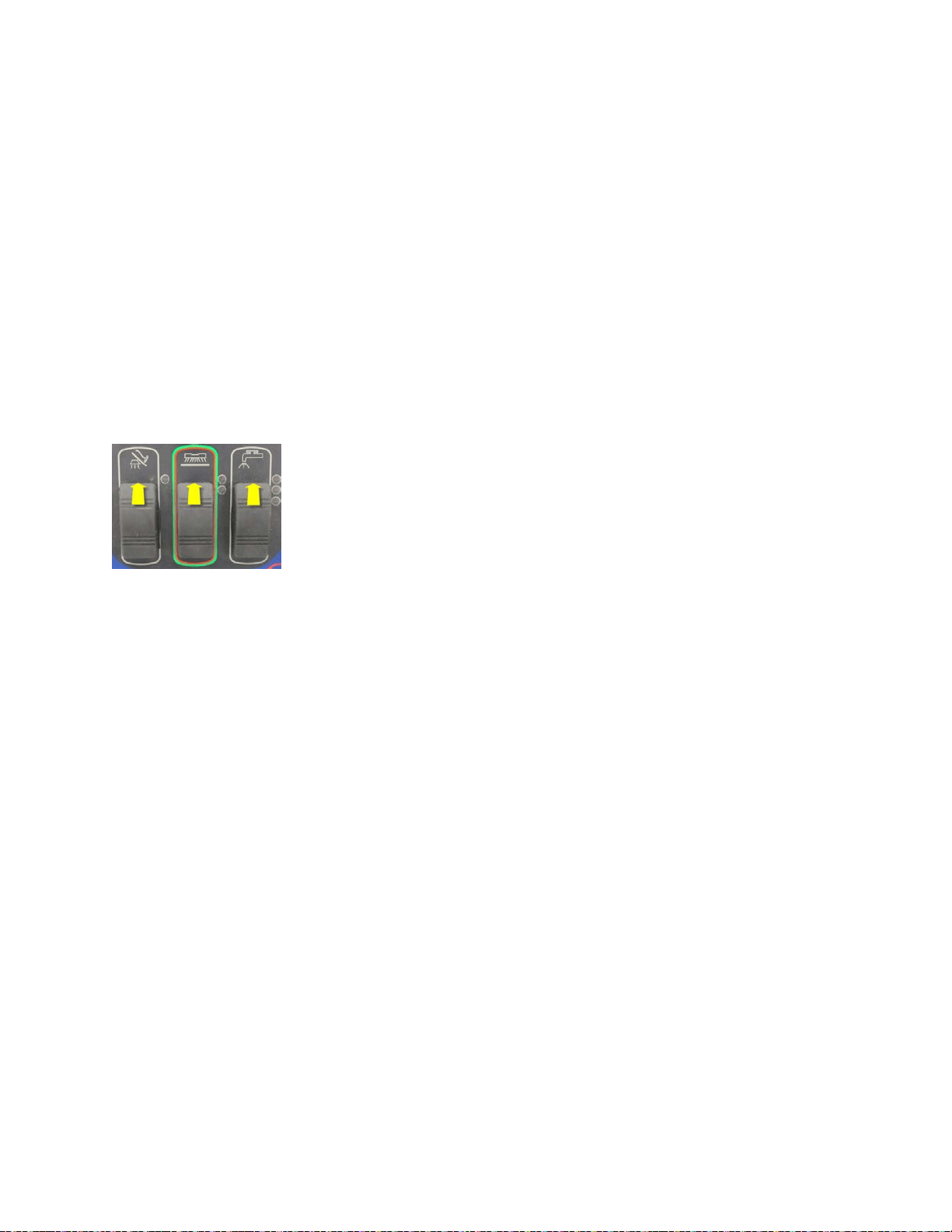
To enter the service test mode: (Start with the baery charger unplugged and the key o)
1. Hold all three switches (Vacuum, Scrub and Soluon) in the up (forward) posion while turning the key on.
2. Wait approximately 3 seconds unl all of the LEDs light up and then turn o. The low soluon ow indicator light
should remain on to conrm that you are in the service test mode.
Now that you are in service test mode, you can request that the controller operate the various outputs and verify certain
inputs via the indicator light operaon. If a fault occurs the Fault LED will display the fault.
To exit the service test mode: Turn the Key Switch o.
Output Tests
Brush Deck Li Actuator – Press the Scrub Switch forward to move the actuator downward to the next posion. Watch
for the actuator to move. Press the Scrub Switch backward to move the actuator up one posion. The Scrub Indicator
LEDs indicate the current actuator posion. Neither LED is ON when deck is raised, lower LED is ON when deck is at
low scrub pressure, both are on for high pressure. Machines with disc scrub decks have three posions while cylindrical
decks have only two. Note: If the switch inputs are not reporng correct informaon, the controller will not understand
the current actuator posion and will not aempt to move the actuator.
Soluon Solenoid – Press the Soluon Switch forward to cycle the soluon solenoid on and o. The high soluon ow
indicator will be on while in the test mode. Listen for the Solenoid to click on and o. Press the Soluon Switch forward
again to stop cycling the solenoid.
Brush Motor Contactor – Press the Soluon Switch backward to energize the brush motor contactor. The medium
soluon ow indicator will be ON when energizing the contactor. Listen for the contactor to click and look to see if the
brushes are rotang. Press the Soluon Switch backward again to de-energize the contactor.
Vacuum Motor Relay – Press the Vacuum Switch forward to energize the Vacuum Motor Relay. The Vacuum Indicator
will be ON when energizing the relay. The vacuum motor should come ON. Press the Vacuum Switch backward to de-
energize the relay.
Loading ...
Loading ...
Loading ...