Loading ...
Loading ...
Loading ...
16
• Place the saw on a rm, level work
surface where there is room for
handling and properly supporting
the workpiece.
• Support the saw on a level work
surface.
• Always bolt or clamp the saw to its
support.
• To prevent binding and inaccuracy,
be sure the mounting surface is not
warped or otherwise uneven. If the
saw rocks on the surface, place a
thin piece of material under one saw
foot until the saw sits rmly on the
mounting surface.
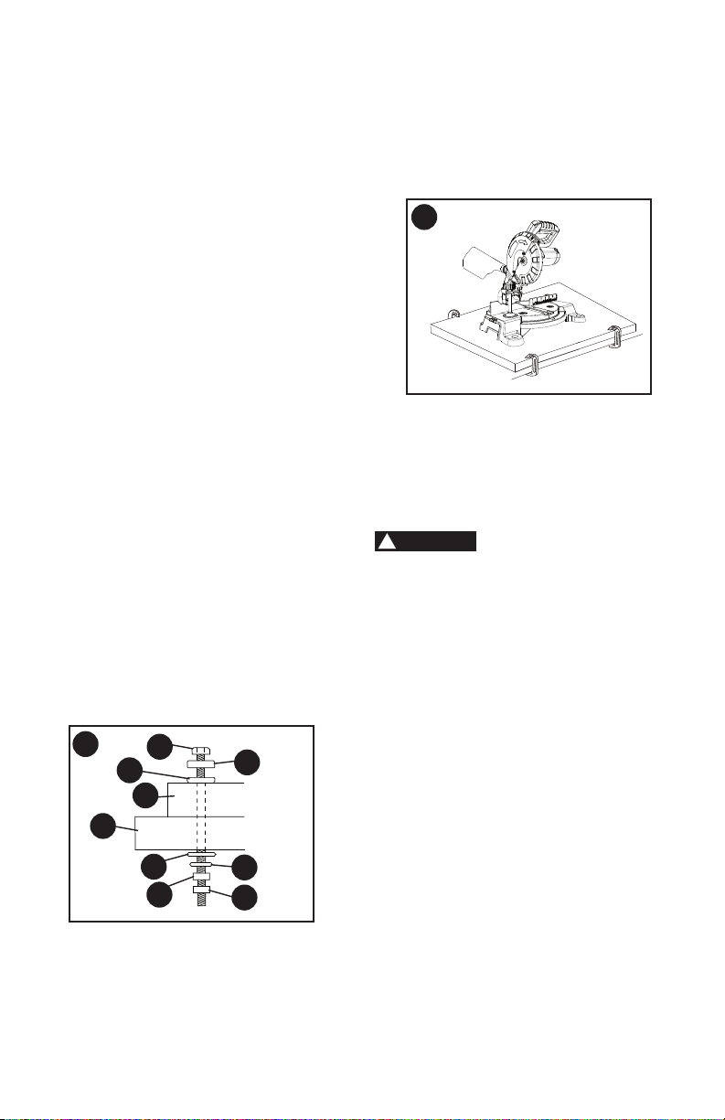
Mounting Instructions
•
For stationary use,
place the saw
in the desired location, directly on a
workbench where there is room for
handling and proper support of the
workpiece. The base of the saw has
four mounting holes. Bolt the base of
the miter saw (1) to the work surface (5),
using the fastening method as shown in
Figure K
.
1. Miter saw base
2. Hex head bolt
3. Rubber washer
4. Flat washer
5. Workbench
6. Flat washer
7. Lockwasher
8. Hex nut
9. Jam nut
NOTE: Mounting hardware is not included
with this tool. Bolts, nuts, washers, &
screws must be purchased separately.
•
For portable use,
place the saw on
a 3/4 in. thick piece of plywood. Bolt
the base of the miter saw securely to
the plywood using the mounting holes
on the base. Use C-clamps to clamp
this mounting board to a stable work
surface at the worksite.
(Figure L)
NOTE: If a miter saw stand is used,
please follow all instructions shown in that
product’s instructions for proper mounting.
BEVEL STOP ADJUSTMENTS
(FIGURE M, N, O)
To avoid injury from
unexpected starting or electrical shock,
make sure the trigger is released and
remove the power cord from the power
source.
90°(0°) Bevel Adjustment (Figure M)
• Set the miter angle to zero degrees.
Loosen bevel lock handle (1) and tilt
the cutting arm completely to the right.
Tighten the bevel lock handle.
• Lower and lock the cutting head. Place
a combination square (2) on the miter
table with the ruler against the table
and the heel of the square against the
saw blade.
• If the blade is not 90°(0°) square
with the table, loosen the bevel lock
handle (1), tilt the cutting head to
the left, loosen the locknut (3) with a
10 mm wrench. Then, adjust the set
screw in the locknut (3) clockwise or
counterclockwise with a 3 mm hex key.
NOTE: The locknut is at the right rear
side of the saw base.
L
K
4
2
3
1
5
6
8
7
9
WARNING
!
Loading ...
Loading ...
Loading ...