
1
7-1/4 IN. COMPOUND MITER SAW
INSTRUCTION MANUAL
CATALOG NUMBER
M1850BD TYPE 2
Thank you for choosing Black+Decker!
PLEASE READ BEFORE RETURNING THIS PRODUCT FOR
ANY REASON.
If you have a question or experience a problem with your Black+Decker
purchase, go to http://www.blackanddecker.com/instantanswers
If you can’t find the answer or do not have access to the Internet, call
1-844-437-5095 from 8:30 am to 5 p.m. EST Mon. - Fri. to speak with an
agent. Please have the catalog number available when you call.
SAVE THIS MANUAL FOR FUTURE REFERENCE.
VEA EL ESPANOL EN LA CONTRAPORTADA.
INSTRUCTIVO DE OPERACIÓN, CENTROS DE SERVICIO Y PÓLIZA DE GARANTÍA.
ADVERTENCIA: LÉASE ESTE INSTRUCTIVO ANTES DE USAR EL PRODUCTO.
To register your new product, call 1-844-437-5095
or visit www.BlackandDecker.com/NewOwner

2
SAFETY GUIDELINES - DEFINITIONS
It is important for you to read and understand this manual. The information it contains
relates to protecting YOUR SAFETY and PREVENTING PROBLEMS. The symbols
below are used to help you recognize this information.
: Indicates an imminently hazardous situation which, if not avoided, will
result in death or serious injury.
: Indicates a potentially hazardous situation which, if not avoided, could
result in death or serious injury.
: Indicates a potentially hazardous situation which, if not avoided, may
result in minor or moderate injury.
NOTICE: Used without the safety alert symbol indicates potentially hazardous
situation which, if not avoided, may result in property damage.
GENERAL POWER TOOL
SAFETY RULES
Read all safety warnings and all
instructions. Failure to follow the
warnings and instructions may result in
electric shock, re and/or serious injury.
SAVE ALL WARNINGS AND
INSTRUCTIONS FOR FUTURE
REFERENCE
The term “power tool” in the warnings
refers to your mains-operated (corded)
power tool or battery-operated (cordless)
power tool.
1) WORK AREA SAFETY
a) Keep work area clean and well
lit. Cluttered or dark areas invite
accidents.
b) Do not operate power tools in
explosive atmospheres, such
as in the presence of ammable
liquids, gases or dust. Power tools
create sparks which may ignite the
dust or fumes.
c) Keep children and bystanders
away while operating a power tool.
Distractions can cause you to lose
control.
2) ELECTRICAL SAFETY
a) Power tool plugs must match the
outlet. Never modify the plug in
any way. Do not use any adapter
plugs with earthed (grounded)
power tools. Unmodied plugs and
matching outlets will reduce risk of
electric shock.
b) Avoid body contact with earthed
or grounded surfaces such as
pipes, radiators, ranges and
refrigerators. There is an increased
risk of electric shock if your body is
earthed or grounded.
WARNING
!
DANGER
!
CAUTION
!
WARNING
!
c) Do not expose power tools to rain
or wet conditions. Water entering
a power tool will increase the risk of
electric shock.
d) Do not abuse the cord. Never use
the cord for carrying, pulling or
unplugging the power tool. Keep
cord away from heat, oil, sharp
edges or moving parts. Damaged
or entangled cords increase the risk
of electric shock.
e) When operating a power tool
outdoors, use an extension cord
suitable for outdoor use. Use
of a cord suitable for outdoor use
reduces the risk of electric shock.
f) If operating a power tool in damp
location is unavoidable, use a
ground fault circuit interrupter
(GFCI) protected supply. Use of
a GFCI reduces the risk of electric
shock.
3) PERSONAL SAFETY
a) Stay alert, watch what you are
doing and use common sense
when operating a power tool. Do
not use a power tool while you
are tired or under the inuence
of drugs, alcohol or medication.
A moment of inattention while
operating power tools may result in
serious personal injury.
b) Use personal protective
equipment. Always wear eye
protection. Protective equipment
such as dust mask, nonskid
safety shoes, hard hat, or hearing
protection used for appropriate
conditions will reduce personal
injuries.
c) Prevent unintentional starting.
Ensure the switch is in the off
position before connecting to
power source and/ or battery
pack, picking up or carrying the

3
SAFETY INSTRUCTIONS FOR
MITER SAWS
• Miter saws are intended to cut wood
or wood-like products, they cannot
be used with abrasive cut-off wheels
for cutting ferrous material such as
bars, rods, studs, etc. Abrasive dust
causes moving parts such as the lower
guard to jam. Sparks from abrasive
cutting will burn the lower guard, the
kerf insert and other plastic parts.
• Use clamps to support the workpiece
whenever possible. If supporting the
workpiece by hand, you must always
keep your hand at least 100 mm from
either side of the saw blade. Do not
use this saw to cut pieces that are
too small to be securely clamped or
held by hand. If your hand is placed
too close to the saw blade, there is
an increased risk of injury from blade
contact.
• The workpiece must be stationary
and clamped or held against both the
fence and the table. Do not feed
the workpiece into the blade or cut
"freehand" in any way. Unrestrained
or moving workpieces could be thrown
at high speeds, causing injury.
WARNING
!
tool. Carrying power tools with your
nger on the switch or energizing
power tools that have the switch on
invites accidents.
d) Remove any adjusting key or
wrench before turning the power
tool on. A wrench or a key left
attached to a rotating part of the
power tool may result in personal
injury.
e) Do not overreach. Keep proper
footing and balance at all times.
This enables better control of the
power tool in unexpected situations.
f) Dress properly. Do not wear loose
clothing or jewelry. Keep your
hair, clothing and gloves away
from moving parts. Loose clothes,
jewelry or long hair can be caught in
moving parts.
g) If devices are provided for the
connection of dust extraction and
collection facilities, ensure these
are connected and properly used.
Use of dust collection can reduce
dust-related hazards.
4) POWER TOOL USE AND CARE
a) Do not force the power tool. Use
the correct power tool for your
application. The correct power tool
will do the job better and safer at the
rate for which it was designed.
b) Do not use the power tool if the
switch does not turn it on and
off. Any power tool that cannot
be controlled with the switch is
dangerous and must be repaired.
c) Disconnect the plug from the
power source and/or the battery
pack from the power tool before
making any adjustments,
changing accessories, or storing
power tools. Such preventive safety
measures reduce the risk of starting
the power tool accidentally.
d) Store idle power tools out of
the reach of children and do not
allow persons unfamiliar with the
power tool or these instructions
to operate the power tool. Power
tools are dangerous in the hands of
untrained users.
e) Maintain power tools. Check
for misalignment or binding of
moving parts, breakage of parts
and any other condition that may
affect the power tool’s operation.
If damaged, have the power
tool repaired before use. Many
accidents are caused by poorly
maintained power tools.
f) Keep cutting tools sharp and
clean. Properly maintained cutting
tools with sharp cutting edges are
less likely to bind and are easier to
control.
g) Use the power tool, accessories
and tool bits, etc. in accordance
with these instructions, taking
into account the working
conditions and the work to be
performed. Use of the power tool
for operations different from those
intended could result in a hazardous
situation.
5) SERVICE
a) Have your power tool serviced by
a qualied repair person using
only identical replacement parts.
This will ensure that the safety of the
power tool is maintained.
People with electronic devices, such
as pacemakers, should consult their
physician(s) before using this product.
Operation of electrical equipment in
close proximity to a heart pacemaker
could cause interference or failure of
the pacemaker.

4
• Push the saw through the workpiece.
Do not pull the saw through the
workpiece. To make a cut, raise the
saw head and pull it out over the
workpiece without cutting, start the
motor, press the saw head down and
push the saw through the workpiece.
Cutting on the pull stroke is likely to
cause the saw blade to climb on top of
the workpiece and violently throw the
blade assembly towards the operator.
• Never cross your hand over the
intended line of cutting either in front
or behind the saw blade. Supporting
the workpiece "cross handed" i.e.
holding the workpiece to the right of the
saw blade with your left hand or vice
versa is very dangerous.
• Do not reach behind the fence with
either hand closer than 100 mm
from either side of the saw blade, to
remove wood scraps, or for any other
reason while the blade is spinning.
The proximity of the spinning saw blade
to your hand may not be obvious and
you may be seriously injured.
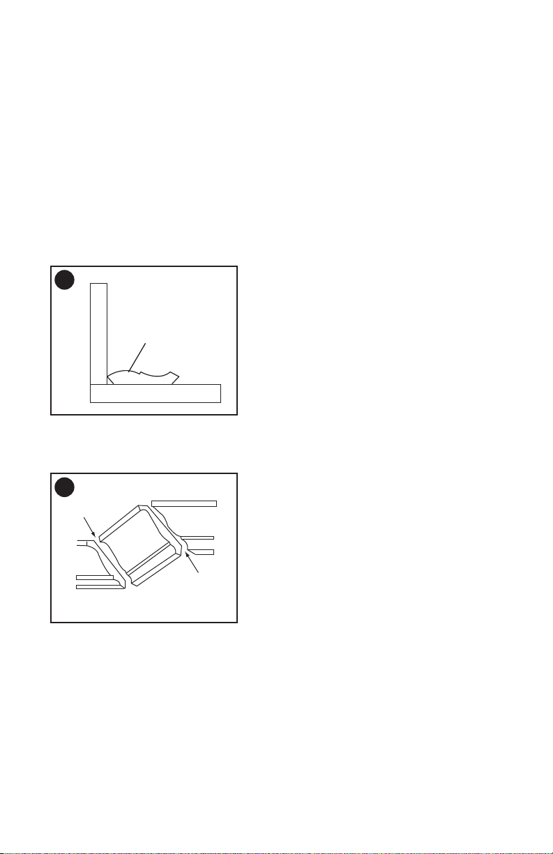
• Inspect your workpiece before
cutting. If the workpiece is bowed
or warped, clamp it with the outside
bowed face toward the fence. Always
make certain that there is no gap
between the workpiece, fence and
table along the line of the cut. Bent
or warped workpieces can twist or shift
and may cause binding on the spinning
saw blade while cutting. There should
be no nails or foreign objects in the
workpiece.
• Do not use the saw until the table is
clear of all tools, wood scraps, etc.,
except for the workpiece. Small debris
or loose pieces of wood or other objects
that contact the revolving blade can be
thrown with high speed.
• Cut only one workpiece at a time.
Stacked multiple workpieces cannot be
adequately clamped or braced and may
bind on the blade or shift during cutting.
• Ensure the miter saw is mounted or
placed on a level, rm work surface
before use. A level and rm work
surface reduces the risk of the miter
saw becoming unstable.
• Plan your work. Every time you
change the bevel or miter angle
setting, make sure the adjustable
fence is set correctly to support the
workpiece and will not interfere with
the blade or the guarding system.
Without turning the tool "ON" and with
no workpiece on the table, move the saw
blade through a complete simulated cut
to assure there will be no interference or
danger of cutting the fence.
• Provide adequate support such as
table extensions, saw horses, etc. for
a workpiece that is wider or longer
than the table top. Workpieces longer
or wider than the miter saw table can
tip if not securely supported. If the
cut-off piece or workpiece tips, it can
lift the lower guard or be thrown by the
spinning blade.
• Do not use another person as a
substitute for a table extension or as
additional support. Unstable support
for the workpiece can cause the blade
to bind or the workpiece to shift during
the cutting operation pulling you and the
helper into the spinning blade.
• The cut-off piece must not be
jammed or pressed by any means
against the spinning saw blade. If
conned, i.e. using length stops, the
cut-off piece could get wedged against
the blade and thrown violently.
• Always use a clamp or a xture
designed to properly support round
material such as rods or tubing. Rods
have a tendency to roll while being cut,
causing the blade to "bite" and pull the
work with your hand into the blade.
• Let the blade reach full speed before
contacting the workpiece. This will
reduce the risk of the workpiece being
thrown.
• If the workpiece or blade becomes
jammed, turn the miter saw off. Wait
for all moving parts to stop and
disconnect the plug from the power
source and/or remove the battery
pack. Then work to free the jammed
material. Continued sawing with a
jammed workpiece could cause loss of
control or damage to the miter saw.
• After nishing the cut, release the
switch, hold the saw head down
and wait for the blade to stop before
removing the cut-off piece. Reaching
with your hand near the coasting blade
is dangerous.
• Hold the handle rmly when making
an incomplete cut or when releasing
the switch before the saw head is
completely in the down position. The
braking action of the saw may cause
the saw head to be suddenly pulled
downward, causing a risk of injury.

5
• Do not use this saw to cut tree limbs
or logs.
• Never use blades recommended for
operation at less than 5000 RPM.
• Do not use this saw to cut ber cement
board. This miter saw is not intended to
cut ber cement board.
Additional warnings are
listed throughout this manual. Please
review all before operating this power
tool.
• ADDITIONAL INFORMATION
regarding the safe and proper operation
of power tools (i.e., a safety video) is
available from the Power Tool Institute,
1300 Sumner Avenue, Cleveland, OH
44115-2851 (www.powertoolinstitute.
com). Information is also available
from the National Safety Council, 1121
Spring Lake Drive, Itasca, IL 60143-
3201. Please refer to the American
National Standards Institute ANSI 01.1
Safety Requirements for Woodworking
Machines and the U.S. Department of
Labor OSHA 1910.213 Regulations.
Do not connect unit to
electrical power source until complete
instructions are read and understood.
Always wear proper
personal hearing protection that
conforms to ANSI S12.6 (S3.19) during
use. Under some conditions and duration
of use, noise from this product may
contribute to hearing loss.
NEVER MAKE ANY CUT
UNLESS THE MATERIAL IS SECURED
ON THE TABLE AND AGAINST THE
FENCE.
WARNING
!
WARNING
!
WARNING
!
WARNING
!
PROPOSITION 65 WARNING
WARNING
!
Drilling, sawing, sanding
or machining wood products can
expose you to wood dust, a substance
known to the State of California to
cause cancer. Avoid inhaling wood
dust or use a dust mask or other
safeguards for personal protection.
For more information go to:
www.P65Warnings.ca.gov/wood
Some examples of these chemicals are:
• lead from lead-based paints,
• crystalline silica from bricks and
cement and other masonry products,
and
• arsenic and chromium from
chemically-treated lumber.
Your risk from these exposures varies,
depending on how often you do this type
of work. To reduce your exposure to these
chemicals: work in a well ventilated area,
and work with approved safety equipment,
such as those dust masks that are
specially designed to lter out microscopic
particles.
Handling the power cord on this product
may expose you to chemicals known to
the state of California to cause cancer and
birth defects or other reproductive harm.
Wash hands after handling.
For more information go to
www.65Warnings.ca.gov
WARNING
!
Use of this tool can
generate and/or disperse dust, which
may cause serious and permanent
respiratory or other injury. Always use
NIOSH/OSHA approved respiratory
protection appropriate for the dust
exposure. Direct particles away from face
and body.
• Wear appropriate hearing protection
during use. Under some conditions
and duration of use, noise from this
product may contribute to hearing loss.
WARNING
!
ALWAYS use safety
glasses. Everyday eye glasses are NOT
safety glasses. Also use face or dust
mask if cutting operation is dusty.
ALWAYS WEAR CERTIFIED SAFETY
EQUIPMENT:
• ANSI Z87.1 eye protection (CAN/CPA
Z94.3),
• ANSI S12.6 (S3.19) hearing
protection,
• NOSH/OSHA respiratory protection.
6
ELECTRICAL
REQUIREMENTS AND
SAFETY
POWER SUPPLY AND MOTOR
SPECIFICATIONS
The AC motor used in this saw is a
universal, nonreversible type.
To avoid electrical
hazards, re hazards, or damage to the
tool, use proper circuit protection. Your
saw is wired at the factory for
120 V operation. Connect to a 120 V,
9 A circuit and use a 9 A time delay
fuse or circuit breaker. To avoid shock
or re, if power cord is worn or cut, or
damaged in any way, have it replaced
immediately.
ELECTRICAL REQUIREMENTS -
DOUBLE INSULATED
The power tool is double insulated to
provide a double thickness of insulation
between you and tool’s electrical system.
All exposed metal parts are isolated from
the internal metal motor components with
protecting insulation.
Replacement parts – When servicing,
use only identical replacement parts.
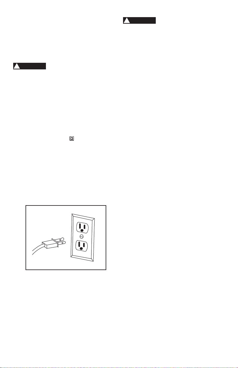
Polarized plugs – This saw has a plug
that looks like the one shown below:
To reduce the risk of electrical shock,
this saw has a polarized plug (one blade
is wider than the other). This plug will t
in a polarized outlet only one way. If the
plug does not t fully in the outlet, reverse
the plug. If it still does not t, contact a
qualied electrician to install the proper
outlet. Do not change the plug in any way.
WARNING
!
WARNING
!
Double insulation does
not take the place of normal safety
precautions when operating this tool.
To avoid electrocution:
• Use only identical replacement parts
when servicing a tool with double
insulation. Servicing should be
performed by a qualied technician.
• Do not use power tools in wet or damp
locations or expose them to rain or
snow.
MOTOR SAFETY PROTECTION
IMPORTANT:
To avoid motor damage, the motor should
be blown out or vacuumed frequently to
keep sawdust from interfering with the
motor ventilation.
• Connect this saw to a 120 V, 9 A circuit
with a 9 A time-delay fuse or circuit
breaker. Using the wrong size fuse can
damage the motor.
• If the motor will not start, release the
trigger switch immediately. UNPLUG
THE SAW. Check the saw blade to
make sure it turns freely. If the blade
is free, try to start the saw again. If the
motor still does not start, refer to the
TROUBLESHOOTING GUIDE.
• If the tool suddenly stalls while cutting
wood, release the trigger switch,
unplug the tool and free the blade from
the wood. The saw may now be started
and the cut nished.
• FUSES may “blow” or circuit breakers
may trip frequently if:
• MOTOR is overloaded – overloading
can occur if you feed too rapidly or
make too many start/stops in a short
time.
• LINE VOLTAGE is more than 10%
above or below the nameplate
voltage rating. For heavy loads,
the voltage at motor terminals must
equal the voltage specied on the
nameplate.
• IMPROPER or dull saw blades are
used.
Polarized plugs

7
• Most motor troubles may be traced
to loose or incorrect connections,
overload, low voltage or inadequate
power supply wiring. Always check the
connections, the load and supply circuit
if the motor doesn’t run well. Check
minimum gauge for the length of cord
you are using on the chart below.
GUIDELINES FOR EXTENSION CORDS
Use a proper extension cord. Make sure
your extension cord is in good condition.
When using an extension cord, be sure to
use one heavy enough to carry the current
your product will draw. An undersized cord
will cause a drop in line voltage, resulting
in loss of power and overheating. The
table below shows the correct size to use
depending on cord length and nameplate
ampere rating. If in doubt, use the next
heavier gauge. The smaller the gauge
number, the heavier the cord.
Be sure your extension cord is
properly wired and in good condition.
Always replace a damaged extension cord
or have it repaired by a qualied person
before using it. Protect your extension
cords from sharp objects, excessive heat
and damp or wet areas.
Use a separate electrical circuit for
your tools. This circuit must not be less
than a #18 wire with a 9 A time lag fuse.
NOTE: When using an extension cord on
a circuit with a #18 wire, the extension
cord must not exceed 25 feet in length.
Before connecting the tool to the power
line, make sure the switch is in the OFF
position and the electric current is rated
the same as the current stamped on the
motor nameplate, running at a lower
voltage will damage the motor.
MINIMUM GAUGE FOR EXTENSION CORDS (AWG)
(When using 120 volts only)
Ampere Rating Total length of Cord
More Than Not More Than 25ft. 50ft. 100ft. 150ft.
0 6 18 16 16 14
6 10 18 16 14 12
10 12 16 16 14 12
12 16 14 12
Not Recommended
In all cases make certain
the receptacle in question is properly
grounded. If you are not sure, have
a certied electrician check the
receptacle.
GLOSSARY OF TERMS
AMPERAGE (AMPS) – A measure of
the ow of electric current. Higher ratings
generally means the tool is suited for
heavier use.
ARBOR LOCK – Allows the user to keep
the blade from rotating while tightening
or loosening the arbor bolt during blade
replacement or removal.
BASE – Supports the table, holds
accessories and allows for workbench or
leg set mounting.
BEVEL LOCK HANDLE – Locks the miter
saw at a desired bevel angle.
BEVEL SCALE – To measure the bevel
angle of the saw blade 0° to 45° left.
CARBIDE TIPPED – Extremely hard steel
pieces with sharp cutting edges fastened
to cutting tools such as saw blades.
COVER PLATE SCREW – Loosen this
screw and rotate the plate for access to
the blade arbor bolt.
DOUBLE-INSULATED – A form of
electrical protection featuring two
separate insulation systems to help
protect against electrical shock.
EXTENSION CORD – An electric cord
used between power tools and outlets to
extend the range of the tools. The more
amerage your tool uses, the longer the
distance, the larger the size of the wire
needed in your extension cord.
EYE PROTECTION – Googles or
spectacles intended to protect your
eyes. Eye protection should meet the
requirements of ANSI Z.87.1 (USA) or
CSA Z94.3-M88 (Canada).
FACE SHIELD – An impact resistant
shield that helps to protect your face from
chips, sparks, small debris. Should only
be used in conjunction with additional eye
protection.
CAUTION
!

8
FENCE – Helps to keep the workpiece
from moving when sawing. Scaled to
assist with accurate cutting.
GUARD – Protective devise that forms
a barrier between a hazardous object
such as a blade, wheel or cutter and the
operator.
HOLD-DOWN LATCH – Locks the miter
saw in the lowered position for compact
storage and transportation.
INSTRUCTION MANUAL – Booklet
accompanying your power tool that
describes the hazards and safe operation
procedures, outlines basic tool operation,
care and maintenance.
MITER HANDLE – Used to rotate the
table, and to rotate the saw to a right or
left cutting position.
MITER SCALE – Measures the miter
angle of the saw blade. Positive stop
index points have been provided at 0°,
15°, 22.5°, 31.6° and 45° right and left.
MOUNTING HOLES – To mount the miter
saw to a stable surface.
ON/OFF TRIGGER SWITCH – To start
the tool, squeeze the trigger. Release the
trigger to turn off the miter saw.
POSITIVE STOP LOCKING LEVER –
Locks the miter saw at a preset positive
stop for the desired miter angle.
SWITCH HANDLE – The switch handle
contains the trigger switch and the laser
on/off switch. The blade is lowered into
the workpiece by pushing down on the
handle. The saw will return to its upright
position when the handle is released.
WARNING LABELS – Read and
understand for your own safety. Make
sure all labels are present on machine and
legible.
BLADE WRENCH STORAGE –
Convenient storage to prevent misplacing
the blade wrench.
WOODWORKING TERMS
ARBOR – The shaft on which a blade is
mounted.
BEVEL CUT – An angle cut made through
the face of the workpiece.
COMPOUND CUT – An angled cut to
both the edge and face of a board, most
common use is with crown molding.
CROSS CUT – A cut which runs across
the board perpendicular to the grain.
FREEHAND – Performing a cut without
using a fence (guide), hold down or other
proper device to prevent the workpiece
from twisting during the cutting operation.
HEEL – Misalignment of the blade.
KERF – The width of a saw cut,
determined by the thickness and set of the
blade.
KICKBACK – sudden and unintended
movement of the tool or workpiece. It is
typically caused by binding or pinching of
the workpiece.
MITER CUT – A miter is a type of joint
where the two parts to be joined are cut
at an angle, and typically the nished joint
forms a 90-degree angle. Also commonly
spelled “mitre”.
REVOLUTIONS PER MINUTE (RPM)
– The number of turns completed by a
spinning object in one minute.
SAW BLADE PATH – The area of the
workpiece or table top directly in line with
the travel of the blade or the part of the
workpiece which will be cut.
SET – The distance between two saw
blade tips, bent outward in opposite
directions to each other. The further apart
the tips are, the greater the set.
THIN-KERF BLADE – Thinner than
normal blades, remove less material,
smaller kerfs (between 0.065 in. and
0.070 in.). Blade thinness also may
increase the heat generated while cutting.
WORKPIECE – The wood being cut. The
surfaces of a workpiece are commonly
referred to as faces, ends and edges.

9
SYMBOLS
Your power tool and its Instruction Manual
may contain “WARNING ICONS” (a picture
symbol intended to alert you to, and/or
instruct you how to avoid a potentially
hazardous condition). Understanding
and heeding these symbols will help you
operate your tool better and safer. Shown
below are some of the symbols you may
see.
SAFETY ALERT: Precautions that
involve your safety.
PROHIBITION
WEAR EYE PROTECTION: Always
wear safety goggles or safety
glasses with side shields.
READ AND UNDERSTAND
INSTRUCTION MANUAL: To
reduce the risk of injury, user and
all bystanders must read and
understand Instruction manual
before using this product.
SUPPORT AND CLAMP WORK
KEEP HANDS AWAY FROM
BLADE: Failure to keep your hands
away from the blade will result in
serious personal injury.
WEAR A MASK: Always wear a
face mask or dust mask.
WEAR HEARING PROTECTION:
To reduce the risk of induced
hearing loss, always wear a hearing
protection.
10
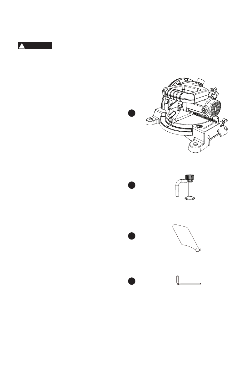
CARTON CONTENTS
1) Carefully remove the miter saw from the carton.
2) Separate and layout all of the parts. Carefully check them according to the
diagram below.
If any part is missing or damaged, please do not plug in or use
the miter saw until replacements have been obtained.
UNPACKING YOUR MITER SAW
1. Miter saw
2. Hold-down clamp
3. Dust bag
4. Blade wrench
1
2
3
4
WARNING
!
11
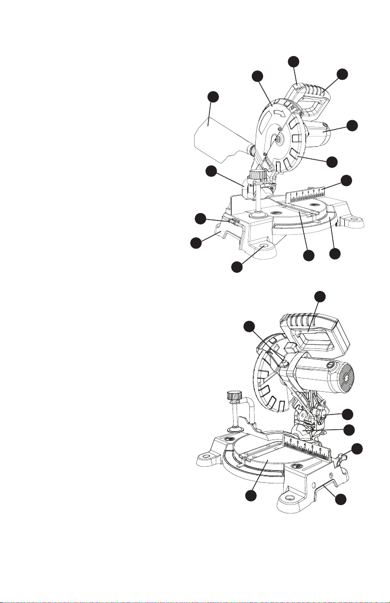
FUNCTIONAL DESCRIPTION
1. Upper blade guard
2. Safety lock-off button
3. Switch handle
4. Motor
5. Lower blade guard
6. Fence
7. Miter scale
8. Table insert
9. Mounting hole
10. Base
11. Blade wrench storage
12. Hold-down clamp
13. Dust bag
14. ON/OFF trigger switch
15. Hold-down latch
16. Bevel scale
17. Miter table locking lever
18. Hand hold for transportation
19. Turn table
20. Arbor lock button
2
11
1
3
4
5
6
7
8
9
10
12
13
14
15
16
17
18
19
20
12
ASSEMBLY AND
ADJUSTMENTS
• To avoid injury, do not connect this
miter saw to the power source until
it is completely assembled and
adjusted, and you have read and
understood this Instruction Manual.
• To reduce the risk of injury, turn
unit off and disconnect it from
power source before installing
and removing accessories, before
adjusting or when making repairs.
An accidental start-up can cause
injury.
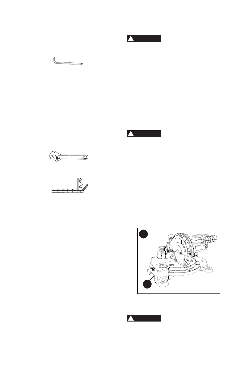
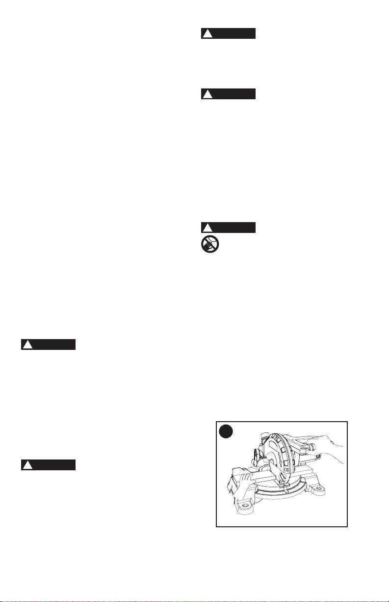
TRANSPORTING THE SAW (FIGURE A)
• To reduce the risk of injury, turn unit
off and disconnect it from power
source before installing and removing
accessories, before adjusting or
when making repairs. An accidental
start-up can cause injury.
• To reduce the risk of serious
personal injury, ALWAYS lock the
miter table locking lever, bevel lock
handle, and hold-down latch before
transporting saw.
• In order to conveniently carry the miter
saw from place to place, use the hand
holds (1) on the base.
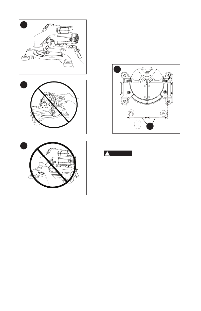
RELEASING THE CUTTING HEAD
(FIGURE B)
To avoid injury and
damage to the saw, transport or store
the miter saw with the cutting head
locked in the down position. Never
use the hold-down latch to hold the
cutting head in a down position for
cutting operations.
WARNING
!
WARNING
!
WARNING
!
A
1
TOOLS NEEDED TO REMOVE
OR INSTALL BLADE
Adjustable Wrench
Combination Square
Not Supplied
Supplied
TOOLS NEEDED FOR
ADJUSTMENT
Blade Wrench with
Phillips Head End and
6 mm Hex Head End
13
Unlocking
• Push down slightly on the switch
handle (1).
• Pull out the hold-down latch (2).
• Allow the cutting head to rise to the
uppermost position.
Locking
The hold-down latch
should be used ONLY when carrying or
storing the saw. NEVER use the hold-
down latch for any cutting operation.
When transporting or storing the miter
saw, the cutting head should always be
locked in the down position.
• Push the cutting head down to its
lowest position.
• Push the hold-down latch (2) into the
locking hole.
IMPORTANT: To avoid damage, never
carry the miter saw by the switch handle,
the cutting arm. Only lift machine by the
base hand holds.
To reduce the risk of
injury, turn unit off and disconnect it
from power source before installing
and removing accessories, before
adjusting or when making repairs. An
accidental start-up can cause injury.
NOTE: Your miter saw was adjusted at
the factory. However, during shipment
slight misalignment may have occurred.
Check the following settings and adjust if
necessary prior to using this miter saw.
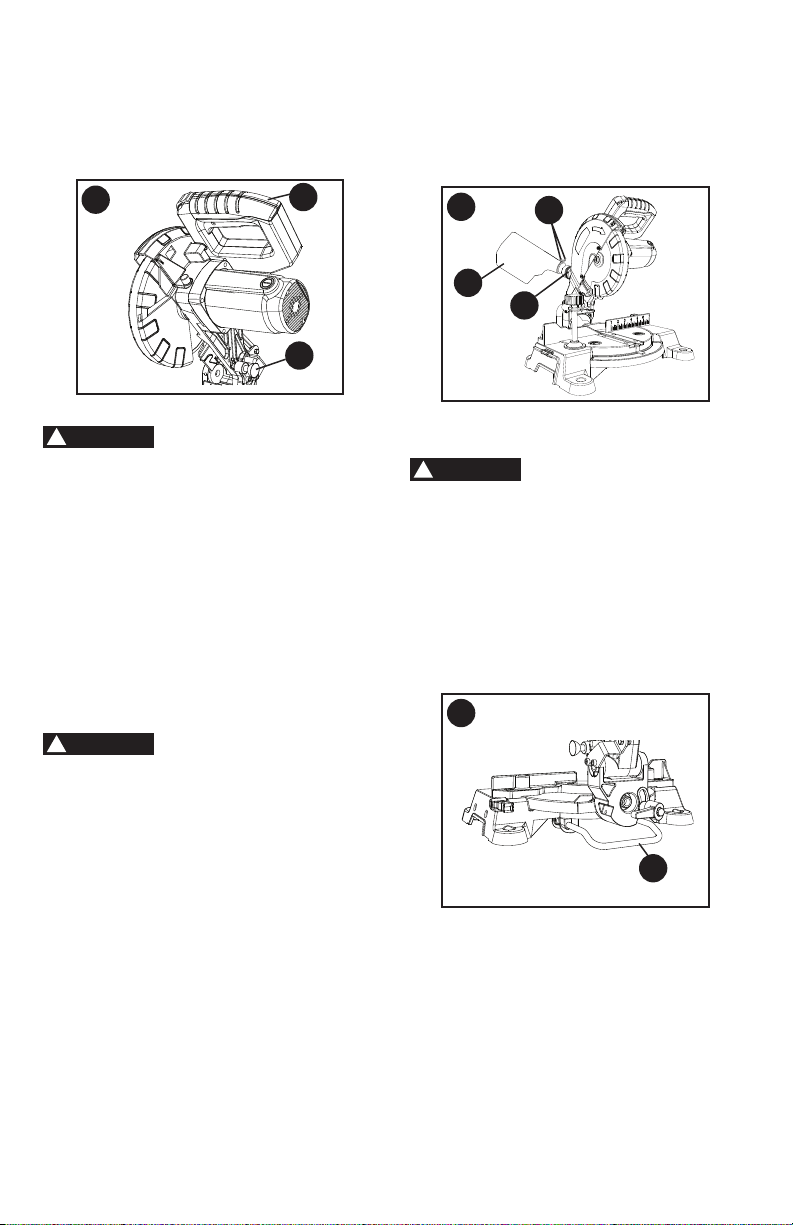
INSTALLING THE DUST BAG
(FIGURE C)
• Squeeze the metal collar wings (1) of
the dust bag (2).
• Place the dust bag neck opening
around the exhaust port (3), and
release the metal collar wings.
WARNING
!
B
2
1
WARNING
!
NOTE: To empty the dust bag, squeeze
the metal collar and remove from
exhaust port. Open zipper on underside
of bag and empty into waste container.
IMPORTANT: Check frequently and empty
bag before it gets full.
POSITIONING THE REAR SUPPORT
BRACKET PRIOR TO USE (FIGURE D)
The rear support bracket
must be extended out prior to using
the miter saw. Please follow the below
instructions before using the saw.
• The rear support bracket (1) has been
pre-installed at the factory. Prior to any
use, pull on the end of the bracket to
extend out to its full position.
NOTE: Make sure the angle of stay
is in the down position (as shown in
Figure D) for maximum support.
INSTALLING THE HOLD-DOWN CLAMP
(FIGURE E, F)
• Place the hold-down clamp (1) in one
of the mounting holes (2).
C
2
3
1
D
1
WARNING
!
14
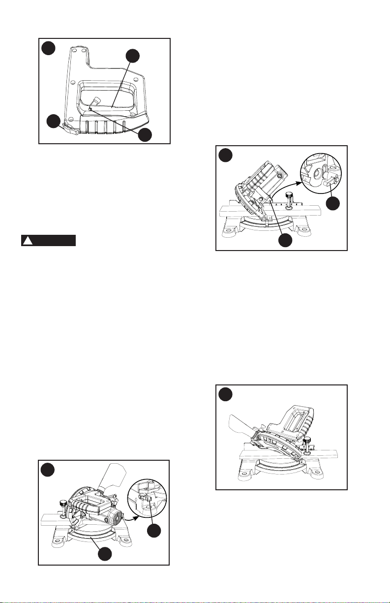
BLADE WRENCH STORAGE (FIG. G)
For convenient storage and prevention of
loss of blade wrench, there is a
holder (1) in the left side of base for
storing the blade wrench (2) when not in
use.
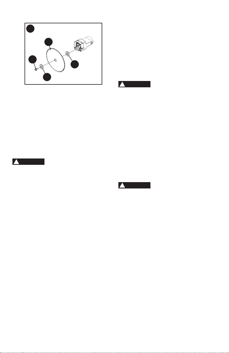
REMOVING AND INSTALLING THE
BLADE
Removing Blade (Figure H, I, J)
•
To avoid injury from an accidental
start, make sure the switch is in
the OFF position and plug is not
connected to the power source outlet.
• Only use a 7-1/4 inch diameter blade
with a 5/8 inch round arbor hole, and
no more that 7 degree hook angle.
F
2
G
1
2
E
1
2
• NEVER cut metals or masonry
products with this tool. This miter
saw is designed for use on wood
and wood-like products only.
•
Never depress the arbor lock button
while the blade is under power or
coasting.
• Unplug the saw from the outlet.
• Raise the miter saw to the upright
position.
• Loosen the cover plate screw (1) with a
Phillips screwdriver. (Figure H)
• Rotate the cover plate (2) to expose the
arbor bolt (3).
• Locate the arbor lock button (4) below
the trigger switch handle. (Figure I)
• Press the arbor lock button
(4-
Figure I
), holding it in rmly while
turning the blade clockwise. The arbor
lock button will then engage and lock
the arbor. Continue to hold the arbor
lock button, while placing the blade
wrench over the arbor bolt (3) and
turning the wrench clockwise (left-
hand threads) to loosen the arbor bolt.
(Figure J)
WARNING
!
I
4
H
1
2
3
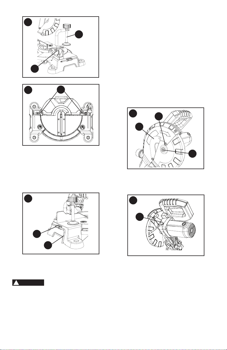
15
J
7
6
5
3
• Raise up the lower blade guard and
hold it while removing the arbor bolt (3),
outer blade collar (5), and the blade (6).
DO NOT REMOVE THE INNER BLADE
COLLAR (7).
NOTE:
Pay attention to the pieces
removed, noting their position and
direction they face. Wipe the blade
collars clean of any sawdust before
installing the new blade.
Installing Blade (Figure H, I, J)
Unplug the miter saw
before changing/installing the blade.
• Install a 7-1/4 in. blade with a 5/8 in.
arbor and no more that 7 degree hook
angle, making sure the rotation arrow
on the blade matches the clockwise
rotation arrow on the upper guard, and
the blade teeth are pointing downward.
• Raise up the lower blade guard and
hold it while placing the outer blade
collar (5) against the blade and on the
arbor. Thread the arbor bolt (3) into the
arbor in a counterclockwise direction.
(Figure J)
IMPORTANT:
Make sure the ats of the
blade collars are engaged with the ats
on the arbor shaft. Also, the at side of
the arbor collar must be placed against
the blade.
• Place the blade wrench on the arbor
bolt.
• Press the arbor lock button (4-
Figure
I), holding it in rmly while turning
the blade counterclockwise. When it
engages, continue to press the arbor
lock button in, while tightening the arbor
bolt (3) securely (left hand threads).
(Figure H)
WARNING
!
• Rotate the cover plate (2) back to its
original position until the slot in the
cover plate engages with the cover
plate screw (1). Tighten the screw with
a Phillips screwdriver.
• Verify the operation of the guard. Make
sure it does not bind or stick.
• Be sure the arbor lock button (4) is
released so the blade turns freely by
spinning the blade until the arbor lock
disengages.
(Figure I)
• To avoid injury, never use the saw
without the cover plate secure in
place. It keeps the arbor bolt from
falling out if it accidentally loosens,
and helps prevent the spinning blade
from coming off the saw. It also
keeps the guard from contacting a
spinning blade.
• Make sure the collars are clean and
properly arranged. Lower the blade
into the table and check for any
contact with the metal base or the
turn table.
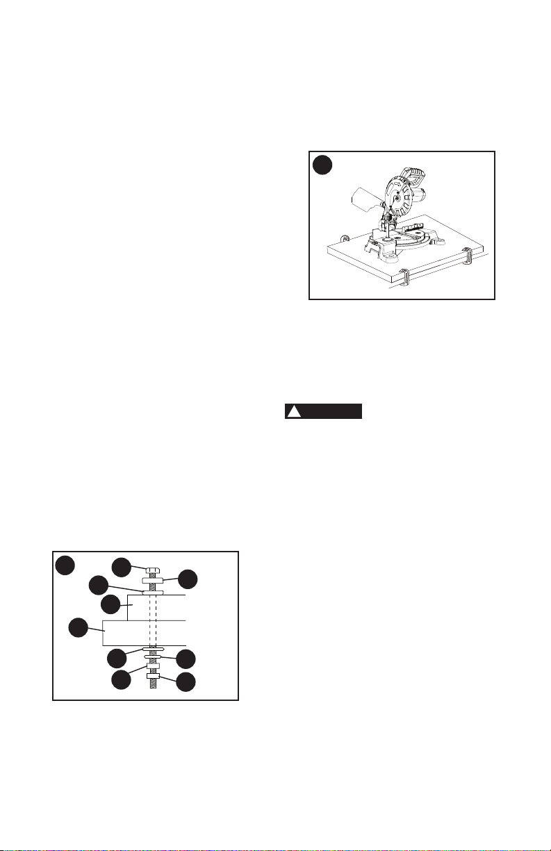
MOUNTING THE MITER SAW
(FIGURE K, L)
To avoid injury form
unexpected saw movement:
• Before moving the saw, disconnect
the power cord from the outlet, and
lock the cutting arm in the lower
position using the hold-down latch.
NOTE: The hold-down latch is for
carrying or storing the tool. It is not
to be used for holding the saw while
cutting. Lower blade and press in
hold-down latch to secure saw for
transportation or storage.
• Never carry the miter saw by the
power cord or by the switch handle.
Carrying the tool by the power
cord could cause damage to the
insulation or wire connections
resulting in electric shock or re.
• To avoid injury from ying debris,
do not allow visitors to stand behind
the saw.
WARNING
!
WARNING
!
16
• Place the saw on a rm, level work
surface where there is room for
handling and properly supporting
the workpiece.
• Support the saw on a level work
surface.
• Always bolt or clamp the saw to its
support.
• To prevent binding and inaccuracy,
be sure the mounting surface is not
warped or otherwise uneven. If the
saw rocks on the surface, place a
thin piece of material under one saw
foot until the saw sits rmly on the
mounting surface.
Mounting Instructions
•
For stationary use,
place the saw
in the desired location, directly on a
workbench where there is room for
handling and proper support of the
workpiece. The base of the saw has
four mounting holes. Bolt the base of
the miter saw (1) to the work surface (5),
using the fastening method as shown in
Figure K
.
1. Miter saw base
2. Hex head bolt
3. Rubber washer
4. Flat washer
5. Workbench
6. Flat washer
7. Lockwasher
8. Hex nut
9. Jam nut
NOTE: Mounting hardware is not included
with this tool. Bolts, nuts, washers, &
screws must be purchased separately.
•
For portable use,
place the saw on
a 3/4 in. thick piece of plywood. Bolt
the base of the miter saw securely to
the plywood using the mounting holes
on the base. Use C-clamps to clamp
this mounting board to a stable work
surface at the worksite.
(Figure L)
NOTE: If a miter saw stand is used,
please follow all instructions shown in that
product’s instructions for proper mounting.
BEVEL STOP ADJUSTMENTS
(FIGURE M, N, O)
To avoid injury from
unexpected starting or electrical shock,
make sure the trigger is released and
remove the power cord from the power
source.
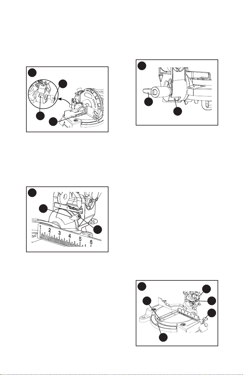
90°(0°) Bevel Adjustment (Figure M)
• Set the miter angle to zero degrees.
Loosen bevel lock handle (1) and tilt
the cutting arm completely to the right.
Tighten the bevel lock handle.
• Lower and lock the cutting head. Place
a combination square (2) on the miter
table with the ruler against the table
and the heel of the square against the
saw blade.
• If the blade is not 90°(0°) square
with the table, loosen the bevel lock
handle (1), tilt the cutting head to
the left, loosen the locknut (3) with a
10 mm wrench. Then, adjust the set
screw in the locknut (3) clockwise or
counterclockwise with a 3 mm hex key.
NOTE: The locknut is at the right rear
side of the saw base.
L
K
4
2
3
1
5
6
8
7
9
WARNING
!
17
• Tilt the cutting arm to back to the right
at 90°(0°) bevel and recheck
for alignment.
• Repeat above steps if further
adjustment is needed.
• Tighten locknut (3) and bevel lock
handle (1) when alignment is achieved.
90° Bevel Pointer Adjustment (Figure N)
• When the blade is exactly 90
o
(0
o
) to
the table, loosen the bevel pointer
screw (4) using a Phillips screwdriver.
• Adjust bevel pointer (5) to the “0” mark
on the bevel scale and retighten the
screw.
45° Bevel Adjustment (Figure O)
• Set the miter angle to zero degrees.
Loosen the bevel lock handle (1) and tilt
the cutting head completely to the left.
• Lower and lock the cutting head. Using
a combination square, check to see if
the blade angle is 45° to the table.
• If the blade is not at 45° bevel to
the table, tilt the cutting arm to the
right, loosen the locknut (5) with a
10 mm wrench. Then, adjust the set
screw in the locknut (5) clockwise or
counterclockwise with a 3 mm hex key.
NOTE: The locknut is at the left rear
side of the saw base.
M
1
2
3
• Tilt the cutting arm to the left to 45°
bevel and recheck for alignment.
• Repeat above steps until the blade is at
45° to the table.
• Tighten bevel lock handle (1) and
locknut (5) when alignment is achieved.
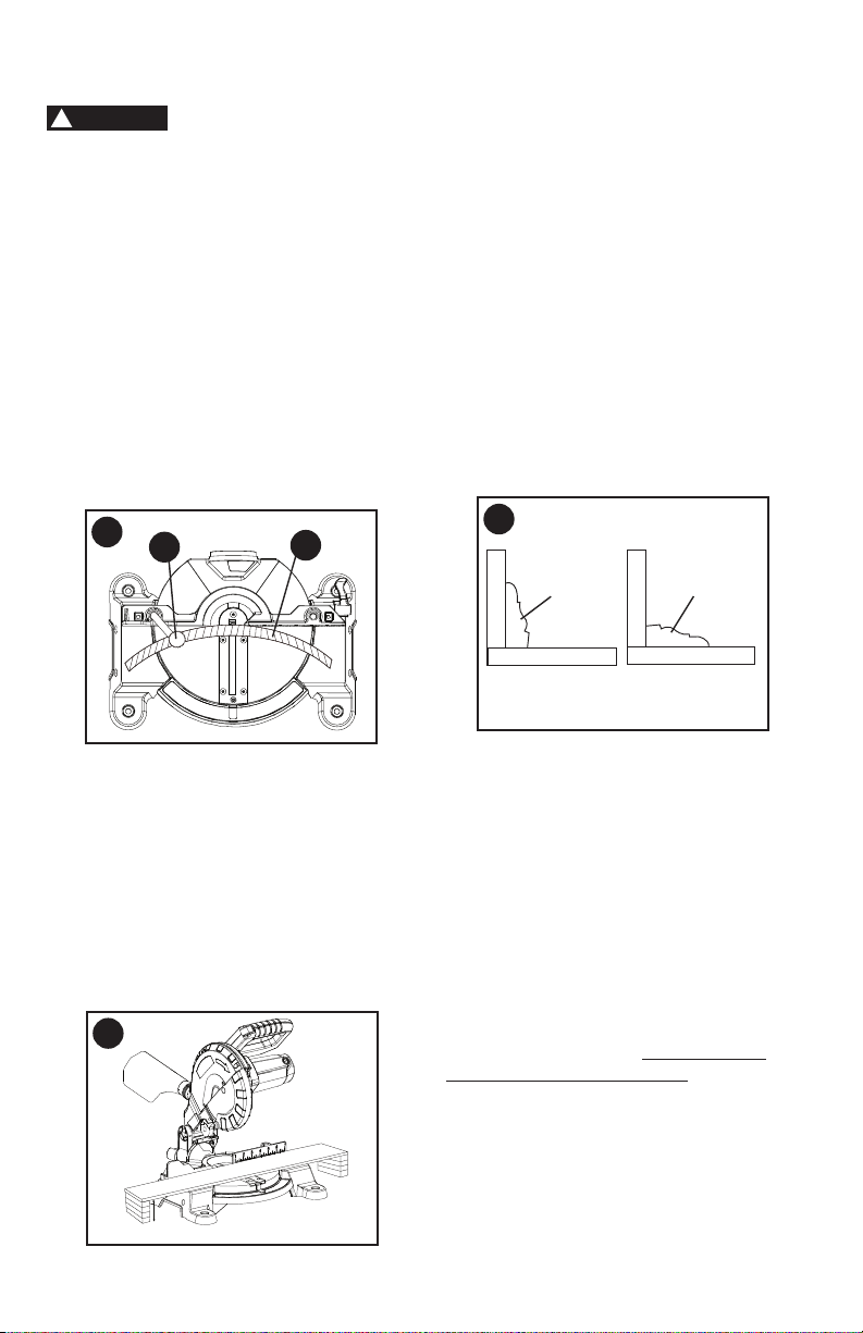
MITER ANGLE ADJUSTMENT
(FIGURE P)
The miter scale assists the user in setting
the desired miter angles from 45° left to
45° right. The miter saw table has nine
of the most common angle settings with
positive stops at 0°, 15°, 22.5°, 31.6°,
and 45°. These positive stops position
the blade at the desired angle quickly
and accurately.
• Lock the cutting head in the down
position by pushing the hold-down
latch (1) in the locking hole.
• Raise the miter table locking lever (2)
to loosen the turn table.
• Hold the base of the saw arm (3) rmly
and use it to rotate the miter table while
holding the saw base steady.
• You can quickly locate the miter angle
by the stops or clicks.
• Once you set the miter angle you want,
tighten the miter table locking lever (2)
by pushing it down.
N
5
4
O
1
5
P
4
1
3
2
5
18
• Turn the adjustment bolt (2) out
(counterclockwise) to decrease the
cutting depth or in (clockwise) to
increase the cutting depth.
• Carefully rotate the blade manually to
check for contact. Avoid touching blade
points or edges.
• Repeat until adjusted properly, and
tighten the locknut (1) to secure the
adjustment bolt (2) into position.
CAUTION
!
R
1
2
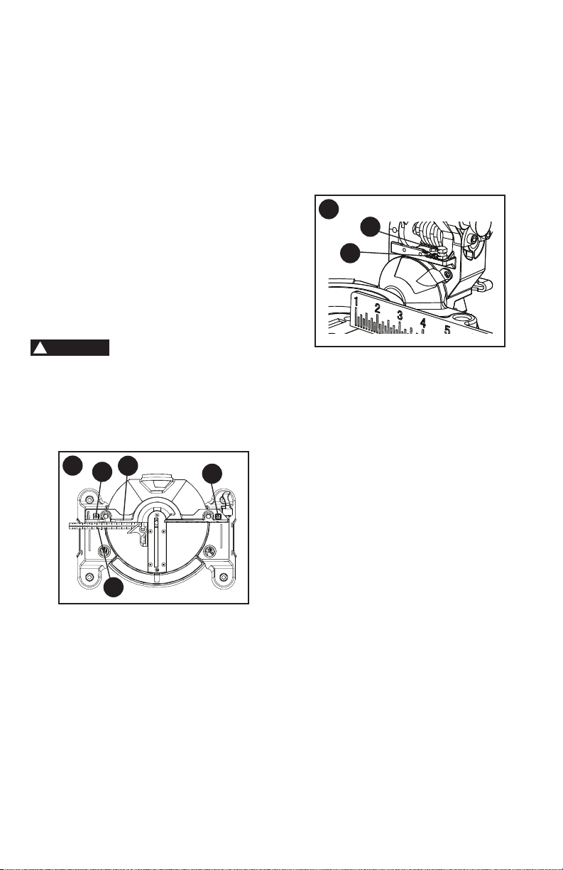
MITER ANGLE POINTER ADJUSTMENT
(FIGURE P)
• Move the table to the 0° positive stop.
• Loosen the screw (4) that holds the
pointer (5) with a Phillips screwdriver.
• Adjust the pointer (5) to the 0° mark
and retighten screw (4).
ADJUSTING FENCE SQUARENESS
(FIGURE Q)
• Set the bevel and miter angles to 0°.
• Lower the cutting arm and lock in
position.
• Using a square (1), lay the heel of the
square against the blade and the ruler
against the fence (2) as shown.
• If the blade is not 90° to the fence,
loosen the two fence locking bolts (3)
by 6 mm hex wrench.
• Adjust the fence 90° to the blade and
tighten the two fence locking bolts.
If the saw has not been
used recently, recheck blade squareness
to the fence and readjust if needed.
• After fence has been aligned, using a
scrap piece of wood, make a cut at 90°,
then check squareness on the piece.
Readjust if necessary.
ADJUSTING CUTTING DEPTH
(FIGURE R)
The maximum depth travel of the cutting
head was set at the factory. Check to see
that the blade does not extend more than
1/4 in. below the table insert, and does not
touch the control arm throat or any part of
the base or table. If the maximum depth
needs readjusting:
• To adjust the cutting depth, loosen
the lock nut (1) and the bolt (2) by two
8 mm wrenches.
Q
1
2
3
3

19
OPERATING INSTRUCTIONS
BEFORE USING THE MITER SAW
•
To reduce the risk of injury, turn
unit off and disconnect it from
power source before installing
and removing accessories, before
adjusting or when making repairs.
An accidental start-up can cause
injury.
•
To avoid mistakes that could cause
serious, permanent injury, do not
plug the tool in until the following
steps are completed:
• Completely assemble and adjust the
saw, following the instructions.
(ASSEMBLY AND ADJUSTMENTS)
• Learn the use and function of the ON/
OFF switch, upper and lower blade
guards, hold-down latch, bevel lock
handle and cover plate screws.
• Review and understand all safety
instructions and operating procedures
in this Instruction Manual.
• Review the MAINTENANCE and
TROUBLESHOOTING for your
miter saw.
• To avoid injury or possible death from
electrical shock, make sure your ngers
do not touch the plug’s metal prongs
when plugging or unplugging your
miter saw.
BEFORE EACH USE INSPECT YOUR
SAW
• Disconnect the miter saw. To avoid
injury from accidental starting, unplug
the saw before any adjustments,
including set-up and blade changes.
• Compare the direction of rotation
arrow on the guard to the direction
arrow on the blade. The blade teeth
should always point downward at the
front of the saw.
• Tighten the arbor bolt.
• Tighten the cover plate screw.
• Check for damaged parts. Check for:
• Alignment of moving parts
• Damaged electric cords
• Binding of moving parts
• Mounting holes
WARNING
!
• Function of arm return spring and
lower guard: Push the cutting arm
all the way down, then let it rise until
it stops. The lower guard should
fully close. Follow instructions in
TROUBLESHOOTING for adjustment
if necessary.
• Other conditions that may affect the
way the miter saw works.
• Keep all guards in place, in working
order and proper adjustment. If any
part of this miter saw is missing, bent,
damaged or broken in any way, or any
electrical parts do not work, turn the
saw off and unplug it.
• Replace bent, damaged, missing or
defective parts before using the saw
again.
• Maintain tools with care. Keep the
miter saw clean for best and safest
performance. Follow instructions for
lubricating. Do not put lubricants on the
blade while it is spinning.
• Remove adjusting wrench from the tool
before turning it on.
• To avoid injury from jams, slips, or
thrown pieces, use only recommended
accessories.
RECOMMENDED ACCESSORIES
• Follow the instructions that come with
the accessory. The use of improper
accessories may cause risk of injury
to persons.
• Choose the correct 7-1/4 in. diameter
blade (with a 5/8 inch round arbor hole,
and no more that 7 degree hook angle)
for the material and the type of cutting
you plan to do. Do not use thin kerf
blades.
• Make sure the blade is sharp,
undamaged and properly aligned. With
the saw unplugged, push the cutting
arm all the way down. Manually spin
the blade and check for clearance. Tilt
the power-head to a 45° bevel and
repeat the test.
• Make sure the blade and arbor collars
are clean.
• Make sure all clamps and locks are
tight and there is no excessive play in
any parts.

20
• Wear non-slip footwear.
• Tie back long hair.
• Roll long sleeves above the elbow.
• Noise levels vary widely. To avoid
possible hearing damage, wear ear
plugs when using any miter saw.
• For dusty operations, wear a dust mask
along with safety goggles.
INSPECT YOUR WORKPIECE
Make sure there are no nails or foreign
objects in the part of the workpiece
being cut.
Plan your work to avoid small pieces that
may bind, or that are too small to clamp
and get a solid grasp on. Plan the way
you will grasp the workpiece from start
to nish. Avoid awkward operations and
hand positions. Keep your hands at least
6 inches away from the blade path.
A sudden slip could cause your ngers
or hand to move into the blade.
TO ENSURE THE BLADE PATH IS
CLEAR OF OBSTRUCTIONS, ALWAYS
MAKE A DRY RUN OF THE CUT
WITHOUT POWER BEFORE MAKING
ANY CUTS ON THE WORKPIECE.
DO NOT OVER-REACH
Keep good footing and balance. Keep
your face and body to one side, out of the
line of a possible kickback. NEVER stand
in the line of the blade.
Never cut freehand:
• Brace your workpiece rmly against the
fence and table stop so it will not rock
or twist during the cut.
• Make sure there is no debris between
the workpiece and the table or fence.
• Make sure there are no gaps between
the workpiece, fence and table that will
let the workpiece shift after it is cut.
• Keep the cut off piece free to move
sideways after it is cut off. Otherwise,
it could get wedged against the blade
and thrown violently.
• Only the workpiece should be on the
saws table.
• Secure work. Use clamps or a vise to
help hold the work when it is practical.
WARNING
!
KEEP YOUR WORK AREA CLEAN
Cluttered areas and benches invite
accidents.
To avoid burns or other
re damage, never use the miter saw
near ammable liquids, vapors, or
gases.
• Plan ahead to protect your eyes,
hands, face and ears.
• Know your miter saw. Read and
understand the Instruction Manual
and labels afxed to the tool. Learn
its application and limitations as well
as the specic potential hazards
peculiar to this tool. To avoid injury from
accidental contact with moving parts,
do not do layout, assembly, or setup
work on the miter saw while any parts
are moving.
• Avoid accidental starting, make sure
the trigger switch is disengaged before
plugging the miter saw into a power
outlet.
PLAN YOUR WORK
• Use the right tool. Do not force a tool
or attachment to do a job it was not
designed to do. Use a different tool for
any workpiece that can’t be held in a
solidly braced, xed position.
This machine is not
designed for cutting masonry, masonry
products, metals. Use this miter saw to
cut only wood, or wood-like products.
Other material may shatter, bind the
blade, or create other dangers. Remove
all nails that may be in the workpiece
to prevent sparking that could cause
a re. Remove dust bag when cutting
non-ferrous metals.
DRESS FOR SAFETY
Any power tool can throw foreign
objects into the eyes. This can result
in permanent eye damage. Everyday
eyeglasses have only impact resistant
lenses and are not safety glasses.
Glasses or goggles not in compliance with
ANSI Z87.1 could seriously injure you
when they break.
• Do not wear loose clothing, gloves,
neckties or jewelry (rings, watches).
They can get caught and draw you into
moving parts.
WARNING
!
CAUTION
!
21
USE EXTRA CAUTION WITH LARGE
OR ODD SHAPED WORKPIECES
• Use extra supports (tables, sawhorses,
blocks, etc.) for workpieces large
enough to tip.
• Never use another person as a
substitute for a table extension, or as an
additional support for a workpiece that
is longer or wider than the basic miter
saw table, or to help feed, support, or
pull the workpiece.
• Do not use this saw to cut small pieces.
If the workpiece being cut would cause
your hand or ngers to be within 6 in.
of the saw blade the workpiece is too
small. Keep hands and ngers out of
the “no hands zone” area marked on
the saws table.
• When cutting odd shaped workpieces,
plan your work so it will not bind in
the blade and cause possible injury.
Molding, for example, must lie at or be
held by a xture or jig that will not let it
move when cut.
• Properly support round material such
as dowel rods, or tubing, which have
a tendency to roll when cut, causing
the blade to “bite”. This is especially
important when making angle cuts.
• NEVER tie, tape or hold the guard open
when operating the saw.
A workpiece that is
clamped, balanced and secure before
a cut may become unbalanced after
a cut is completed. An unbalanced
load may tip the saw or anything the
saw is attached to, such as a table or
workbench. When making a cut that
may become unbalanced, properly
support the workpiece and ensure the
saw is rmly bolted to a stable surface.
Personal injury may occur.
The clamp foot must
remain clamped above the base of
the saw whenever the clamp is used.
Always clamp the workpiece to the
base of the saw – not to any other part
of the work area. Ensure the clamp foot
is not clamped on the edge of the base
of the saw.
Always use a work clamp
to maintain control and reduce the risk
of workpiece damage and personal
injury.
WHEN SAW IS RUNNING
Do not allow familiarity
from frequent use of your miter saw to
result in a careless mistake. A careless
fraction of a second is enough to
cause a severe injury. Before cutting,
if the saw makes an unfamiliar noise
or vibrates, stop immediately. Turn
the saw OFF. Unplug the saw. Do not
restart until nding and correcting
the problem.
BODY AND HAND POSITION
(FIGURE S, T, U, V, W)
Never place hands near the cutting
area. Proper positioning of your
body and hands when operating the
miter saw will make cutting easier and
safer. Keep children away. Keep all
visitors at a safe distance from the miter
saw. Make sure bystanders are clear of
the saw and workpiece. Do not force the
saw. It will do the job better and safer at
its designed rate.
ALWAYS MAKE DRY RUNS
(UNPOWERED) BEFORE FINISH CUTS
SO THAT YOU CAN CHECK THE PATH
OF THE BLADE. DO NOT CROSS
HANDS, AS SHOWN IN FIGURE S, T, U
& V.
WARNING
!
WARNING
!
WARNING
!
CAUTION
!
WARNING
!
S
Proper cut
22
T
Proper cut
• Release trigger switch and wait for all
moving parts to stop before moving
your hands and raising the cutting arm.
• Unplug the miter saw.
Before freeing jammed material:
• Release trigger switch.
• Wait for all moving parts to stop.
• Unplug the miter saw.
BASIC SAW OPERATIONS
Never connect the plug
to the power source outlet until all
installations and adjustments are
completed and you have read and
understood the safety and operational
instructions.
TURNING THE SAW ON (FIGURE X)
• To reduce the likelihood of accidental
starting, a thumb activated lock-off
switch is located on top of the switch
handle. The lock-off switch (1) must
be pushed in before the trigger
switch (2) can be activated and the
miter saw started.
NOTE: To make the ON/OFF trigger switch
childproof, insert a padlock (not provided)
or chain with padlock through the hole (3)
in the trigger switch. Lock the tool’s switch
to prevent children and other unqualied
users from turning the machine on.
Starting a cut:
• Place hands at least 6 in. away on both
sides of the blade path - “no-hands
zone (1)”. (Figure W)
• Hold workpiece rmly against the fence
to prevent movement toward the blade.
• With the power switch OFF, bring the
saw blade down to the workpiece to
see the cutting path of the blade.
• Squeeze trigger switch to start saw.
• Lower blade into workpiece with a rm
downward motion.
Finishing a cut:
• Hold the cutting arm in the down
position.
V
Improper cut
U
Improper cut
WARNING
!
W
6 in. 6 in.
1
23
BEFORE LEAVING THE SAW
• Never leave tool running unattended.
Turn power OFF. Wait for all moving
parts to stop.
• Make workshop childproof. Lock the
shop. Disconnect master switches.
Store tool away from children and other
unqualied users.
To avoid injury from
materials being thrown, always unplug
the saw to avoid accidental starting, and
remove small pieces of material from
the table cavity.
MITER CUT (FIGURE Y)
• When a miter cut is required, unlock the
miter table locking lever (1).
• Hold the base of saw arm to move the
table to the desired angle.
• When the table is in the desired
position, as shown on the miter
scale (2), tighten the miter table locking
lever. The table is now locked at the
desired angle. Positive stops are
provided at 0°, 15°, 22.5°, 31.6° and 45°
left and right.
IMPORTANT: Always tighten the miter
table locking lever before performing
every cutting operation.
X
1
2
3
BEVEL CUT (FIGURE Z)
• When a bevel cut is required, loosen
the bevel lock handle (1).
• Tilt the cutting head to the desired
angle, as shown on the bevel scale (2).
• The blade can be positioned at any
angle, from a 90° straight cut (0° on the
scale) to a 45° left bevel. Tighten the
bevel lock handle (1) to lock the cutting
head in position. Positive stops are
provided at 0° and 45°.
COMPOUND CUT (FIGURE AA)
A compound cut is the combination of a
miter and a bevel cut simultaneously.
• Loosen the bevel lock handle and
position the cutting head at the desired
bevel position. Lock the bevel lock
handle. See "BEVEL CUT."
• Loosen the miter table locking lever and
position the table at the desired angle.
Lock the miter table locking lever. See
"MITER CUT."
WARNING
!
Y
2
1
Z
2
1
AA
24
CUTTING BOWED MATERIAL
(FIGURE BB)
To avoid injury from
materials being thrown, always unplug
the saw to avoid accidental starting
and remove small pieces of material
from the table cavity.
• The table insert may be removed for
this purpose, but always reattach table
insert prior to performing a cutting
operation.
• A bowed workpiece (1) must be
positioned against the fence and
secured with a clamping device (2) as
shown before cutting. Do not position
workpiece incorrectly or try to cut the
workpiece without the support of the
fence. This will cause the blade to bind
and could result in personal injury.
WORKPIECE SUPPORT (FIGURE CC)
Long pieces need extra support. The
support should be placed under the
workpiece. Keep your hand holding the
workpiece positioned 6-3/4 inches or more
away from the blade. The support must
let the workpiece lay at on the work table
during the cutting operation.
NOTE: When mounted on a at surface,
the saw table is 2-4/5 inches high.
BB
WARNING
!
CUTTING BASE MOLDING
(FIGURE DD)
Base moldings and many other moldings
can be cut on a compound miter saw.
The setup of the saw depends on molding
characteristics and application, as shown.
Perform practice cuts on scrap material to
achieve best results:
• Always make sure moldings rest rmly
against fence and table. Use hold-down,
crown molding vise or C-clamps,
whenever possible, and place tape on
the area being clamped to avoid marks.
• Reduce splintering by taping the cut
area prior to making the cut. Mark the
cut line directly on the tape.
• Splintering typically happens due to an
incorrect blade application and thinness
of the material.
NOTE: Always perform a dry run cut so
you can determine if the operation being
attempted is possible before power is
applied to the saw.
CUTTING CROWN MOLDING
(FIGURE EE, FF)
Your compound miter saw is suited for
the difcult task of cutting crown molding.
To t properly, crown molding must be
compound-miterd with extreme accuracy.
The two surfaces on a piece of crown
molding that t at against the ceiling and
wall are at angles that, when added
together equal exactly 90°.
2
1
miter at 45°, bevel at 0° miter at 0°, bevel at 45°
Miter saw table
Miter saw table
F
e
n
c
e
F
e
n
c
e
Workpiece Workpiece
DD
CC
2-4/5 in.
25
Most crown molding has a top rear
angle (the section that ts at against
the ceiling) of 52°and a bottom rear
angle (the section that ts at against
the wall) of 38°.
In order to accurately cut crown
molding for a 90° inside or outside
corner, lay the molding with its broad
back surface at on the saw table.
When setting the bevel and miter angles
for compound miters, remember that the
settings are interdependent; changing
one changes the other, as well.
Settings for standard crown molding
lying at on compound miter saw table.
Workpiece
Miter saw table
F
e
n
c
e
EE
FF
Compound cut crown moldings
Inner corner
Outside corner
IL
IR
OL
OR

26
Bevel/Miter Settings
NOTE: The chart below references a compound cut for crown molding ONLY WHEN
THE ANGLE BETWEEN THE WALLS EQUALS 90°.
KEY
BEVEL
SETTING
MITER
SETTING
TYPE OF CUT
Inside corner-Left side
IL 33.9° 31.6° Right 1. Position top of molding against fence.
2. Miter table set at RIGHT 31.6°.
3. LEFT side is nished piece.
Inside corner-Right side
IR 33.9° 31.6° Left 1. Position bottom of molding against fence.
2. Miter table set at LEFT 31.6°.
3. LEFT side is nished piece.
Outside corner-Left side
OL 33.9° 31.6° Left 1. Position bottom of molding against fence.
2. Miter table set at LEFT 31.6°.
3. RIGHT side is nished piece.
Outside corner-Right side
OR 33.9° 31.6° Right 1. Position top of molding against fence.
2. Miter table set at RIGHT 31.6°.
3. RIGHT side is nished piece.

27
CROWN MOLDING CHART
Compound Miter Saw
Miter and Bevel Angle Settings
Wall to Crown Molding Angle
52/38° Crown Molding 45/45° Crown Molding
Angle
Between
Walls
Miter
Setting
Bevel
Setting
Miter
Setting
Bevel
Setting
67 42.93 41.08 46.89 36.13
68 42.39 40.79 46.35 35.89
69 41.85 40.50 45.81 35.64
70 41.32 40.20 45.28 35.40
71 40.79 39.90 44.75 35.15
72 40.28 39.61 44.22 34.89
73 39.76 39.30 43.70 34.64
74 39.25 39.00 43.18 35.38
75 38.74 38.69 42.66 34.12
76 38.24 38.39 42.15 33.86
77 37.74 38.08 41.64 33.60
78 37.24 37.76 41.13 33.33
79 36.75 37.45 40.62 33.07
80 36.27 37.13 40.12 32.80
81 35.79 36.81 39.62 32.53
82 35.31 36.49 39.13 32.25
83 34.83 36.17 38.63 31.98
84 34.36 35.85 38.14 31.70
85 33.90 35.52 37.66 31.42
86 33.43 35.19 37.17 31.34
87 32.97 34.86 36.69 30.86
88 32.52 34.53 36.21 30.57
89 32.07 34.20 35.74 30.29
90 31.62 33.86 35.26 30.00
91 31.17 33.53 34.79 29.71
92 30.73 33.19 34.33 29.42
93 30.30 32.86 33.86 29.13
94 29.86 32.51 33.40 28.83
95 29.43 32.17 32.94 28.54
96 29.00 31.82 32.48 28.24
97 28.58 31.48 32.02 27.94
98 28.16 31.13 31.58 27.64
99 27.74 30.78 31.13 27.34
100 27.32 30.43 30.68 27.03
101 26.91 30.08 30.24 26.73
102 26.50 29.73 29.80 26.42
103 26.09 29.38 29.36 26.12
104 25.69 29.02 28.92 25.81
105 25.29 28.67 28.48 25.50
106 24.89 28.31 28.05 25.19
107 24.49 27.96 27.62 24.87
108 24.10 27.59 27.19 24.56
109 23.71 27.23 26.77 24.24
110 23.32 26.87 26.34 23.93
111 22.93 26.51 25.92 23.61
112 22.55 26.15 25.50 23.29
113 22.17 25.78 25.08 22.97
114 21.79 25.42 24.66 22.66
115 21.42 25.05 24.25 22.33
116 21.04 24.68 23.84 22.01
117 20.67 24.31 23.43 21.68
118 20.30 23.94 23.02 21.36
119 19.93 23.57 22.61 21.03
120 19.57 23.20 22.21 20.70
121 19.20 22.83 21.80 20.38
122 18.84 22.46 21.40 20.05
123 18.48 22.09 21.00 19.72
52/38° Crown Molding 45/45° Crown Molding
Angle
Between
Walls
Miter
Setting
Bevel
Setting
Miter
Setting
Bevel
Setting
124 18.13 21.71 20.61 19.39
125 17.77 21.34 20.21 19.06
126 17.42 20.96 19.81 18.72
127 17.06 20.59 19.42 18.39
128 16.71 20.21 19.03 18.06
129 16.37 19.83 18.64 17.72
130 16.02 19.45 18.25 17.39
131 15.67 19.07 17.86 17.05
132 15.33 18.69 17.48 16.71
133 14.99 18.31 17.09 16.38
134 14.66 17.93 16.71 16.04
135 14.30 17.55 16.32 15.70
136 13.97 17.17 15.94 15.36
137 13.63 16.79 15.56 15.02
138 13.30 16.40 15.19 14.62
139 12.96 16.02 14.81 14.34
140 12.63 15.64 14.43 14.00
141 12.30 15.25 14.06 13.65
142 11.97 14.87 13.68 13.31
143 11.64 14.48 13.31 12.97
144 11.31 14.09 12.94 12.62
145 10.99 13.71 12.57 12.29
146 10.66 13.32 12.20 11.93
147 10.34 12.93 11.83 11.59
148 10.01 12.54 11.46 11.24
149 9.69 12.16 11.09 10.89
150 9.37 11.77 10.73 10.55
151 9.05 11.38 10.36 10.20
152 8.73 10.99 10.00 9.85
153 8.41 10.60 9.63 9.50
154 8.09 10.21 9.27 9.15
155 7.77 9.82 8.91 8.80
156 7.46 9.43 8.55 8.45
157 7.14 9.04 8.19 8.10
158 6.82 8.65 7.83 7.75
159 6.51 8.26 7.47 7.40
160 6.20 7.86 7.11 7.05
161 5.88 7.47 6.75 6.70
162 5.57 7.08 6.39 6.35
163 5.26 6.69 6.03 6.00
164 4.95 6.30 5.68 5.65
165 4.63 5.90 5.32 5.30
166 4.32 5.51 4.96 4.94
167 4.01 5.12 4.61 4.59
168 3.70 4.72 4.25 4.24
169 3.39 4.33 3.90 3.89
170 3.08 3.94 3.54 3.53
171 2.77 3.54 3.19 3.10
172 2.47 3.15 2.83 2.83
173 2.15 2.75 2.48 2.47
174 1.85 2.36 2.12 2.12
175 1.54 1.97 1.77 1.77
176 1.23 1.58 1.41 1.41
177 0.92 1.18 1.06 1.06
178 0.62 0.79 0.71 0.71
179 0.31 0.39 0.35 0.35
28
Replace for the other side. To reassemble
reverse the procedure. The ears on the
metal end of the assembly go in the same
hole the carbon part ts into. Tighten the
cap snugly, but do not overtighten. Repeat
for the carbon brush located on the other
side of motor.
NOTE: To reinstall the same brushes,
rst make sure the brushes go back in
exactly the way they came out. This will
avoid a break-in period that reduces motor
performance and increases wear.
LOWER BLADE GUARD
Do not use the saw without the lower
blade guard. The lower blade guard is
attached to the saw for your protection.
Should the lower guard become
damaged, do not use the saw until the
damaged guard has been replaced.
Develop a regular check to make sure
the lower guard is working properly.
Clean the lower guard of any dust or
buildup with a damp cloth.
• When cleaning the lower guard,
unplug the saw from the power
source receptacle to avoid
unexpected startup.
•
Do not use solvents on the guard.
They could make the plastic “cloudy”
and brittle.
SAWDUST
Periodically, sawdust will accumulate
under the work table and base. This
could cause difculty in the movement
of the worktable when setting up
a miter cut. Frequently blow out or
vacuum up the sawdust.
MAINTENANCE
•
To reduce the risk of injury, turn unit
off and disconnect it from power
source before installing and removing
accessories, before adjusting or
when making repairs. An accidental
start-up can cause injury.
•
DO NOT touch the sharp points on
the blade with ngers or hands while
performing any maintenance.
•
To avoid injury, never put lubricants
on the blade while it is spinning.
•
DO NOT use lubricants or cleaners
(particularly spray or aerosol) in
the vicinity of the plastic guard.
The plastic material used in the
guard is subject to attack by certain
chemicals.
•
To avoid re or toxic reaction, never
use gasoline, naphtha acetone,
lacquer thinner or similar highly
volatile solvents to clean the miter
saw.
•
To avoid injury from unexpected
starting or electrical shock, unplug
the power cord before working on
the saw.
•
For your safety, this saw is double
insulated. To avoid electrical shock,
re or injury, use only parts identical
to those identied in the parts list.
Reassemble exactly as the original
assembly to avoid electrical shock.
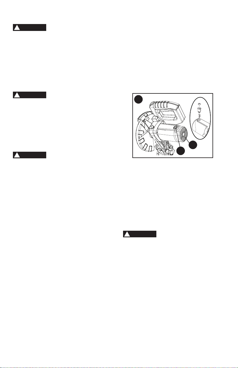
REPLACING CARBON BRUSHES
(FIGURE GG)
The carbon brushes furnished will last
approximately 50 hours of running time,
or 10,000 ON/OFF cycles. Replace both
carbon brushes when either has less than
1/4 in. length of carbon remaining, or if
the spring or wire is damaged or burned.
To inspect or replace brushes, rst unplug
the saw. Then remove the plastic cap (1)
on the side of the motor (2). Remove the
cap cautiously, because it is springloaded.
Then pull out the brush and replace.
DANGER
!
WARNING
!
WARNING
!
2
1
WARNING
!
GG
29
To empty the dust bag, remove the
sawdust bag from the dust collection
port. Open the zipper on the sawdust
bag and empty out the sawdust inside.
Close the zipper and reinstall the dust
bag as described on page 13.
Wear proper eye
protection to keep debris from entering
eyes when removing sawdust from unit.
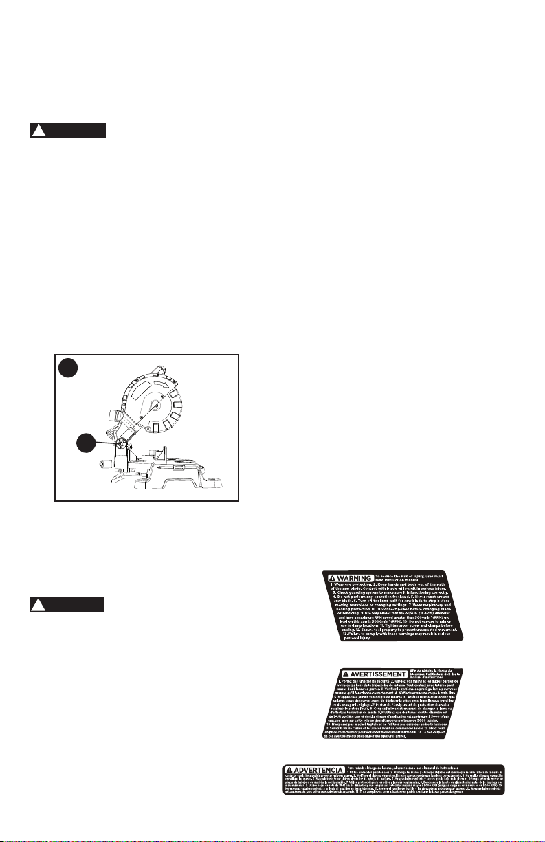
LUBRICATION (FIGURE HH)
All the motor bearings in this tool are
lubricated with a sufcient amount of
high grade lubricant for the life of the
unit under normal operating conditions;
therefore, no further bearing lubrication
is required.
Lubricate the following as necessary:
Chop pivot (1):
Apply light machine oil to
points indicated in illustration.
ACCESSORIES
Recommended accessories for use with
your tool are available from your local
dealer or authorized service center. If you
need assistance regarding accessories,
please call: 1-844-437-5095.
The use of any accessory
not recommended for use with this tool
could be hazardous.
SERVICE INFORMATION
All Black+Decker Service Centers are
staffed with trained personnel to provide
customers with efcient and reliable
power tool service. Whether you need
technical advice, repair or genuine
factory replacement parts, contact the
Black+Decker location nearest you. To nd
your local service location, call: 1-844-437-
5095 or visit www.blackanddecker.com.
WARNING
!
FULL TWO-YEAR HOME USE
WARRANTY
Black+Decker warrants this product for
two years against any defects in material
or workmanship. The defective product
will be replaced or repaired at no charge
in either of two ways.
The rst, which will result in exchanges
only, is to return the product to the retailer
from whom it was purchased (provided
that the store is a participating retailer).
Returns should be made within the
time period of the retailer’s policy for
exchanges (usually 30 to 90 days after
the sale). Proof of purchase may be
required. Please check with the retailer
for their specic return policy regarding
returns that are beyond the time set for
exchanges.
The second option is to take or send
the product (prepaid) to a Black+Decker
owned or authorized Service Center for
repair or replacement at our option. Proof
of purchase may be required.
This warranty does not apply to
accessories. This warranty gives you
specic legal rights and you may have
other rights which vary from state to state
or province to province. Should you have
any questions, contact the manager
of your nearest Black+Decker Service
Center. This product is not intended for
commercial use.
FREE WARNING LABEL
REPLACEMENT: If your warning labels
become illegible or are missing, call
1-844-437-5095 for a free replacement.
WARNING
!
1
HH

30
TROUBLESHOOTING
SAW OPERATION
Problem Possible Cause Possible Solution
• Blade hits
table.
• Misalignment. • See ADJUSTMENT -Setting
Cutting Depth section.
• Angle of cut
not accurate.
Can not adjust
miter.
• Miter table unlocked.
• Sawdust under table.
• See OPERATION - Miter Angle
Adjustment section.
• Vacuum or blow out dust. WEAR
EYE PROTECTION.
• Cutting arm
wobbles.
• Loose pivot points. • Contact Service Center.
• Cutting arm
will not fully
raise, or blade
guard won’t
fully close.
• Pivot spring not replaced
properly after service.
• Sawdust build-up.
• Clean and lubricate moving parts.
• Contact Service Center.
• Blade binds,
jams, burns
wood.
• Improper operation.
• Dull or warped blade.
• Improper blade size.
• Wood is moving during cut.
• See BASIC SAW OPERATION
section.
• Replace or sharpen blade.
• Replace with 7-1/4 in. diameter
blade.
• Use hold-down clamp to secure
workpiece to table.
• Saw vibrates
or shakes.
• Saw blade not round / damaged
/ loose.
• Arbor bolt loose.
• Replace blade.
• Tighten arbor bolt.
LATIN AMERICA: This warranty does not
apply to products sold in Latin America.
For products sold in Latin America, check
country specic warranty information
contained in the packaging, call the local
company or see the website for warranty
information.

31
MOTOR
Problem Possible Cause Possible Solution
• Motor does
not start.
• Limit switch failure
• Brush worn.
• Fuse blown or circuit breaker
tripped on home panel.
• Replace limit switch.
• Replace brushes. See
MAINTENANCE section.
• Verify there is electrical power at
the outlet.
• Brush spark
when switch
released.
• Brush worn.
• Other.
• Replace Brushes. See
MAINTENANCE section.
• Contact Service Center.
For assistance with your product, visit our website www.blackanddecker.com for the
location of the service center nearest you or call the BLACK+DECKER help line at
1-844-437-5095.
BLACK+DECKER and the BLACK+DECKER logo are registered trademarks of
BLACK+DECKER and are used under license. All rights reserved.
Imported by
Power Tool Specialists, Inc.
684 Huey Road
Rock Hill, SC 29730 U.S.A.
TM

32
PARTS LIST
7-1/4 IN. MITER SAW MODEL NO. M1850BD TYPE 2
PARTS LIST FOR MITER SAW - (1)
I.D.
Description Size Q’ty
I.D.
Description Size Q’ty
X6VM BAG-DUST ASS'Y 1 X6WU COMPRESSION SPRING 1
X6VN PC-GUARD ASS’Y 1 X6WV C-RING ø8 1
X6VR VISE ASS'Y 1 X6WW LOCATOR PIN 1
X6VW O-RING ø10*ø1.9 1 X6WX HANDLE 1
X6VX CR. RE. PAN HD. SCREW M5*8 2 X6WY BALL BEARING 1
X6VY RING ø6 1 X6WZ FLOW GUIDE 1
X6VZ ROLLING WHEEL 1 X6X0 CR. RE. PAN HD. SCREW M5*25 1
X6W0 SHAFT SLEEVE 1 X6X1 COVER 1
X6W1 SPRING WASHER ø8 1 X6X2 ARM 1
X6W2 CR. RE. PAN HD. TAPPING 6 X6X3 INSTRUCTION MANUAL 1
SCREW X6X4 DAMPER 1
X6W4 MOTOR HANDLE (TOP) 1 X6X5 HOUSING 1
X6W6 TRIGGER 1 X6X6 CR. RE. PAN HD. SCREW M5*16 3
X6W7 LIMIT SWITCH 1 X6X7 TRADEMARK LABEL 1
X6W8 VISE BEARING 1 X6X8 COVER PLATE 1
X6W9 ROCKER SWITCH 1 X6X9 CR. RE. COUNT HD. SCREW M5 1
X6WA CR. RE. PAN HD. SCREW M5*12 2 X6XB HEX. SOC. HD. CAP BOLT M6*16 1
X6WB CR. RE. PAN HD. TAPPING ST3.9*14 2 X6XC FOLLOWER PLATE 1
SCREW X6XD BLADE 1
X6WC CORD CLAMP 1 X6XE FOLLOWER PLATE 1
X6WD POWER CABLE 1 X6XF RING ø38 1
X6WE GUARD-CORD 1 X6XG PC-GUARD 1
X6WF MOTOR HANDLE (DOWN) 1 X6XH SPRING 1
X6WG LABEL 1 X6XJ CR. RE. COUNT HD. SCREW M5*12 2
X6WH BRUSH COVER 2 X6XK BEARING SEAT 1
X6WJ CARBON BRUSH ASS'Y 2 X6XL BALL BEARING 1
X6WK BRUSH HOLDER ASS'Y 2 X6XM RING ø32 1
X6WL FLAT WASHER ø5 6 X6XN CUTTER SHAFT 1
X6WM CR. RE. PAN HD. SCREW M5*35 4 X6XP PARALLEL KEY 4*12 1
X6WN MOTOR COVER 1 X6XQ HELIX GEAR 1
X6WP TRADEMARK LABEL 1 X6XR BRAKE BLOCK 1
X6WQ BALL BEARING 1 X6XS NEEDLE ROLLER BEARING 1
X6WR STATOR CORE ASS'Y 1 X6XT HANDLE 1
X6WS CR. RE. PAN HD. TAPPING 2 X6XU WARNING LABEL 1
SCREW X6XV HEX. HD. BOLT M5*16 1
X6WT ARMATURE ASS'Y 1 X6XW FLAT WASHER ø12*ø24*2.5 2

33
7-1/4 IN. MITER SAW MODEL NO. M1850BD TYPE 2
PARTS LIST FOR MITER SAW - (2)
I.D.
Description Size Q’ty
I.D.
Description Size Q’ty
X6XX LOCK NUT M12 1 X6YQ HEX. SOC. HD. CAP BOLT 1
X6XY CR. RE. COUNT HD. SCREW 1 X6YR TILT POINTER 1
X6XZ LOCK NUT M5 1 X6YS TABLE 1
X6Y0 SUPPORT PLATE 1 X6YY FENCE 1
X6Y1 HEX. SOC. HD. CAP BOLT M5*12 2 X6YZ HEX. SOC. HD. CAP BOLT M8*25 2
X6Y2 SPRING WASHER ø5 6 X6Z0 FLAT WASHER ø8 2
X6Y3 SHAFT SLEEVE 1 X6Z1 SHAFT SLEEVE 4
X6Y4 CR. RE. COUNT HD. SCREW 1 X6Z2 SHAFT SLEEVE 2
X6Y5 ANGLE PEGULATOR 1 X6Z3 BRACING PLATE 1
X6Y6 HANDLE 1 X6Z4 EXTENTION WING 1
X6Y7 LOCATOR PIN 1 X6Z5 CR. RE. PAN HD. SCREW M4*8 5
X6Y8 TILT POINTER 1 X6Z6 STEEL BALL ø10 1
X6Y9 HEX. NUT M5 1 X6Z7 SPRING 2
X6YA ANCHOR BLOCK 1 X6Z8 HEX. SOC. HD. CAP BOLT M10*10 1
X6YB BOLT M12 1 X6Z9 WARNING LABEL 1
X6YC CR. RE. PAN HD. SCREW M5*14 1 X6ZA BASE 1
X6YD CR. RE. PAN HD. SCREW M5*8 2 X6ZB FOOT 4
X6YE BOLT 1 X6ZC TILTING SCALE 1
X6YF TILTING SCALE 1 X6ZD FLAT WASHER ø10*ø20*2 1
X6YG HEX. SOC. HD. CAP BOLT M6*8 1 X6ZE LOCK NUT M10 1
X6YH HEX. SOC. HD. CAP BOLT M6*14 2 X6ZF WARNING LABEL 1
X6YJ HEX. NUT M6 2 X6ZG SCREW 1
X6YK CR. RE. COUNT HD. SCREW 1 X6ZH HANDLE BAR ASS'Y 1
X6YL TORSION SPRING 1 X6ZJ COMPRESSION SPRING 1
X6YM SHAFT-PIVOT 1 X6ZK CR. RE. COUNT HD. SCREW 1
X6YN CR. RE. COUNT HD. SCREW M4*8 5 X7MZ BLADE WRENCH HOLDER 1
X6YP TABLE INSERT 1 X7MY BLADE WRENCH 1
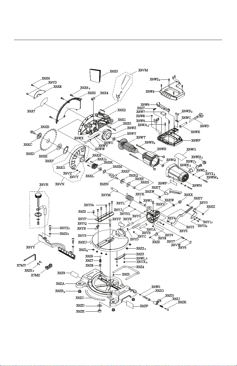
34
7-1/4 IN. MITER SAW
SCHEMATIC
MODEL NO. M1850BD TYPE 2