Loading ...
Loading ...
Loading ...
KBF / KBF-UL + KMF (E6) 04/2020 page 35/163
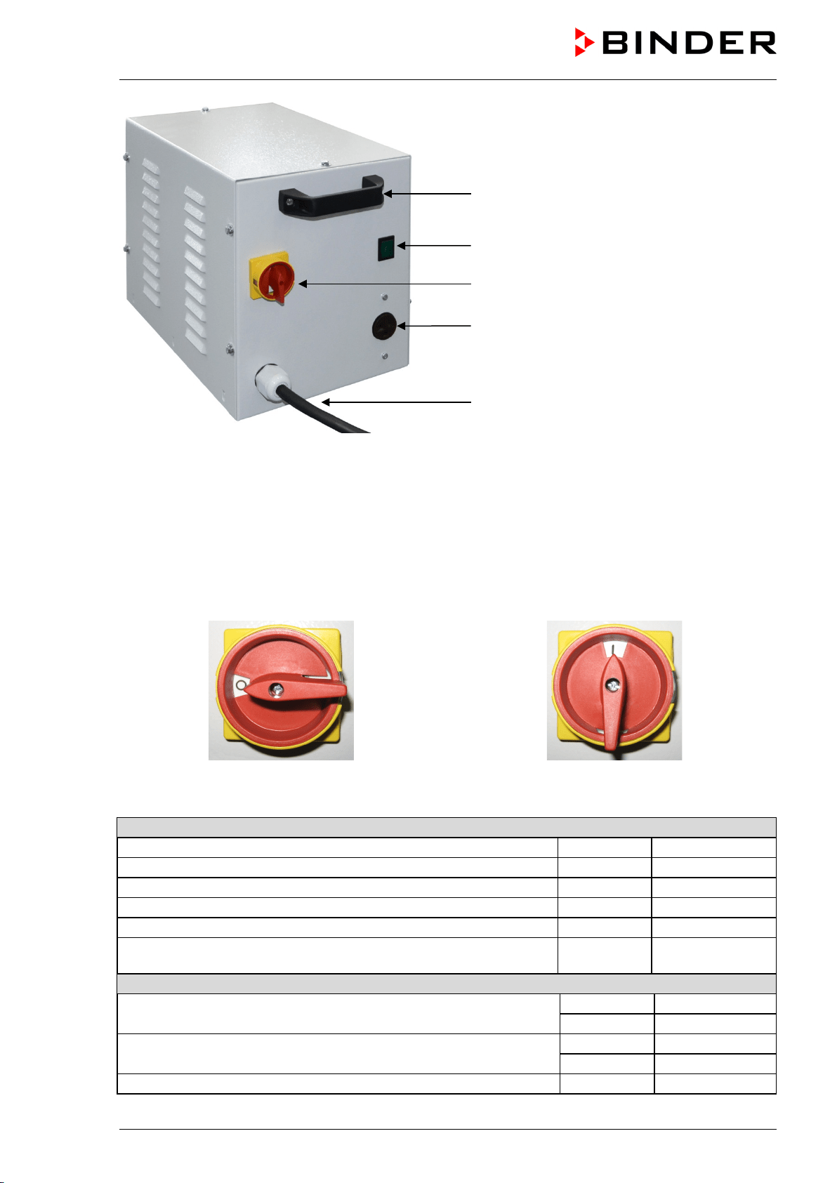
(A) Carrying handle
(B) Pilot lamp (green)
(C) Power switch
(D) Connection socket for KBF
(E) Power cable
Figure 12: Voltage changer (front)
To establish the electrical connection of the constant climate chamber with the voltage changer, proceed
in the following order:
1. Connect the power cable of the constant climate chamber to the connection socket (D) of the voltage
changer
2. Establish the power connection of the voltage changer. The socket must provide a protective conduc-
tor.
3. Turn on the voltage changer at the power switch (C) (position “I”). The green pilot lamp (B) lights up.
4. Turn on the constant climate chamber with the main power switch (1) in the lateral control panel
Position “0” = off Position “I” = on
Figure 13: Power switch of the voltage changer
Dimensions of the voltage changer
Width
mm
255
Depth (without door handles)
mm
360
Depth (incl. cable and door handles)
mm
450
Height
mm
300
Length of the connection cable to wall socket
mm
172
Lateral wall clearance of the constant climate chamber
to set up the voltage changer (minimum)
mm 400
Electrical connection data of the voltage changer
Input side
V
115
A
26,9
Output side (to the chamber)
V
214
A
13,0
Power frequency
Hz
50 / 60
(A)
(B)
(C)
(D)
(E)
Loading ...
Loading ...
Loading ...