Loading ...
Loading ...
Loading ...
WARNING – SERVICING TO BE CARRIED OUT ONLY BY AN AUTHORISED PERSON
Disconnect from electricity before servicing. Check appliance is safe when you have nished.
29
8. Servicing
Disconnect the cooker from the electricity supply
before servicing, particularly before removing any
of the following: control panel, side panels, ceramic
hob, or any of the electrical components or cover
boxes.
Before reconnection, check that the appliance is
electrically safe.
1. To Remove a Side Panel
Disconnect from electricity supply.
Pull the cooker forward. Pull o the control panel end caps
at each end of the panel (Fig.8-1). Remove the xing screws
under the end caps.
Remove the retaining screws for each panel (one at the front,
two at the rear, and one at each lower front corner of the side
panels).
Reassemble in reverse order.
2. To Lift up the Ceramic Hob
Disconnect from electricity supply.
Pull o the push t control panel end caps at each end and
remove the end xing screws under the end cap.
Remove the lower front retaining screws (one each side)
situated beneath the lower edge at the front corners of the
side panels.
Swing the side panels to gain access to the hob xing screws
(1 each side) at the top front of the side uprights.
Remove these screws.
Lift up the ceramic hob at the front and prop into position
with a non-metallic prop.
CAUTION: The ceramic hob material is much more sensitive
to scratches on the underside than the top.
Take care not to touch or scratch the underside of the ceramic
as this will weaken the material and cause the top to shatter.
3. To Remove the Control Panel
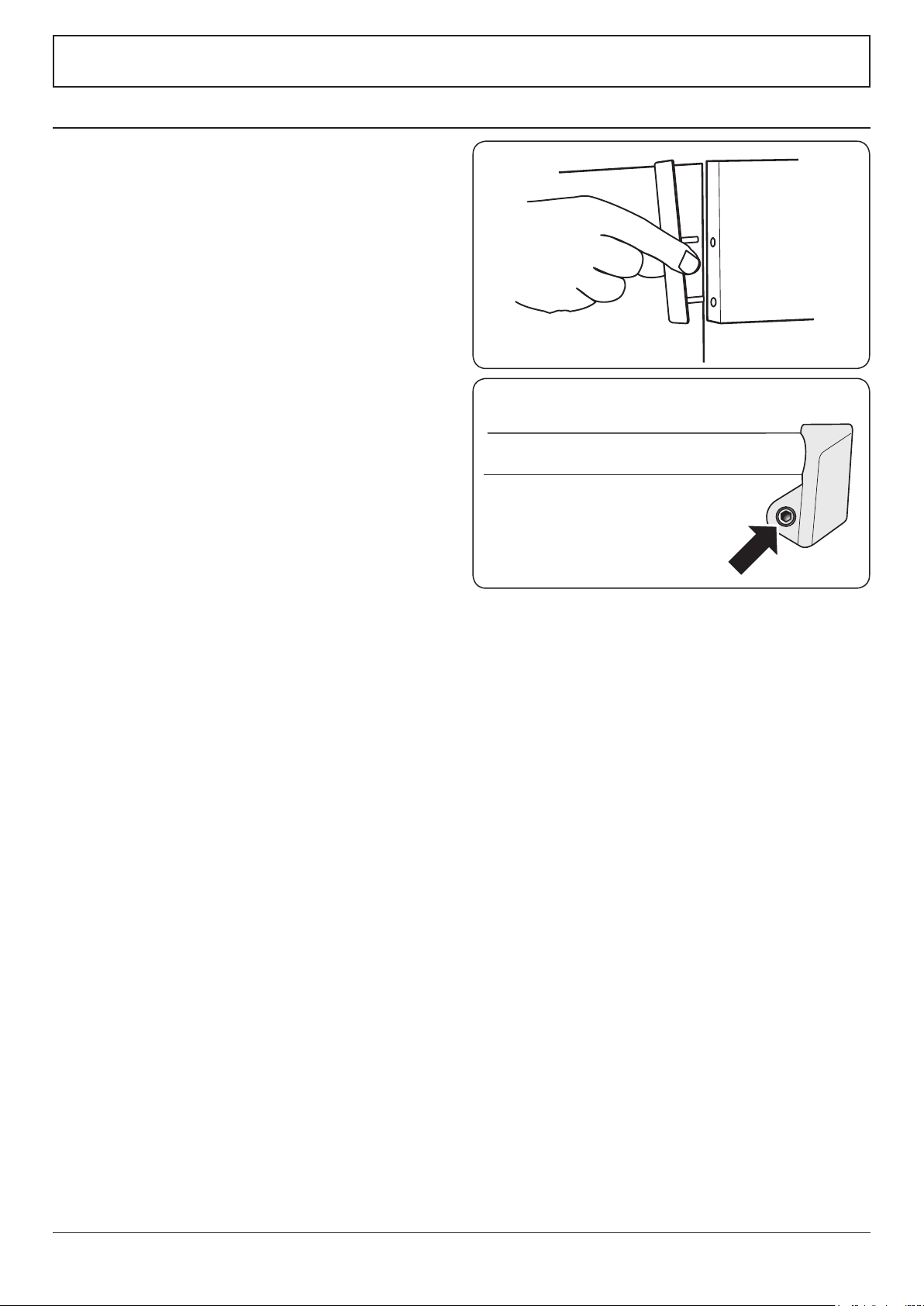
Classic only: Remove the handrail by unscrewing the 2 end
bracket xing screws (Fig.8-2).
Pull o the control panel end caps at each end of the panel
(Fig.8-1). Remove the xing screws under the end caps.
Pull o all the control knobs. Open the grill and right-hand
oven door and remove the control panel xing screws
underneath the control panel. The screws directly below the
clock are for the clock xing bracket, so do not remove them
at this stage.
Lift the control panel, pull forward and disconnect the wiring
from the rear.
Reassemble in reverse order. When replacing leads, refer to
the wiring diagram in this manual. Check the operation of the
timer.
ArtNo.210-0008 - Classic
Removing the end caps
Fig.8-1
ArtNo.210-0009 - Classic
removing the handles
Fig.8-2
Loading ...
Loading ...
Loading ...