Loading ...
Loading ...
Loading ...
INSTALLATION
Check the appliance is electrically safe when you have nished.
27
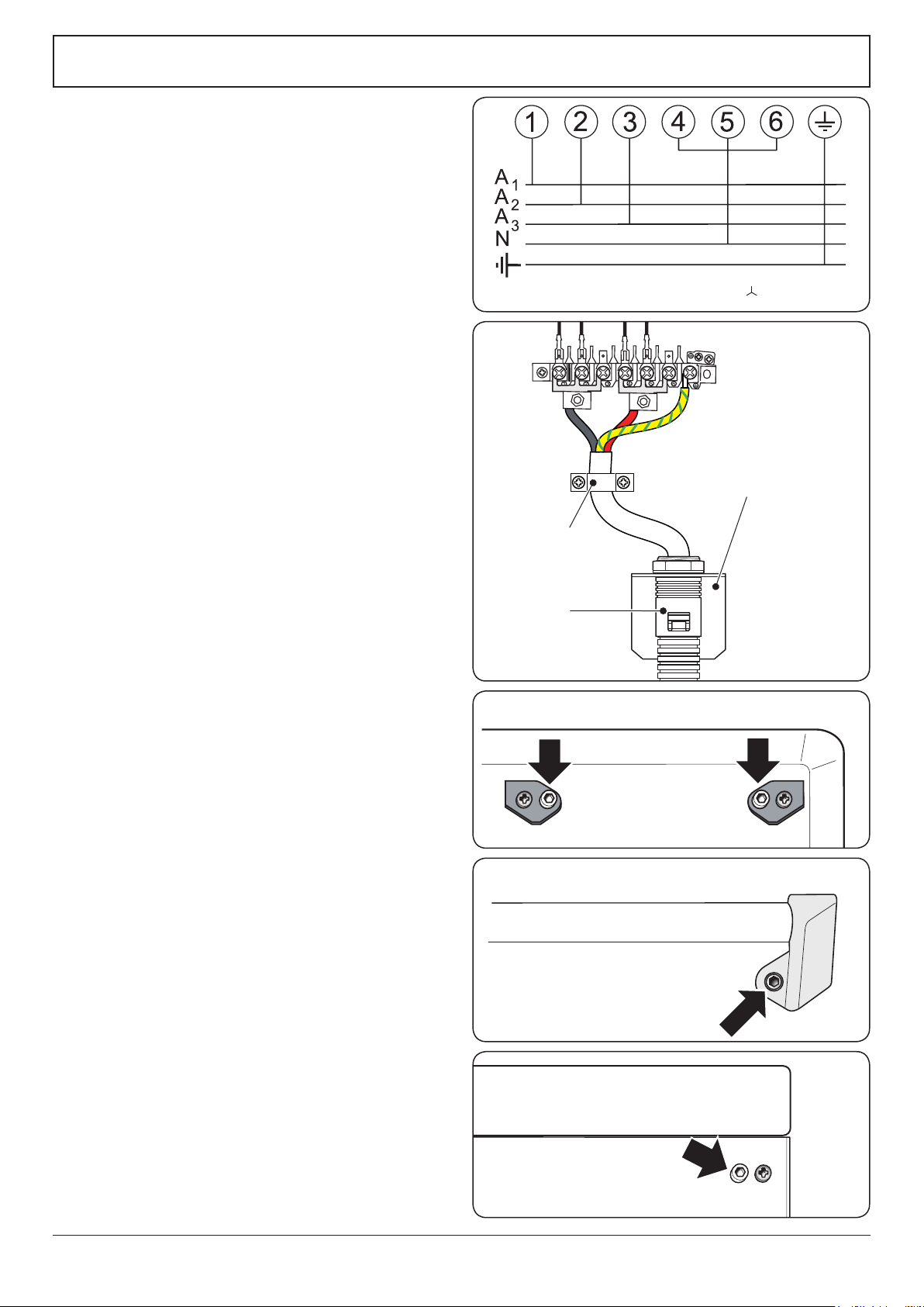
ArtNo.132-0002 - 3 phase 240/415Vac 50Hz
3-phase 240/415 V
AC
50 Hz
Fig.7-10
ArtNo.132-0005 - Fixed wiring connection 2 (AUS)
Mains terminal
Fixing bracket for
conduit connection
Conduit
Cable clamp
A N
Fig.7-11
Ret the rear cover.
Repositioning the Cooker following
Connection
If you need to move the cooker once it has been connected,
make sure it is switched o at the supply switch before
gripping under the fascia panel and lifting the front of the
cooker slightly (Fig.7-5). Check behind the cooker to ensure
that the electricity cable is not caught. As you progress,
always ensure that the cable has sucient slack to allow the
cooker to move.
Make sure to release the stability chain as you ease the
cooker out. Do not forget to ret it when you replace the
cooker.
When you replace the cooker, check behind it again once
more to ensure that the electricity cable is not caught or
trapped.
Hob Check
Check each cooking zone in turn. Be sure to use pans of the
correct size and material.
Grill Check
Turn on the grill control and check that the grill heats up.
Oven Check
Set the clock as described earlier, and then turn on the ovens.
Check the oven fans start to turn and that the ovens heat up.
Fitting the Handles and Handrail (Classic
model only)
Remove the 4mm Allen screws from the doors (Fig.7-12).
Fit the door handles and secure using the 4mm screws
(Fig.7-13).
The handles should be above the xings.
Remove the 4mm Allen screws from the top corners of the
fascia (Fig.7-14). Fit the front handrail in position and secure
using the 4mm screws.
ArtNo.215-0026 - Handle gaskets fixed
ArtNo.210-0009 - Classic
removing the handles
Art No 215-0028 - Handrail fascia fixings
Fig.7-12
Fig.7-13
Fig.7-14
Loading ...
Loading ...
Loading ...