Loading ...
Loading ...
Loading ...
7
ENGLISH
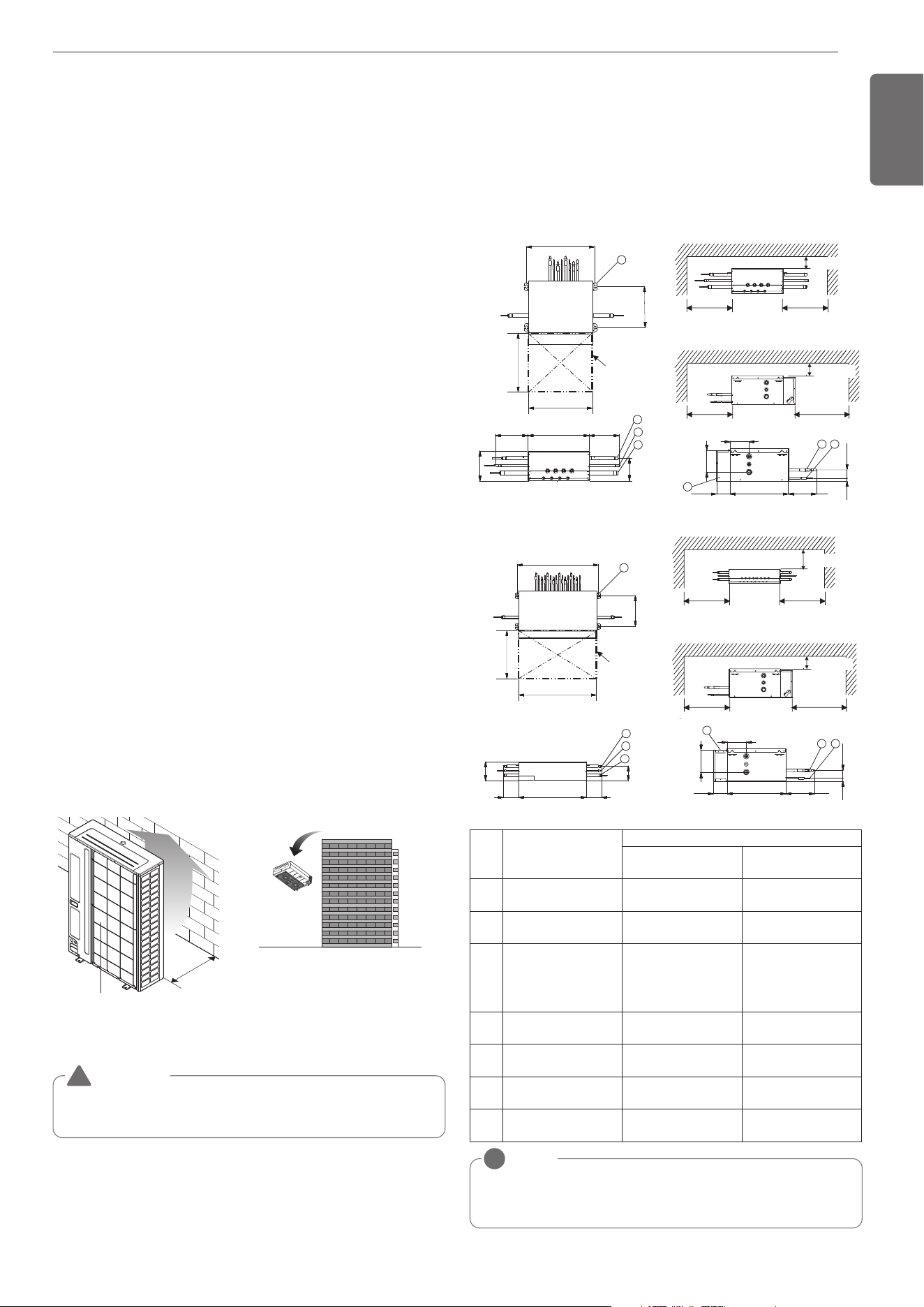
Air inlet grille
500mm
(19-11/16inch)
[Unit:mm(inch)]
Turn the air outlet side toward the
building's wall, fence or windbreak screen.
For detailed instructions on installing the HR Unit, see the installation
manual included with the HR Unit.
WARNING
Fix the outdoor unit firmly with anchor bolt or it may fall and hurt
people. (refer to ‘Foundation for installation’)
!
SELECT THE BEST LOCATION
Select space for installing outdoor unit, which will meet the following
conditions:
• No direct thermal radiation from other heat sources
• No possibility of annoying neighbors by noise from unit
• No exposition to strong wind
• With strength which bears weight of unit
• Note that drain flows out of unit when heating
• With space for air passage and service work shown next
• Because of the possibility of fire, do not install unit to the space
where generation, inflow, stagnation, and leakage of combustible
gas is expected.
• Avoid unit installation in a place where acidic solution and spray (sul-
fur) are often used.
• Do not use unit under any special environment where oil, steam and
sulfuric gas exist.
• It is recommended to fence round the outdoor unit in order to pre-
vent any person or animal from accessing the outdoor unit.
• If installation site is area of heavy snowfall, then the following direc-
tions should be observed.
- Make the foundation as high as possible.
- Fit a snow protection hood.
Select installation location considering following conditions to avoid
bad condition when additionally performing defrost operation.
• Install the outdoor unit at a place well ventilated and having a lot of
sunshine in case of installing the product at a place with a high hu-
midity in winter (near beach, coast, lake, etc).
(Ex) Rooftop where sunshine always shines.
• Performance of heating will be reduced and preheat time of the in-
door unit may be lengthened in case of installing the outdoor unit in
winter at following location:
- Shade position with a narrow space
- Location with much moisture in neighboring floor.
- Location with much humidity around.
- Location where ventilation is good. It is recommended to install the
outdoor unit at a place with a lot of sunshine as possible as.
- Location where water gathers since the floor is not even.
When installing the outdoor unit in a place that is constantly exposed to a
strong wind like a coast or on a high story of a building, secure a normal
fan operation by using a duct or a wind shield.
• Install the unit so that its discharge port faces to the wall of the build-
ing.
Keep a distance 500mm(19-11/16inch) or more between the unit and
the wall surface.
• Supposing the wind direction during the operation season of the air
conditioner, install the unit so that the discharge port is set at right
angle to the wind direction.
- Avoid a place where oil spattering, vapor spray or high frequency
electric noise is expected.
- Install the unit at a place in which it is not affected by operation noise.
(Installation within cell such as meeting room etc. may disturb busi-
ness due to noise.)
• Place where refrigerant piping, drain piping and electrical wiring
works are easy.
Select installation location of the HR unit suitable for following condi-
tions
- Avoid a place where rain may enter since the HR unit is for indoor.
- Sufficient service space must be obtained.
- Refrigerant pipe must not exceed limited length.
- Avoid a place subject to a strong radiation heat from other heat
source.
NOTE
!
• Be sure to install the inspection door at the control box side.
• If reducers are used, servicing space must be increased equal to reducer's di-
mension.
300 more
300 more
300 more
450
more
(Servicing space) (Servicing space)
(Servicing space)
(Servicing space)
100 more
(Serviceing space)
500
7
311
1
2
3
100 more
(Serviceing space)
126
147
6
54
19
55
38992 176
Inspection door
(servicing space)
500
540
150 486 150
165
218
[Unit : mm]
PRHR023/PRHR033/PRHR043
300 more
300 more
300 more
450
more
(Servicing space) (Servicing space)
(Servicing space)
(Servicing space)
100 more
(Serviceing space)
7
311
809
793
160
160
218
165
1
2
3
100 more
(Serviceing space)
19
55
389
92
176
147
126
5
4
6
540
Inspection door
(servicing space)
800
[Unit : mm]
PRHR063/PRHR083
No. Part Name
Description
PRHR033/PRHR043
PRHR063/PRHR083
PRHR023
1
Low pressure Gas pipe
connection port
Ø28.58 Brazing con-
nection
Ø22.2 Brazing connec-
tion
2
High pressure Gas pipe
connection port
Ø22.2 Brazing connec-
tion
Ø19.05 Brazing con-
nection
3
Liquid pipe connection
port
Ø15.88 Brazing con-
nection
(In case of PRHR033,
use Ø12.7)
Ø9.52 Brazing connec-
tion
4
Indoor unit Gas pipe
connection port
Ø15.88– Ø12.7
Brazing connection
Ø15.88– Ø12.7
Brazing connection
5
Indoor unit Liquid pipe
connection port
Ø9.52 – Ø6.35
Brazing connection
Ø9.52 – Ø6.35
Brazing connection
6 Control box - -
7 Hanger metal
Suspension bolt M10
or M8
Suspension bolt M10
or M8
[Unit : mm]
1,MFL69717904,영영 18. 8. 29. 영영 2:49 Page 7
Loading ...
Loading ...
Loading ...