Loading ...
Loading ...
Loading ...
27
ENGLISH
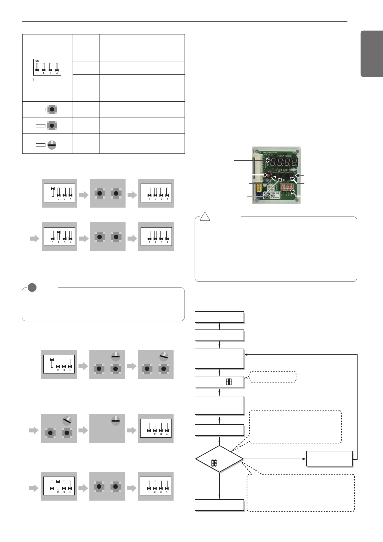
DIP-SWITCH
SW01D(reset)
SW04C(x:cancel)
7-Segment
SW03C(▶:forward)
SW02C(◀:backward)
SW01C(●:confirm)
CAUTION
• In replacement of the indoor unit PCB, always perform Automatic
addressing setting again (At that time, please check about using
Independent power module to any indoor unit.)
• If power supply is not applied to the indoor unit, operation error
occur.
• Automatic Addressing is only possible on the master Unit.
• Automatic Addressing has to be performed after 3 minutes to im-
prove communication.
!
The Procedure of Automatic Addressing
• Automatic addressing setting end
Numbers of indoor unit connection set whose
addressing is completed are indicated for 30seconds
on 7-segment LED after completing setting
Indoor address number is displayed on wired remote control or
indoor unit display window. It is not an error message, will
disappeared when on/off button is pressed on remote control
ex) Display of 01, 02, ..., 15 means connection of 15 indoor units
and Automatic addressing is completed normally.
Automatic addressing start
Waiting 3 minutes
Power On
Press RED Button
for 5 seconds.
(SW01C)
7-segment LED = 88
Don’t press RED Button
(SW01C)
Waiting about 2~7 minutes
7-segment LED
OK
YES
NO Check the connections
of communication cable
= 88
Automatic Addressing
The address of indoor units would be set by Automatic Addressing
- Wait for 3 minutes after supplying power.
(Master and Slave outdoor units, indoor units)
- Press RED button of the outdoor units for 5 seconds. (SW01C)
- A “88” is indicated on 7-segment LED of the outdoor unit PCB.
- For completing addressing, 2~7 minutes are required depending on
numbers of connected indoor units
-
Numbers of connected indoor units whose addressing is completed are
indicated for 30 seconds on 7-segment LED of the outdoor unit PCB
- After completing addressing, address of each indoor unit is indicated
on the wired remote control display window. (CH01, CH02,
CH03, ……, CH06 : Indicated as numbers of connected indoor units)
[Heat Recovery (SERVICE PCB)]
S/W No. Setup
No.1
Manual addressing of valve #1 (Master)
/ #5 (Slave)
No.2
Manual addressing of valve #2 (Master)
/ #6 (Slave)
No.3
Manual addressing of valve #3 (Master)
/ #7 (Slave)
No.4
Manual addressing of valve #4 (Master)
/ #8 (Slave)
SW02B
SW02B
Increase in the digit of 10 of valve ad-
dress
SW01B
SW01B
Increase in the last digit of valve ad-
dress
SW01C
0
SW01C
Manual addressing of zoning indoor
units
* Use for Zoning setting
SW01E
SW01E
SW #1 On : Select Valve #1
Master
ON
OFF
SW02B SW01B
Input the central control
address of Indoor unit
Master
SW01E
SW #1 Off : Finish Valve #1
Master
ON
OFF
SW01E
SW #2 On : Select Valve #6
Slave
ON
OFF
SW02B SW01B
Input the central control
address of Indoor unit
Slave
SW01E
SW #2 Off : Finish Valve #6
Slave
ON
OFF
1) Normal setting (Non-Zoning setting)
ex) Manual pipe detection of Valve #1, 6.
SW01E
SW #1 On : Select Valve #5
Slave
ON
OFF
SW02B SW01B
SW01C
After selecting No.1 zoning
indoor unit, input the central
control address of indoor unit.
Slave
After selecting No.2 zoning
indoor unit, input the central
control address of indoor unit.
Setting SW01C to ‘0’After selecting No.3 zoning
indoor unit, input the central
control address of indoor unit.
SW01E
SW #1 Off : Finish Valve #5
Slave
ON
OFF
SW01E
SW #2 On : Select Valve #6
Slave
ON
OFF
SW02B SW01B
Input the central control
address of Indoor unit
Slave
SW01E
SW #2 Off : Finish Valve #6
Slave
ON
OFF
0
SW02B
SW01C
SW01B
Slave
1
SW01C
Slave
0
SW02B
SW01C
SW01B
Slave
2
NOTE
!
Use the Zoning Control when install two or more indoor units at 1 branch of HR
Unit.
The indoor units controlled by Zoning Control can be selected collectively as the
cooling/heating mode.
2) Zoning setting
ex) Manual pipe detection of Valve #5 with three zoning indoor units,
#6 without zoning unit.
1,MFL69717904,영영 18. 8. 29. 영영 2:50 Page 27
Loading ...
Loading ...
Loading ...