
MFL69717904
Rev.01_073018
INSTALLATION MANUAL
AIR
CONDITIONER
www.lg.com
Please read this installation manual completely before installing the product.
Installation work must be performed in accordance with the national wiring
standards by authorized personnel only.
Please retain this installation manual for future reference after reading it
thoroughly.
Original instruction
Copyright © 2018 LG Electronics Inc. All Rights Reserved.
ENGLISH
ITALIANO
ESPAÑOL
FRANÇAIS DEUTSCH
ČEŠTINA
ΕΛΛΗΝΙΚΆ
NEDERLANDS
POLSKI
LIMBA ROMÂNĂ
РУССКИЙ ЯЗЫК
УКРАÏНСЬКА
1,MFL69717904,영영 18. 8. 29. 영영 2:49 Page 1
2
ENGLISH
• Do not cool excessively indoors. This may be harmful for your health
and may consume more electricity.
• Block sunlight with blinds or curtains while you are operating the air
conditioner.
• Keep doors or windows closed tightly while you are operating the air
conditioner.
• Adjust the direction of the air flow vertically or horizontally to circulate
indoor air.
• Speed up the fan to cool or warm indoor air quickly, in a short period
of time.
• Open windows regularly for ventilation as the indoor air quality may
deteriorate if the air conditioner is used for many hours.
• Clean the air filter once every 2 weeks. Dust and impurities collected
in the air filter may block the air flow or weaken the cooling / dehu-
midifying functions.
For your records
Staple your receipt to this page in case you need it to prove the date of
purchase or for warranty purposes. Write the model number and the
serial number here:
Model number :
Serial number :
You can find them on a label on the side of each unit.
Dealer’s name :
Date of purchase :
TIPS FOR SAVING ENERGY
Here are some tips that will help you minimize the power consumption
when you use the air conditioner. You can use your air conditioner
more efficiently by referring to the instructions below:
IMPORTANT SAFETY INSTRUC-
TIONS
READ ALL INSTRUCTIONS BEFORE
USING THE APPLIANCE.
Always comply with the following precautions
to avoid dangerous situations and ensure peak
performance of your product
WARNING
It can result in serious injury or death when the
directions are ignored.
CAUTION
It can result in minor injury or product damage
when the directions are ignored.
WARNING
• Installation or repairs made by unqualified
persons can result in hazards to you and oth-
ers.
• The information contained in the manual is
intended for use by a qualified service tech-
nician familiar with safety procedures and
equipped with the proper tools and test in-
struments.
• Failure to carefully read and follow all in-
structions in this manual can result in equip-
ment malfunction, property damage,
personal injury and/or death.
Installation
• Have all electric work done by a licensed
electrician according to "Electric Facility En-
gineering Standard" and "Interior Wire Regu-
lations" and the instructions given in this
manual and always use a special circuit.
- If the power source capacity is inadequate
or electric work is performed improperly,
electric shock or fire may result.
• Ask the dealer or an authorized technician to
install the air conditioner.
- Improper installation by the user may result
in water leakage, electric shock, or fire.
• Always ground the product.
- There is risk of fire or electric shock.
• Always intstall a dedicated circuit and
breaker.
- Improper wiring or installation may cause
fire or electric shock.
• For re-installation of the installed product, al-
ways contact a dealer or an Authorized Serv-
ice Center.
- There is risk of fire, electric shock, explo-
sion, or injury.
• Do not install, remove, or re-install the unit
by yourself (customer).
- There is risk of fire, electric shock, explo-
sion, or injury.
• Do not store or use flammable gas or com-
bustibles near the air conditioner.
- There is risk of fire or failure of product.
• Use the correctly rated breaker or fuse.
- There is risk of fire or electric shock.
• Prepare for strong wind or earthquake and
install the unit at the specified place.
- Improper installation may cause the unit to
topple and result in injury.
• Do not install the product on a defective in-
stallation stand.
- It may cause injury, accident, or damage to
the product.
!
!
!
1,MFL69717904,영영 18. 8. 29. 영영 2:49 Page 2

3
• Use a vacuum pump or Inert(nitrogen) gas
when doing leakage test or air purge. Do not
compress air or Oxygen and do not use
Flammable gases. Otherwise, it may cause
fire or explosion.
- There is the risk of death, injury, fire or ex-
plosion.
• When installing and moving the air condi-
tioner to another site, do not charge it with a
different refrigerant from the refrigerant
specified on the unit.
- If a different refrigerant or air is mixed with
the original refrigerant, the refrigerant cycle
may malfunction and the unit may be dam-
aged.
• Do not reconstruct to change the settings of
the protection devices.
- If the pressure switch, thermal switch, or
other protection device is shorted and op-
erated forcibly, or parts other than those
specified by LGE are used, fire or explosion
may result.
• Ventilate before operating air conditioner
when gas leaked out.
- It may cause explosion, fire, and burn.
• Securely install the cover of control box and
the panel.
- If the cover and panel are not installed se-
curely, dust or water may enter the out-
door unit and fire or electric shock may
result.
• If the air conditioner is installed in a small
room, measures must be taken to prevent
the refrigerant concentration from exceed-
ing the safety limit when the refrigerant
leaks.
- Consult the dealer regarding the appropri-
ate measures to prevent the safety limit
from being exceeded. Should the refriger-
ant leak and cause the safety limit to be ex-
ceeded, harzards due to lack of oxygen in
the room could result.
Operation
• Do not damage or use an unspecified power
cord.
- There is risk of fire, electric shock, explosion, or
injury.
• Use a dedicated outlet for this appliance.
- There is risk of fire or electrical shock.
• Be cautious that water could not enter the prod-
uct.
- There is risk of fire, electric shock, or product
damage.
• Do not touch the power switch with wet hands.
- There is risk of fire, electric shock, explosion, or
injury.
• When the product is soaked (flooded or sub-
merged), contact an Authorized Service Center.
- There is risk of fire or electric shock.
• Be cautious not to touch the sharp edges when
installing.
- It may cause injury.
• Take care to ensure that nobody could step on or
fall onto the outdoor unit.
- This could result in personal injury and product
damage.
• Do not open the inlet grille of the product during
operation. (Do not touch the electrostatic filter, if
the unit is so equipped.)
- There is risk of physical injury, electric shock, or
product failure.
CAUTION
Installation
• Always check for gas (refrigerant) leakage after in-
stallation or repair of product.
- Low refrigerant levels may cause failure of product.
• Do not install the product where the noise or hot air
from the outdoor unit could damage the neighbor-
hoods.
- It may cause a problem for your neighbors.
• Keep level even when installing the product.
- To avoid vibration or water leakage.
• Do not install the unit where combustible gas may
leak.
- If the gas leaks and accumulates around the unit,
an explosion may result.
• Use power cables of sufficient current carrying ca-
pacity and rating.
- Cables that are too small may leak, generate heat,
and cause a fire.
• Do not use the product for special purposes, such as
preserving foods, works of art, etc. It is a consumer
air conditioner, not a precision refrigeration system.
- There is risk of damage or loss of property.
• Keep the unit away from children. The heat ex-
changer is very sharp.
- It can cause the injury, such as cutting the finger.
Also the damaged fin may result in degradation of
capacity.
• When installting the unit in a hospital, communica-
tion station, or similar place, provide sufficient pro-
!
ENGLISH
1,MFL69717904,영영 18. 8. 29. 영영 2:49 Page 3

4
ENGLISH
tection against noise.
-
The inverter equipment, private power genera-
tor, high-frequency medical equipment, or radio
communication equipment may cause the air
conditioner to operate erroneously, or fail to op-
erate. On the other hand, the air conditioner may
affect such equipment by creating noise that dis-
turbs medical treatment or image broadcasting.
• Do not install the product where it is exposed to sea
wind (salt spray) directly.
- It may cause corrosion on the product. Corrosion,
particularly on the condenser and evaporator fins,
could cause product malfunction or inefficient oper-
ation.
Operation
• Do not use the air conditioner in special environ-
ments.
-
Oil, steam, sulfuric smoke, etc. can significantly re-
duce the performance of the air conditioner or damage
its parts.
• Do not block the inlet or outlet.
- It may cause failure of appliance or accident.
• Make the connections securely so that the outside
force of the cable may not be applied to the termi-
nals.
- Inadequate connection and fastening may generate
heat and cause a fire.
• Be sure the installation area does not deteriorate
with age.
- If the base collapses, the air conditioner could fall
with it, causing property damage, product failure, or
personal injury.
•
Install and insulate the drain hose to ensure that water
is drained away properly based on the installation man-
ual.
- A bad connection may cause water leakage.
• Be very careful about product transportation.
- Only one person should not carry the product if it
weighs more than 20kg(44lbs).
-
Some products use PP bands for packaging. Do not
use any PP bands for a means
of transportation. It is dangerous.
- Do not touch the heat exchanger fins. Doing so
may cut your fingers.
- When transporting the outdoor unit, suspending it
at the specified positions on the unit base. Also
support the outdoor unit at four points so that it
cannot slip sideways.
• Safely dispose of the packing materials.
-
Packing materials, such as nails and other metal or
wooden parts, may cause stabs or other injuries.
-
Tear apart and throw away plastic packaging bags so
that children may not play with them. If children play
with a plastic bag which was not torn apart, they face
the risk of suffocation.
• Turn on the power at least 6 hours before starting
operation.
- Starting operation immediately after turning on the
main power switch can result in severe damage to
internal parts. Keep the power switch turned on
during the operational season.
• Do not touch any of the refrigerant piping during and
after operation.
- It can cause a burn or frostbite.
• Do not operate the air conditioner with the panels or
guards removed.
- Rotating, hot, or high-voltage parts can cause in-
juries.
• Do not directly turn off the main power switch after
stopping operation.
- Wait at least 5 minutes before turning off the main
power switch. Otherwise it may result in water
leakage or other problems.
•
Auto-addressing should be done in condition of con-
necting the power of all indoor and outdoour units.
Auto-addressing should also be done in case of chang-
ing the indoor unit PCB.
• Use a firm stool or ladder when cleaning or maintain-
ing the air conditioner.
- Be careful and avoid personal injury.
• Do not insert hands or other objects through the air
inlet or outlet while the air conditioner is plugged in.
- There are sharp and moving parts that could cause
personal injury.
1,MFL69717904,영영 18. 8. 29. 영영 2:49 Page 4

5
ENGLISH
2 TIPS FOR SAVING ENERGY
2 IMPORTANT SAFETY INSTRUCTIONS
6 INSTALLATION PROCESS
6 OUTDOOR UNITS INFORMATION
6 ALTERNATIVE REFRIGERANT R410A
7 SELECT THE BEST LOCATION
8 INSTALLATION SPACE
9 Air guide work
10 LIFTING METHOD
10 INSTALLATION
10 The location of the Anchor bolts
10 Foundation for Installation
11 Preparation of Piping
12 Plumbing materials and storage methods
13 REFRIGERANT PIPING INSTALLATION
13 Precautions on Pipe connection / Valve operation
13 Installation procedure for HR unit
13 Installation of Outdoor Unit, HR Unit and Indoor Unit Refrigerant Pipe
14 Type of HR Unit
14 Installation of Zoning Control
15 PIPE CONNECTIONS BETWEEN INDOOR AND OUTDOOR UNIT
15 Preparation Work
15 Pipe Drawing Out during Single / Series connection
16 Refrigerant piping system
18 Refrigerant charging
19 Branch pipe Fitting
20 Leak Test and Vacuum drying
21 Vacuum Mode
21 Thermal insulation of refrigerant piping
22 ELECTRICAL WIRING
22 Caution
23 Control box and connecting position of wiring
23 Communication and Power Cables
24 Wiring of main power supply and equipment capacity
24 Field Wiring
25 Checking the setting of outdoor units
25 HR UNIT PCB
25 Setup the switch of HR Unit
27 Automatic Addressing
28 Example of manual valve addressing (Non-Zoning setting)
28 Example of manual valve addressing (Zoning setting)
29 Method of checking the pipe detection result at HR unit
29 Identification of Manual Valve ID (Address)
30 Group Number setting
30 TEST RUN
30 Cool & Heat selector
31 Static pressure compensation mode
31 Night Low Noise Function
31 Setting the ODU address
31 Snow removal & rapid defrost
32 Target pressure adjusting
33 Self-Diagnosis Function
35 CAUTION FOR REFRIGERANT LEAK
35 Introduction
35 Checking procedure of limiting concentration
36 INSTALLATION GUIDE AT THE SEASIDE
36 Model Designation
36 Airborne Noise Emission
TABLE OF CONTENTS
1,MFL69717904,영영 18. 8. 29. 영영 2:49 Page 5
6
ENGLISH
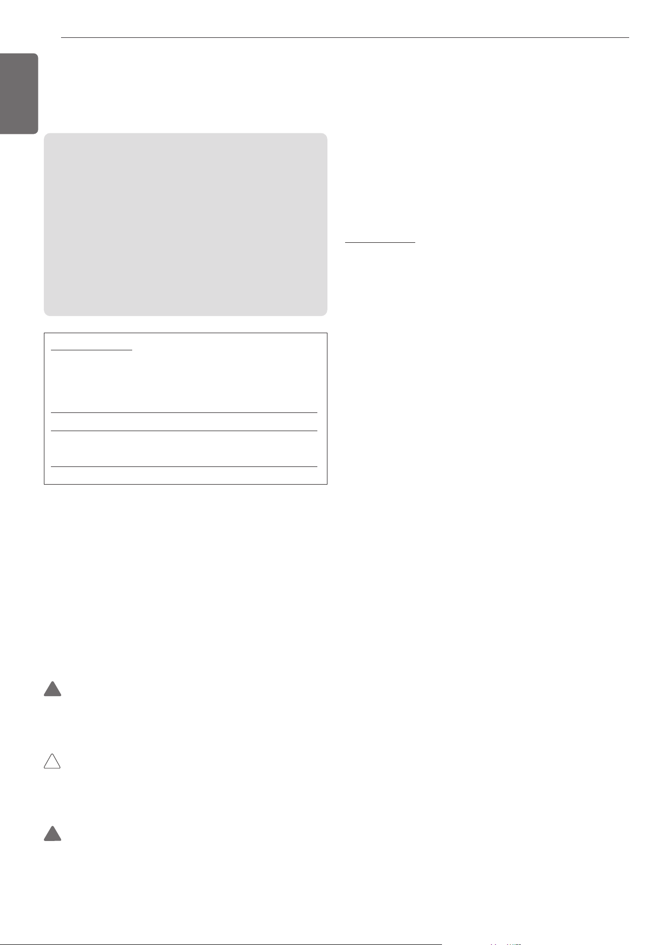
The foundation must be level even
Outdoor unit foundation work
Avoid short circuits and ensure
sufficient space is allowed for service
Installation of outdoor unit
Refer to automatic addressing flowchart
Automatic addressing and
pipe dection of indoor unit
In the final check for 24hours at 3.8 MPa(38.7 kgf/cm
2
) there
must be no drop in pressure.
Airtight test
Multiple core cable must not be used.
(suitable cable should be selected)
Electrical work
(connection circuits and drive circuits)
Make sure no gaps are left where
the insulating materials are joined
Heat insulation work
Make sure airflow is sufficient
Duct work
Adjust to downward gradient
Drain pipe work
Special attention to dryness,
cleanness and tightness
Refrigerant piping work
Check model name to
make sure the fitting
is made correctly
Installation of indoor unit
Take account of gradient
of drain piping
Sleeve and insert work
Make connection clearly between outdoor, indoor,
remote controller and option.
Preparation of contract drawings
Indicate clearly who will be responsible for switch setting.
Determination of division work
The vacuum pump used must have a capacity of reaching at least
5 torr, more than 1 hour
Vacuum drying
Recharge correctly as calculated in this manual. and record the
amount of added refrigerant
Additional charge of refrigerant
Make sure there are no gaps left between the facing materials
used on the ceiling
Fit facing panels
Run each indoor unit in turn to make sure the pipe work
has been fitted correctly
Test run adjustment
Explain the use of the system as clearly as possible to your customer and
make sure all relevant documentation is in order
Transfer to customer with explanation
Preheat the compress for more than 6 hours.
CAUTION
• The above list indicates the order in which the individual work opera-
tions are normally carried out but this order may be varied where
local conditions warrants such change.
• The thickness of the piping should comply with the relevant local
and national regulations for the designed pressure 3.8MPa(551.1psi).
• Since R410A is a mixed refrigerant, the required additional
refrigerant must be charged in its liquid state.(If the refrigerant is
charged in its gaseous state, its composition changes and the sys-
tem will not work properly.)
!
CAUTION
• Ratio of the connectable Indoor Units to the Outdoor: 50 ~ 160%
• Ratio of running Indoor Units to the Outdoor: 10 ~ 100%
• A combination operation over 100% cause to reduce each indoor
unit capacity.
!
CAUTION
• The wall thickness of the piping should comply with the relevant
local and national regulations for the designed pressure
3.8MPa(551.1psi).
• Since R410A is a mixed refrigerant, the required additional
refrigerant must be charged in its liquid state.
If the refrigerant is charged in its gaseous state, its composition
changes and the system will not work properly.
• Do not place the refrigerant container under the direct rays of the
sun to prevent it from exploding.
• For high-pressure refrigerant, any unapproved pipe must not be
used.
• Do not heat pipes more than necessary to prevent them from
softening.
• Be careful not to install wrongly to minimize economic loss
because it is expensive in comparison with R22.
!
ALTERNATIVE REFRIGERANT R410A
The refrigerant R410A has the property of higher operating pressure in
comparison with R22.
Therefore, all materials have the characteristics of higher resisting
pressure than R22 ones and this characteristic should be also consid-
ered during the installation.
R410A is an azeotrope of R32 and R125 mixed at 50:50, so the ozone
depletion potential (ODP) of R410A is 0.
OUTDOOR UNITS INFORMATIONINSTALLATION PROCESS
1,MFL69717904,영영 18. 8. 29. 영영 2:49 Page 6
7
ENGLISH
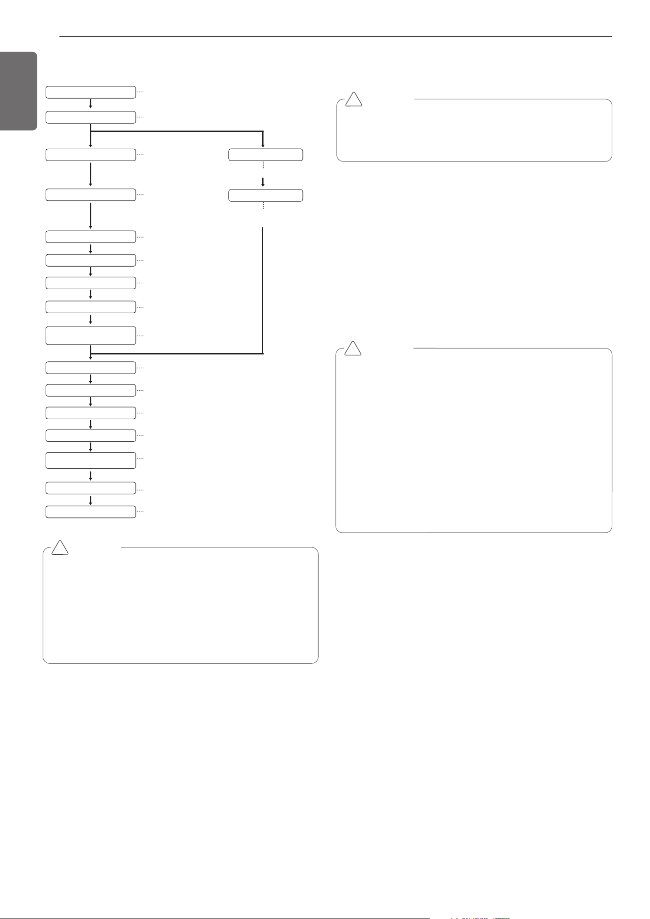
Air inlet grille
500mm
(19-11/16inch)
[Unit:mm(inch)]
Turn the air outlet side toward the
building's wall, fence or windbreak screen.
For detailed instructions on installing the HR Unit, see the installation
manual included with the HR Unit.
WARNING
Fix the outdoor unit firmly with anchor bolt or it may fall and hurt
people. (refer to ‘Foundation for installation’)
!
SELECT THE BEST LOCATION
Select space for installing outdoor unit, which will meet the following
conditions:
• No direct thermal radiation from other heat sources
• No possibility of annoying neighbors by noise from unit
• No exposition to strong wind
• With strength which bears weight of unit
• Note that drain flows out of unit when heating
• With space for air passage and service work shown next
• Because of the possibility of fire, do not install unit to the space
where generation, inflow, stagnation, and leakage of combustible
gas is expected.
• Avoid unit installation in a place where acidic solution and spray (sul-
fur) are often used.
• Do not use unit under any special environment where oil, steam and
sulfuric gas exist.
• It is recommended to fence round the outdoor unit in order to pre-
vent any person or animal from accessing the outdoor unit.
• If installation site is area of heavy snowfall, then the following direc-
tions should be observed.
- Make the foundation as high as possible.
- Fit a snow protection hood.
Select installation location considering following conditions to avoid
bad condition when additionally performing defrost operation.
• Install the outdoor unit at a place well ventilated and having a lot of
sunshine in case of installing the product at a place with a high hu-
midity in winter (near beach, coast, lake, etc).
(Ex) Rooftop where sunshine always shines.
• Performance of heating will be reduced and preheat time of the in-
door unit may be lengthened in case of installing the outdoor unit in
winter at following location:
- Shade position with a narrow space
- Location with much moisture in neighboring floor.
- Location with much humidity around.
- Location where ventilation is good. It is recommended to install the
outdoor unit at a place with a lot of sunshine as possible as.
- Location where water gathers since the floor is not even.
When installing the outdoor unit in a place that is constantly exposed to a
strong wind like a coast or on a high story of a building, secure a normal
fan operation by using a duct or a wind shield.
• Install the unit so that its discharge port faces to the wall of the build-
ing.
Keep a distance 500mm(19-11/16inch) or more between the unit and
the wall surface.
• Supposing the wind direction during the operation season of the air
conditioner, install the unit so that the discharge port is set at right
angle to the wind direction.
- Avoid a place where oil spattering, vapor spray or high frequency
electric noise is expected.
- Install the unit at a place in which it is not affected by operation noise.
(Installation within cell such as meeting room etc. may disturb busi-
ness due to noise.)
• Place where refrigerant piping, drain piping and electrical wiring
works are easy.
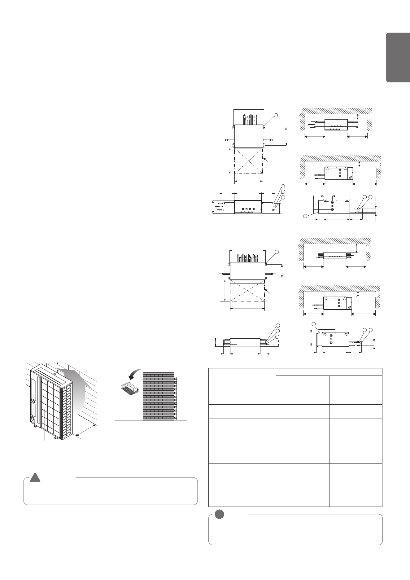
Select installation location of the HR unit suitable for following condi-
tions
- Avoid a place where rain may enter since the HR unit is for indoor.
- Sufficient service space must be obtained.
- Refrigerant pipe must not exceed limited length.
- Avoid a place subject to a strong radiation heat from other heat
source.
NOTE
!
• Be sure to install the inspection door at the control box side.
• If reducers are used, servicing space must be increased equal to reducer's di-
mension.
300 more
300 more
300 more
450
more
(Servicing space) (Servicing space)
(Servicing space)
(Servicing space)
100 more
(Serviceing space)
500
7
311
1
2
3
100 more
(Serviceing space)
126
147
6
54
19
55
38992 176
Inspection door
(servicing space)
500
540
150 486 150
165
218
[Unit : mm]
PRHR023/PRHR033/PRHR043
300 more
300 more
300 more
450
more
(Servicing space) (Servicing space)
(Servicing space)
(Servicing space)
100 more
(Serviceing space)
7
311
809
793
160
160
218
165
1
2
3
100 more
(Serviceing space)
19
55
389
92
176
147
126
5
4
6
540
Inspection door
(servicing space)
800
[Unit : mm]
PRHR063/PRHR083
No. Part Name
Description
PRHR033/PRHR043
PRHR063/PRHR083
PRHR023
1
Low pressure Gas pipe
connection port
Ø28.58 Brazing con-
nection
Ø22.2 Brazing connec-
tion
2
High pressure Gas pipe
connection port
Ø22.2 Brazing connec-
tion
Ø19.05 Brazing con-
nection
3
Liquid pipe connection
port
Ø15.88 Brazing con-
nection
(In case of PRHR033,
use Ø12.7)
Ø9.52 Brazing connec-
tion
4
Indoor unit Gas pipe
connection port
Ø15.88– Ø12.7
Brazing connection
Ø15.88– Ø12.7
Brazing connection
5
Indoor unit Liquid pipe
connection port
Ø9.52 – Ø6.35
Brazing connection
Ø9.52 – Ø6.35
Brazing connection
6 Control box - -
7 Hanger metal
Suspension bolt M10
or M8
Suspension bolt M10
or M8
[Unit : mm]
1,MFL69717904,영영 18. 8. 29. 영영 2:49 Page 7
8
ENGLISH
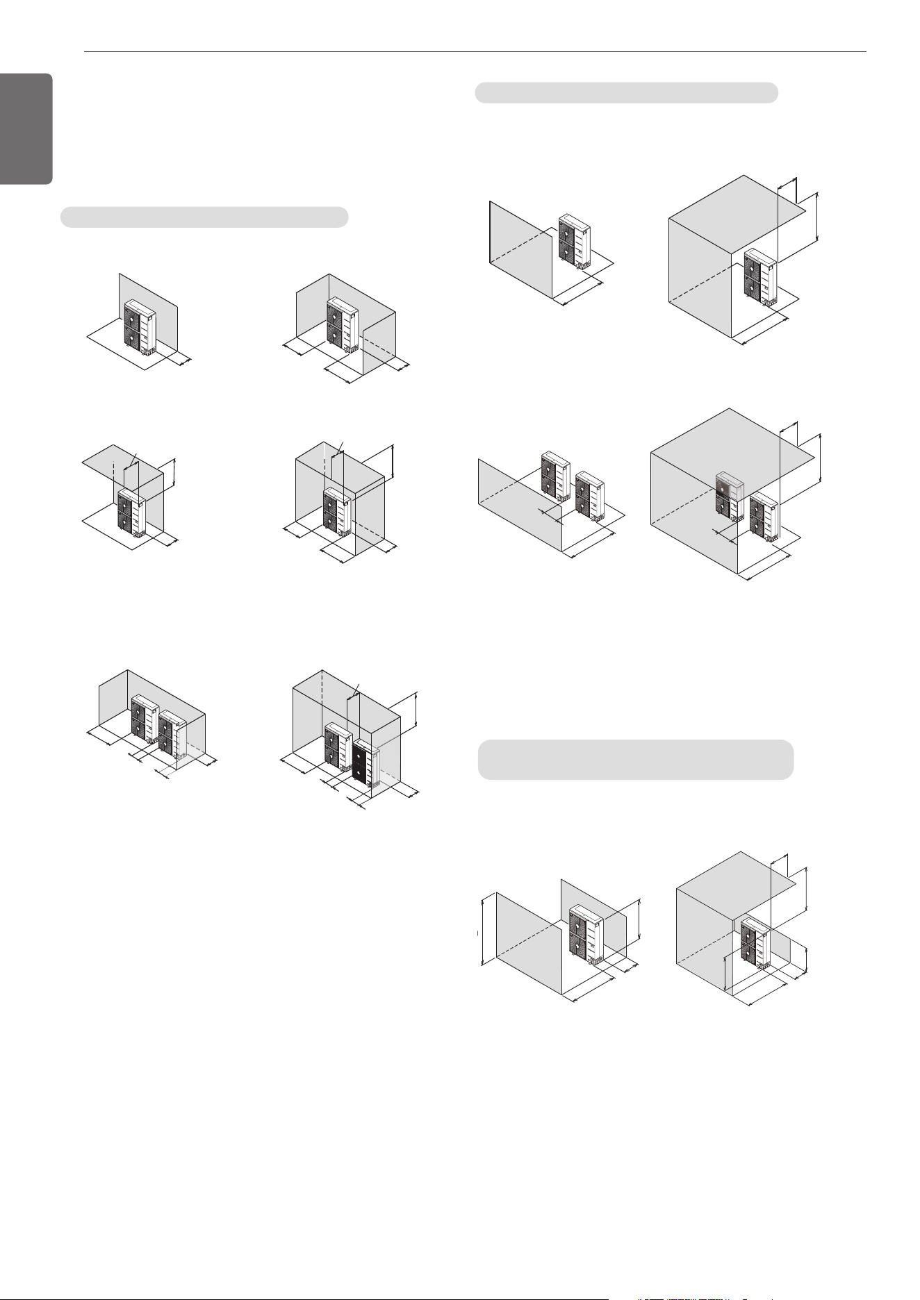
• The following values are the least space for installation. If any service
area is needed for service according to field circumstance, obtain
enough service space.
• The unit of values is mm.
In case of obstacles on the suction side
1. Stand alone installation
100(3-15/16)
or more
1000 (39-1/4)
or more
100(3-15/16)
or more
500(19-5/8)
or less
100(3-15/16)
or more
100(3-15/16)
or more
100(3-15/16)
or more
500(19-5/8)
or less
1000 (39-1/4)
or more
150(5-29/32)
or more
100(3-15/16)
or more
150(5-29/32)
or more
2. Collective installation
100(3-15/16)
or more
100(3-15/16)
or more
1000 (39-1/4)
or more
300(11-13/16)
or more
500(19-5/8)
or less
1000 (39-1/4)
or more
100(3-15/16)
or more
100(3-15/16)
or more
1000 (39-1/4)
or more
300(11-13/16)
or more
INSTALLATION SPACE
Unit:mm(inch)
Unit:mm(inch)
In case of obstacles on the discharge side
1. Stand alone installation
500(19-5/8) or more
500(19-5/8)
or less
1000 (39-1/4)
or more
500(19-5/8) or more
1000 (39-1/4)
or more
100(3-15/16)
or more
500(19-5/8) or less
1000 (39-1/4)
or more
1000 (39-1/4)
or more
100(3-15/16)
or more
H
L
100(3-15/16)
or more
500(19-5/8)
or more
1000 (39-1/4)
or more
500(19-5/8) or less
L
H
250 (9-7/8)
or more
1000 (39-1/4)
or more
2. Collective installation
In case of obstacles on the suction and the
discharge side
Obstacle height of discharge side is higher than the unit
1. Stand alone installation
Unit:mm(inch)
Unit:mm(inch)
L > H L > H
1,MFL69717904,영영 18. 8. 29. 영영 2:49 Page 8
9
ENGLISH
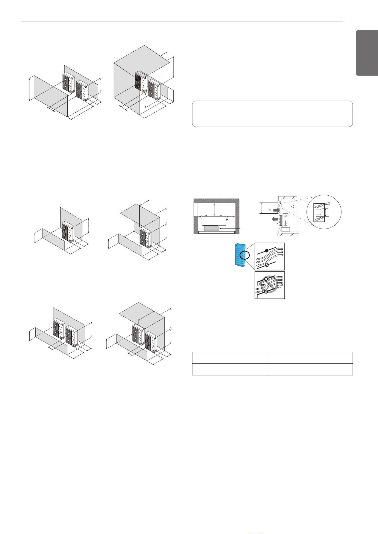
2. Collective installation
Unit:mm(inch)
Unit:mm(inch)
L
H
1000 (39-1/4)
or more
300(11-13/16)
or more
100(3-15/16)
or more
500(19-5/8)
or less
L
H
1250(49-1/4)
or more
300(11-13/16)
or more
1000 (39-1/4)
or more
100(3-15/16)
or more
H
L
100(3-15/16)
or more
500(19-5/8)
or less
500(19-5/8) or less
H
L
1000 (39-1/4)
or more
300(11-13/16)
o
r
more
1000 (39-1/4)
or more
H
L
300(11-13/16)
or more
100(3-15/16)
or more
1500(59)
or more
300(11-13/16)
or more
500(19-5/8)
or less
1000 (39-1/4)
or more
H
L
1500(59)
or more
100(3-15/16)
or more
L > H L > H
Obstacle height of discharge side is lower than the unit
1. Stand alone installation
2. Collective installation
L ≤ HL ≤ H
L ≤ HL ≤ H
Seasonal wind and cautions in winter
• Install correctly with the prospect of snow or cold temperatures in
mind.
• Install the outdoor unit ideally not to come into contact with snow di-
rectly. If snow piles up it will freeze to the heat exchanger, and the
system will malfunction. Attach a snow hood to prevent any issues.
• Install the outdoor unit 500mm higher than the average snowfall.
• Remove any snow that piles higher than 100mm on the top of the
unit.
- In areas of high wind, do not install the units heat exchanger or dis-
charge fan perpendicular to the wind direction.
Air guide work
In cases where the outdoor unit is installed in an enclosed space, care
should be taken to ensure adequate airflow around the product, other-
wise failure could occur.
• The operating ratio should be at least 80%
• Louver angle should be 0~20 degree
• Louver pitch should be more than 100mm(3.9inch)
Secure minimum intake area
When the intake area is not secured can efficiency drop and products
may not be operating
• Minimum intake area (For reference)
Model ARUB060GSS4
Minimum intake area 1.2(15.5)
300mm
(11-13/16inch)
or more
Air guide
Air guide duct
Less than
Less than
20 degrees
20 degrees
Wind speed : 1.5m/s(4.9 ft/s)
Intake
area
150mm
(5-29/32inch)
or more
350mm
350mm
(13-25/32inch)
(13-25/32inch)
or more
or more
350mm
(13-25/32inch)
or more
Less than
20 degrees
Louver pitch
Louver pitch
100 mm
100 mm
(3-15/16inch)
(3-15/16inch)
or more
or more
Louver pitch
100 mm
(3-15/16inch)
or more
Unit : m
2
(ft
2
)
1,MFL69717904,영영 18. 8. 29. 영영 2:49 Page 9
10
ENGLISH
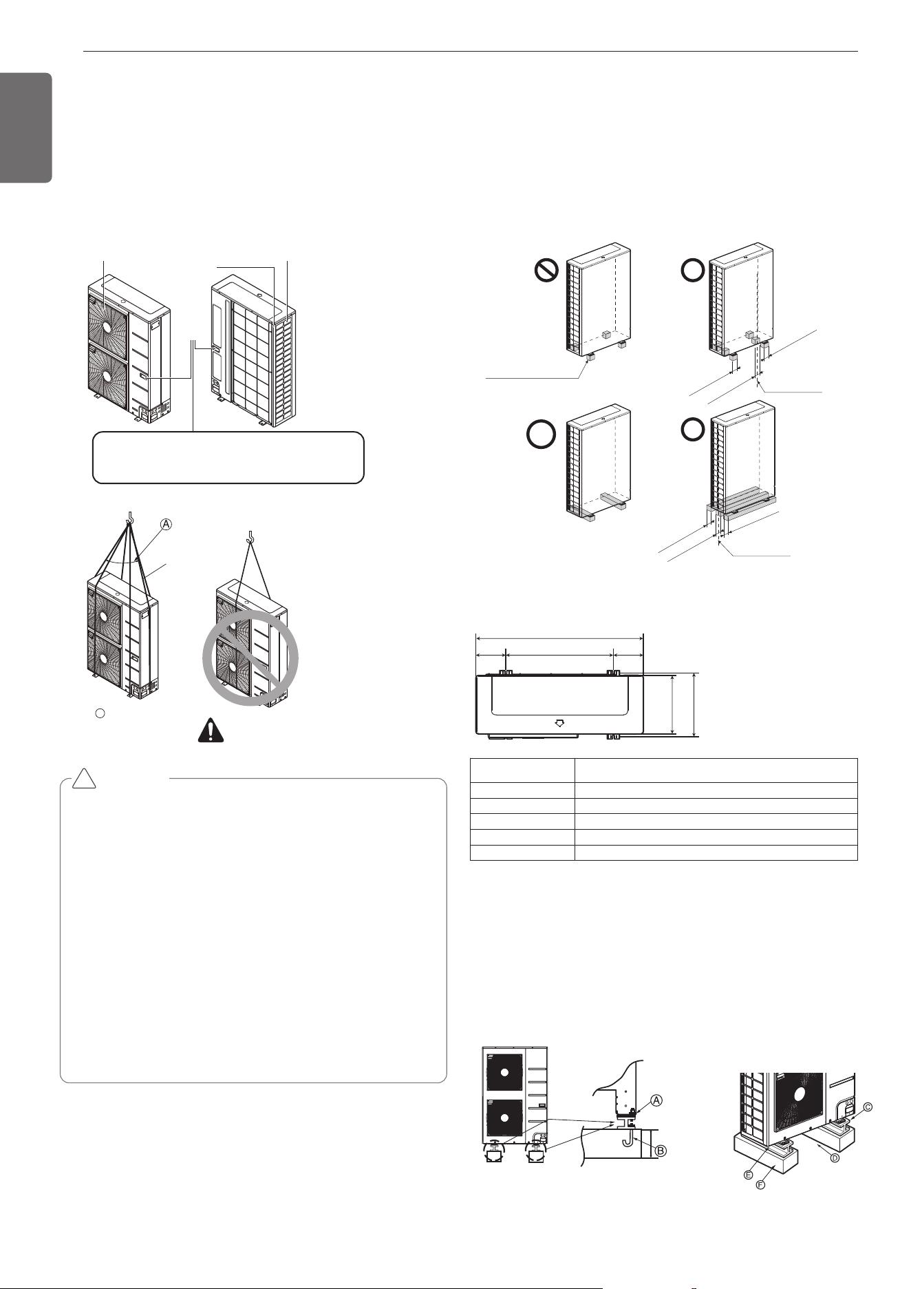
• When carrying the suspended, unit pass the ropes between legs of
base panel under the unit.
• Always lift the unit with ropes attached at four points so that impact
is not applied to the unit.
• Attach the ropes to the unit at an angle of 40° or less.
• Use only accessories and parts which are of the designated specifica-
tion when installing.
Air outlet grille Intake hole
Corner
Handle
Always hold the unit by the corners, as holding
it by the side intake holes on the casing may
cause them to deform.
Sub line
40° or less
A
WARNING
CAUTION
Be very careful while carrying the product.
•
Do not have only one person carry product if it is more than
20kg(44lbs).
• PP bands are used to pack some products. Do not use them as
a mean for transportation because they are dangerous.
• Do not touch heat exchanger fins with your bare hands. Other-
wise you may get a cut in your hands.
• Tear plastic packaging bag and scrap it so that children cannot
play with it. Otherwise plastic packaging bag may suffocate chil-
dren to death.
• When carrying in Outdoor Unit, be sure to support it at four
points. Carrying in and lifting with 3-point support may make
Outdoor Unit unstable, resulting in a fall.
• Use 2 belts of at least 8m(26.2 ft) long.
• Place extra cloth or boards in the locations where the casing
comes in contact with the sling to prevent damage.
•
Hoist the unit making sure it is being lifted at its center of gravity.
!
• Fix the unit tightly with bolts as shown below so that unit will not fall
down due to earthquake or gust.
• Use the H-beam support as a base support
• Noise and vibration may occur from the floor or wall since vibration is
transferred through the installation part depending on installation sta-
tus. Thus, use anti-vibration materials (cushion pad) fully (The base
pad shall be more than 200 mm(7-7/8 inch)).
At least 200mm
(7-7/8 inch)
Foundation for Installation
• Install at places where it can endure the weight and vibration/noise
of the outdoor unit.
• The outdoor unit supports at the bottom shall have width of at least
100mm(3-15/16inch) under the Unit’s legs before being fixed.
• The outdoor unit supports should have minimum height of 200mm(7-
7/8inch).
• Anchor bolts must be inserted at least 75mm(2-15/16inch).
At least 100mm
(3-15/16inch)
At least 100mm
(3-15/16inch)
At least 100mm
(
3-15/16inch)
At least 100mm
(3-15/16inch)
At least 100mm
(3-15/16inch)
At least 100mm
(3-15/16inch)
Center of the Unit
For outdoor units
should not be
supported only
by the corner
supports.
Center of the Unit
a
be
e
cd
ARUB060GSS4
a 920(36-7/32)
b 618(24-11/32)
c 330(13)
d 360(14-3/16)
e 151(5-15/16)
[Unit : mm(inch)]
The location of the Anchor bolts
INSTALLATIONLIFTING METHOD
1,MFL69717904,영영 18. 8. 29. 영영 2:49 Page 10
11
ENGLISH
Unit : mm(inch)
200 (7-7/8)
Nut
75 (3)
75 (3)
200 (7-7/8)
Spring washer
Frame
Anti-vibration
materials
Four bolt are
required
3 thread ridges
H-Beam
Concrete
base
100(3-15/16)
Ⓐ The corner part must be fixed firmly. Otherwise, the support for the
installation may be bent.
Ⓑ Get and use M10 Anchor bolt.
Ⓒ Put Cushion Pad between the outdoor unit and ground support for
the vibration protection in wide area.
Ⓓ Space for pipes and wiring (Pipes and wirings for bottom side)
Ⓔ H-beam support
Ⓕ Concrete support
CAUTION
• Be sure to remove the Pallet(Wood Support) of the bottom
side of the outdoor unit Base Pan before fixing the bolt. It
may cause the unstable state of the outdoor settlement,
and may cause freezing of the heat exchanger resulting in
abnormal operations.
• Be sure to remove the Pallet(Wood Support) of the bottom
side of the outdoor unit before welding. Not removing Pal-
let(Wood Support) causes hazard of fire during welding.
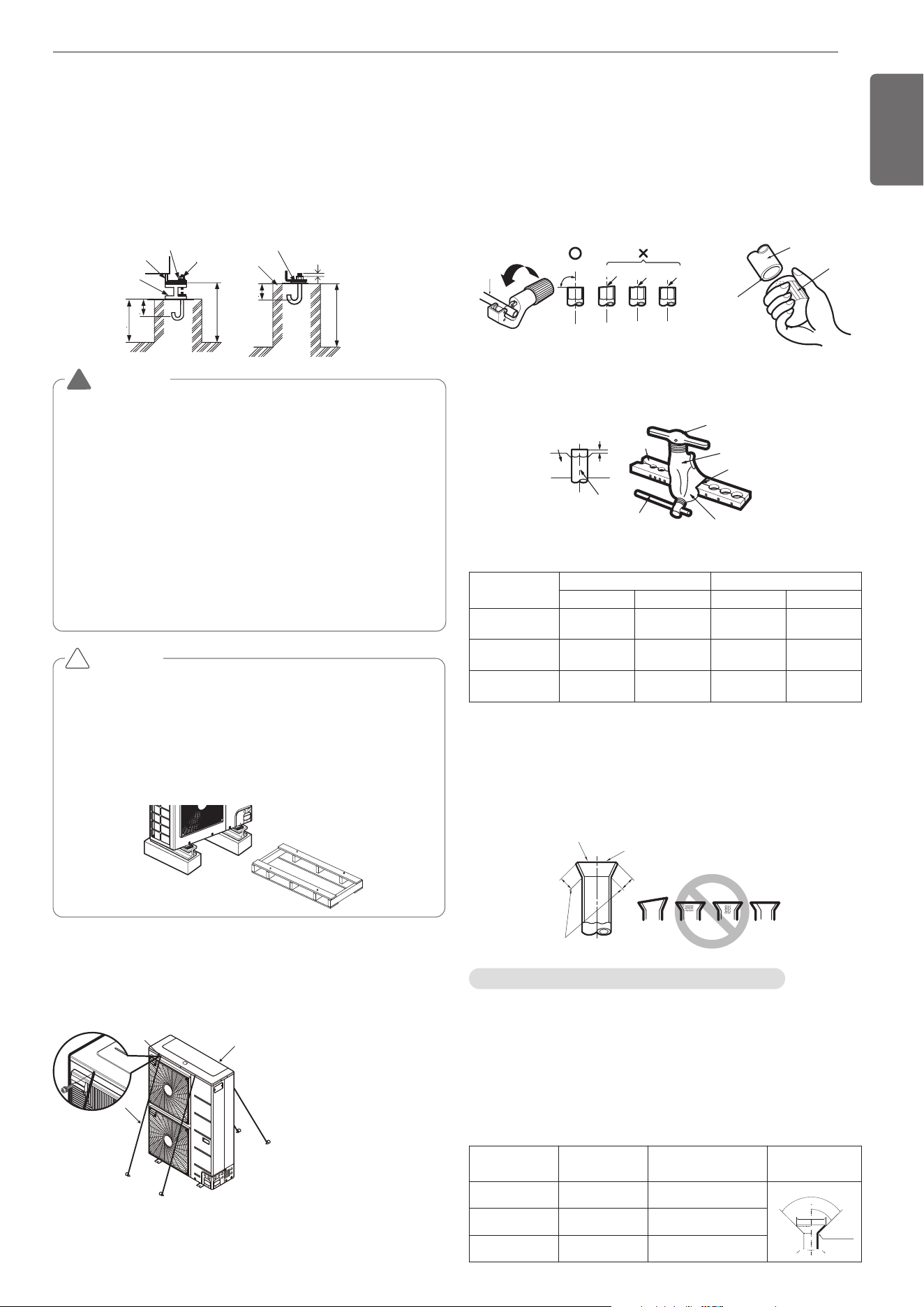
If it is necessary to prevent the unit from falling over, install as shown
in the figure.
• Prepare all 4 wires as indicated in the drawing
• Unscrew the top plate at the 4 location indicated A and B
• Put the screws through the nooses and screw them back tight
WARNING
• Install where it can sufficiently support the weight of the out-
door unit.
If the support strength is not enough, the outdoor unit may drop
and hurt people.
• Install where the outdoor unit may not fall in strong wind or
earthquake.
If there is a fault in the supporting conditions, the outdoor unit
may fall and hurt people.
• Please take extra cautions on the supporting strength of the
ground, water outlet treatment(treatment of the water flowing
out of the outdoor unit in operation), and the passages of the
pipe and wiring, when making the ground support.
• Do not use tube or pipe for water outlet in the Base pan. Use
drainage instead for water outlet. The tube or pipe may freeze
and the water may not be drained.
Pallet(Wood Support)
- Remove before Installation
!
!
A
B
C
A : Location of the 2 fixation
holes on the front side of
the unit
B : Location of the 2 fixation
holes on the rear side of
the unit
C : wires
Flaring work
- Carry out flaring work using flaring tool as shown below.
Firmly hold copper tube in a bar(or die) as indicated dimension in the
table above.
Check
- Compare the flared work with figure below.
- If flare is noted to be defective, cut off the flared section and do flar-
ing work again.
Burrs removal
- Completely remove all burrs from the cut cross section of pipe/tube.
- Put the end of the copper tube/pipe to downward direction as you re-
move burrs in order to avoid to let burrs drop in the tubing.
Bar
Copper pipe
Clamp handle
Red arrow mark
Cone
Yoke
Handle
Bar
"A"
Inclined
Inside is shining without scratches.
Smooth all round
Even length
all round
Surface
damaged
Cracked Uneven
thickness
= Improper flaring =
Flare shape and flare nut tightening torque
Precautions when connecting pipes
- See the following table for flare part machining dimensions.
- When connecting the flare nuts, apply refrigerant oil to the inside and
outside of the flares and turn them three or four times at first. (Use
ester oil or ether oil.)
-
See the following table for tightening torque.(Applying too much torque may
cause the flares to crack.)
- After all the piping has been connected, use nitrogen to perform a
gas leak check.
Pipe size
[mm(inch)]
Tightening
Torque[N
.
m(lbs
.
ft)]
A [mm(inch)] Flare shape
Ø9.52(3/8) 38±4(28±3.0) 12.8(0.5)~13.2(0.52)
90°
±2
4
5°
±
2
A
R=0.4~0.8
Ø12.7(1/2) 55±6(41±4.4) 16.2(0.64)~16.6(0.65)
Ø15.88(5/8) 75±7(55±5.2) 19.3(0.76)~19.7(0.78)
Main cause of gas leakage is defect in flaring work. Carry out correct
flaring work in the following procedure.
Cut the pipes and the cable
- Use the accessory piping kit or the pipes purchased locally.
- Measure the distance between the indoor and the outdoor unit.
- Cut the pipes a little longer than measured distance.
- Cut the cable 1500mm(59-1/16inch) longer than the pipe length.
Pipe
Reamer
Point down
Copper
tube
90°
Slanted Uneven Rough
Preparation of Piping
Indoor unit
[kW(Btu/h)]
Pipe [mm(inch)] "A" [mm(inch)]
Gas Liquid Gas Liquid
<5.6(19,100) 12.7(1/2) 6.35(1/4)
0.5~0.8
(0.02~0.03)
0~0.5
(0~0.02)
<16.0(54,600) 15.88(5/8) 9.52(3/8)
0.8~1.0
(0.03~0.04)
0.5~0.8
(0.02~0.03)
<22.4(76,400) 19.05(3/4) 9.52(3/8)
1.0~1.3
(0.04~0.05)
0.5~0.8
(0.02~0.03)
1,MFL69717904,영영 18. 8. 29. 영영 2:49 Page 11
12
ENGLISH
Opening shutoff valve
1 Remove the cap and turn the valve counter clockwise with the
hexagon wrench.
2 Turn it until the shaft stops.
Do not apply excessive force to the shutoff valve. Doing so may
break the valve body, as the valve is not a backseat type. Always
use the special tool.
3 Make sure to tighten the cap securely.
CAUTION
• Always use a charge hose for service port connection.
•
After tightening the cap, check that no refrigerant leaks are present
.
• When loosening a flare nut, always use two wrenches in
combination, When connecting the piping,
always use a spanner and torque wrench
in combination to tighten the flare nut.
• When connecting a flare nut, coat the
flare(inner and outer faces) with oil for
R410A(PVE) and hand tighten the nut
3 to 4 turns as the initial tightening.
Union
!
Insulation of shutoff valve
1 Use the heat insulation material for the refrigerant piping which has
an excellent heat-resistance (over 120°C).
2 Precautions in high humidity circumstance:
This air conditioner has been tested according to the "ISO Condi-
tions with Mist" and confirmed that there is not any default. How-
ever, if it is operated for a long time in high humid atmosphere
(dew point temperature: more than 23°C), water drops are liable to
fall. In this case, add heat insulation material according to the fol-
lowing procedure:
- Heat insulation material to be prepared... EPDM (Ethylene Propy-
lene Diene Methylene)-over 120°C the heat-resistance tempera-
ture.
- Add the insulation over 10mm thickness at high humidity environ-
ment.
Indoor unit
Thermal insulator
(accessory)
Fastening band
(accessory)
Refrigerant piping
Closing shutoff valve
1
Remove the cap and turn the valve clockwise with the hexagon wrench.
2 Securely tighten the valve until the shaft contacts the main body seal.
3 Make sure to tighten the cap securely.
* For the tightening torque, refer to the table on the below.
Tightening torque
Shut off
valve size
[mm(inch)]
Tightening torque N·m(lbs·ft) (Turn clockwise to close)
Shaft(valve body)
Cap
(Valve lid)
Service
port
Flare nut
Gas line pip-
ing attached
to unit
Closed Opened Hexagonal
Ø6.35(1/4)
6.0 ±0.6
(4.4±0.4)
5.0 ±0.5
(3.7±0.4)
4mm
(0.16inch)
17.6±2.0
(13.0±1.5)
12.7±2
(9.4±1.5)
16±2(12±1.5)
-
Ø9.52(3/8)
38±4(28±3.0)
Ø12.7(1/2)
10.0 ±1.0
(7.4±0.7)
20.0±2.0
(14.8±1.5)
55±6
(41±4.4)
Ø15.88(5/8)
12.0 ±1.2
(8.9±0.9)
5mm
(0.24inch)
25.0±2.5
(18.4±1.8)
75±7
(55±5.1)
Ø19.05(3/4)
14.0 ±1.4
(10.3±1.0)
110±10
(81.1±7.4)
Ø22.2(7/8)
30.0 ±3.0
(22.1±2.2)
8mm
(0.31inch)
-
25±3.0
(18.5±2.2)
Ø25.4(1.0)
Regulator
Auxiliary valve
Taping
(Should not
contain air)
Welding Point
Note) should not block the outlet side.
When the internal pressure in pipe is abo
ve the atmospheric pressure, pinhole is o
ccurred and it is a leakage cause.
Oxide scale
Nitrogen
Nitrogen gas Pressure
0.02MPa(2.9psi) less
Drying Cleanliness Airtight
Should be no moisture
inside
No dust inside.
There is no refrigerant
leakage
Items
Moisture
Dust
Leakage
Cause
failure
- Significant hydroly-
sis of refrigerant oil
- Degradation of re-
frigerant oil
- Poor insula’tion of
the compressor
- Do not cold and
warm
- Clogging of EEV,
Capillary
- Degradation of re-
frigerant oil
- Poor insulation of
the compressor
- Do not cold and
warm
- Clogging of EEV,
Capillary
- Gas shortages
- Degradation of re-
frigerant oil
- Poor insulation of
the compressor
- Do not cold and
warm
Coun-
termea-
sure
-
No moisture in the pipe
- Until the connec-
tion is completed,
the plumbing pipe
entrance should be
strictly controlled.
- Stop plumbing at
rainy day.
- Pipe entrance
should be taken
side or bottom.
-
When removal burr
after cutting pipe, pipe
entrance should be
taken down.
- Pipe entrance
should be fitted cap
when pass through
the walls.
- No dust in the pipe.
- Until the connec-
tion is completed,
the plumbing pipe
entrance should be
strictly controlled.
- Pipe entrance
should be taken
side or bottom.
- When removal burr
after cutting pipe,
pipe entrance
should be taken
down.
- Pipe entrance
should be fitted cap
when pass through
the walls.
- Airtightness test
should be.
- Brazing operations
to comply with
standards.
- Flare to comply
with standards.
- Flange connections
to comply with
standards.
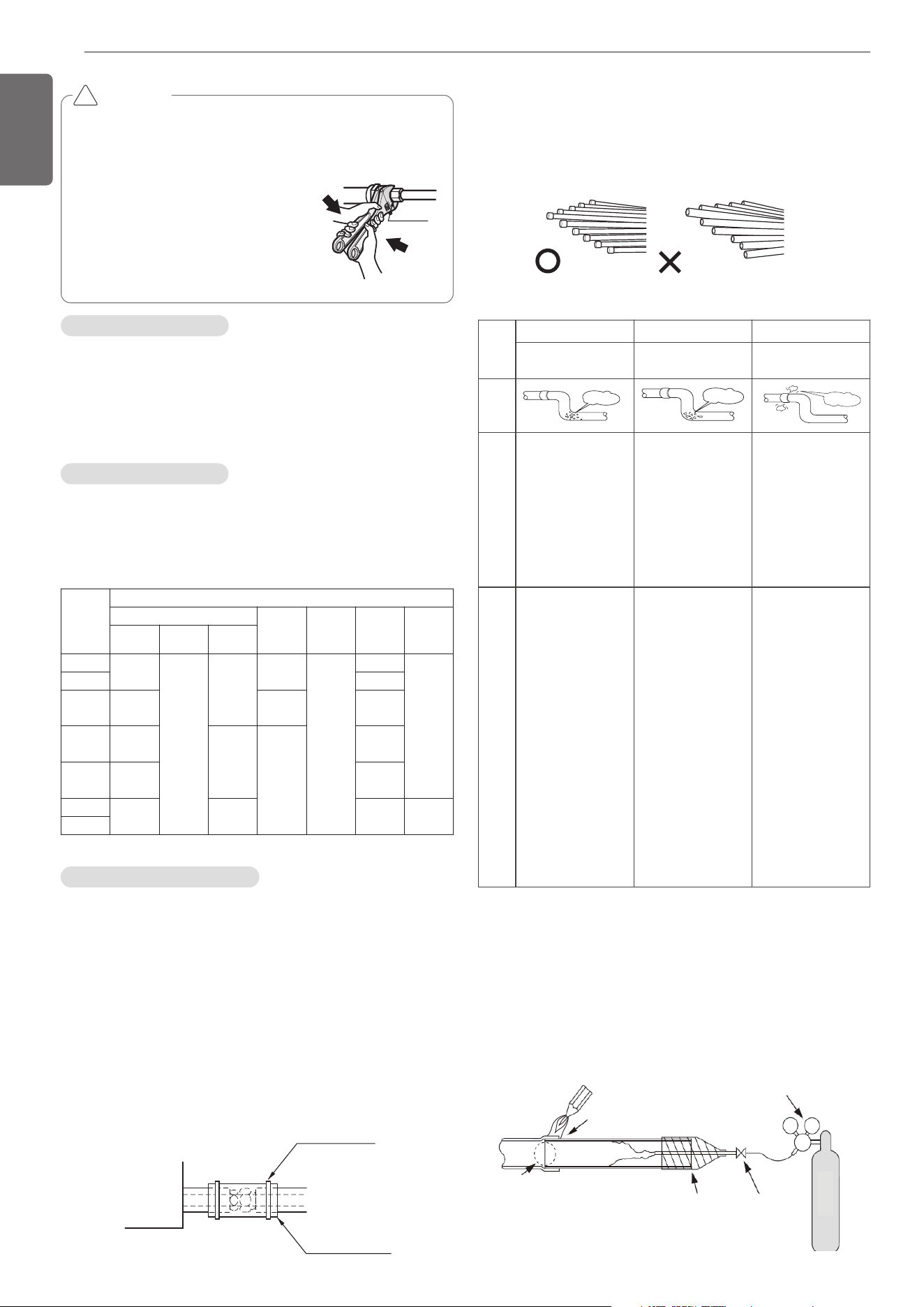
Nitrogen substitution method
Welding, as when heating without nitrogen substitution a large
amount of the oxide film is formed on the internal piping.
The oxide film is a caused by clogging EEV, Capillary, oil hole of accu-
mulator and suction hole of oil pump in compressor.
It prevents normal operation of the compressor.
In order to avoid this problem, Welding should be done after replacing
air by nitrogen gas.
When welding plumbing pipe, the work is required.
Refrigerant piping on three principles
Plumbing materials and storage methods
Pipe must be able to obtain the specified thickness and should be
used with low impurities.
Also when handling storage, pipe must be careful to prevent a frac-
ture, deformity and wound.
Should not be mixed with contaminations such as dust, moisture.
1,MFL69717904,영영 18. 8. 29. 영영 2:49 Page 12
13
ENGLISH
1 Always use the nitrogen.(not use oxygen, carbon dioxide, and
a Chevron gas): Please use the following nitrogen pressure
0.02MPa(2.9psi) Oxygen – Promotes oxidative degradation of
refrigerant oil. Because it is flammable, it is strictly prohibited
to use Carbon dioxide – Degrade the drying characteristics of
gas Chevron Gas – Toxic gas occurs when exposed to direct
flame.
2 Always use a pressure reducing valve.
3 Please do not use commercially available antioxidant.
The residual material seems to be the oxide scale is ob-
served. In fact, due to the organic acids generated by oxida-
tion of the alcohol contained in the anti-oxidants, ants nest
corrosion occurs. (causes of organic acid
’
alcohol + copper
+ water + temperature)
CAUTION
!
Refrigerant
Charging Port
Liquid pipe
High Pressure gas pipe
Low Pressure gas pipe
CAUTION
Please block the pipe knock outs of the front and side panels after
installing the pipes.
(Animals or foreign objects may be brought in to damage wires.)
!
WARNING
• Always careful not to leak the refrigerant during welding.
• The refrigerant generates poisonous gas harmful to human body
if combusted.
• Do not perform welding in a closed space.
• Be sure to close the cap of the service port to prevent gas leak-
age after the work.
!
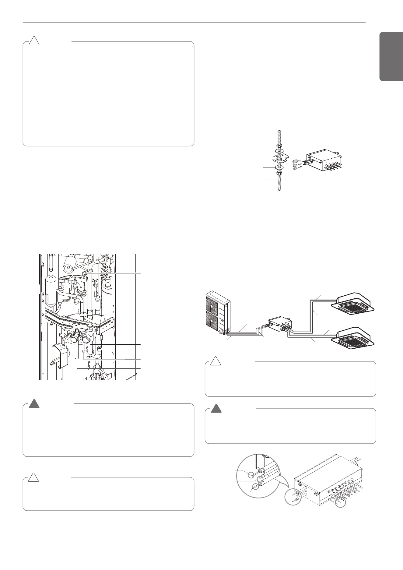
Installation procedure for HR unit
1 Using an insert-hole-in- anchor, hang the hanging bolt.
2 Install a hexagon nut and a flat washer (locally-procured)to the
hanging bolt as shown in the figure in the bottom, and fit the main
unit to hang on the hanger metal.
3 After checking with a level that the unit is level, tighten the hexa-
gon nut.
* The tilt of the unit should be within ±5° in front/back and left/right.
4 This unit should be installed suspended from ceiling and side A
should always be
facing up.
5 Insulate not used pipes completely as shown in the figure.
Installation of Outdoor Unit, HR Unit and In-
door Unit Refrigerant Pipe
3 pipes are connected to the HR unit from the outdoor unit, classified
into liquid pipe, low pressure gas pipe and high pressure gas pipe de-
pending on status of refrigerant passing through the pipe.
You must connect 3 pipes from outdoor unit to HR unit.
For connection between indoor unit and HR unit, you must connect
both liquid pipe and gas pipe from the HR unit to the indoor unit. In this
case, connect them to the indoor unit starting from No.1 connection
port of the HR unit (the port number is displayed on ports of the HR
unit). Use auxiliary flare as annexed parts in connection to the indoor
unit.
Six-sided Nut
(M10 or M8)
Hanger metal
Hanger metal
Hanger metal
Flat washer
Flat washer
Flat washer
(M10)
Hanging bolt
Hanging bolt
Hanging bolt
(M10 or M8)
A
Insulation
Gas pipe
Gas pipe
Liquid pipe
Liquid pipe
HR Unit
1
2
3
4
Low pressure
Gas pipe
Liquid pipe
High pressure
Gas pipe
Whenever connecting the indoor units with the HR unit, install the in-
door units in numerical order from No.1.
Ex) In case of installing 3 indoor units : No. 1, 2, 3 (O), No. 1, 2, 4 (X),
No.1, 3, 4 (X), No.2, 3, 4 (X).
CAUTION
!
WARNING
Before brazing work, remove gas in the HR Unit by cutting the three
pipes in the small circles on the figure.
If not, it may cause injuries.
Remove the caps before connecting pipes.
!
REFRIGERANT PIPING INSTALLATION
Precautions on Pipe connection / Valve operation
Pipe connection is done by connecting from the end of the pipe to the
branching pipes, and the refrigerant pipe coming out of the outdoor
unit is divided at the end to connect to each indoor unit and HR unit.
Flare connection for the indoor unit, and welding connection for the
outdoor pipe and the branching parts. (Including HR unit)
- Use hexagonal wrench to open/close the valve.
Gas pipe Ø15.88– Ø12.7
Liquid pipeØ9.52– Ø6.35
Brazing Type
Liquid pipe
High pressure
gas pipe
Low pressurse
gas pipe
(Brazing Type)
1,MFL69717904,영영 18. 8. 29. 영영 2:49 Page 13
14
ENGLISH
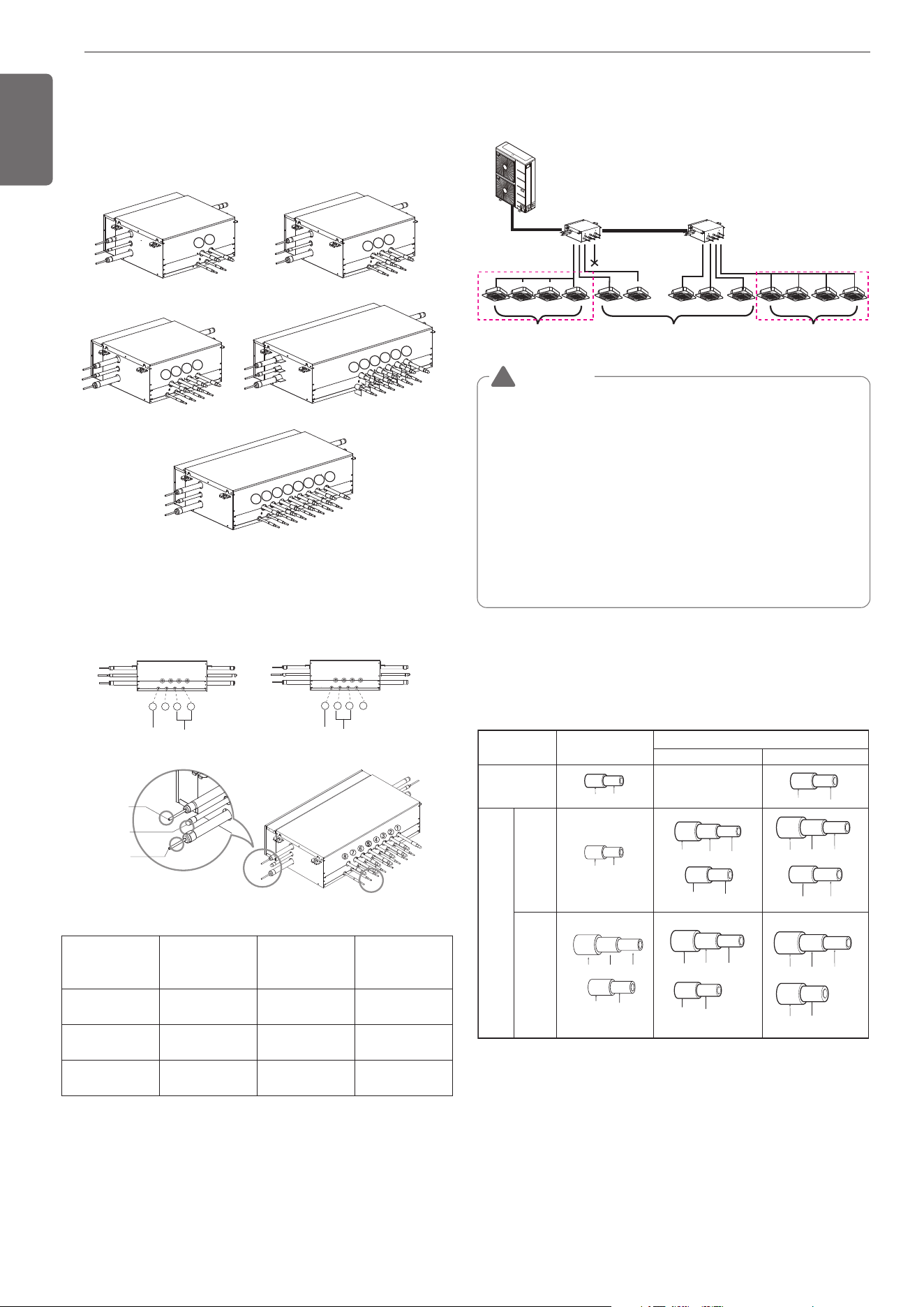
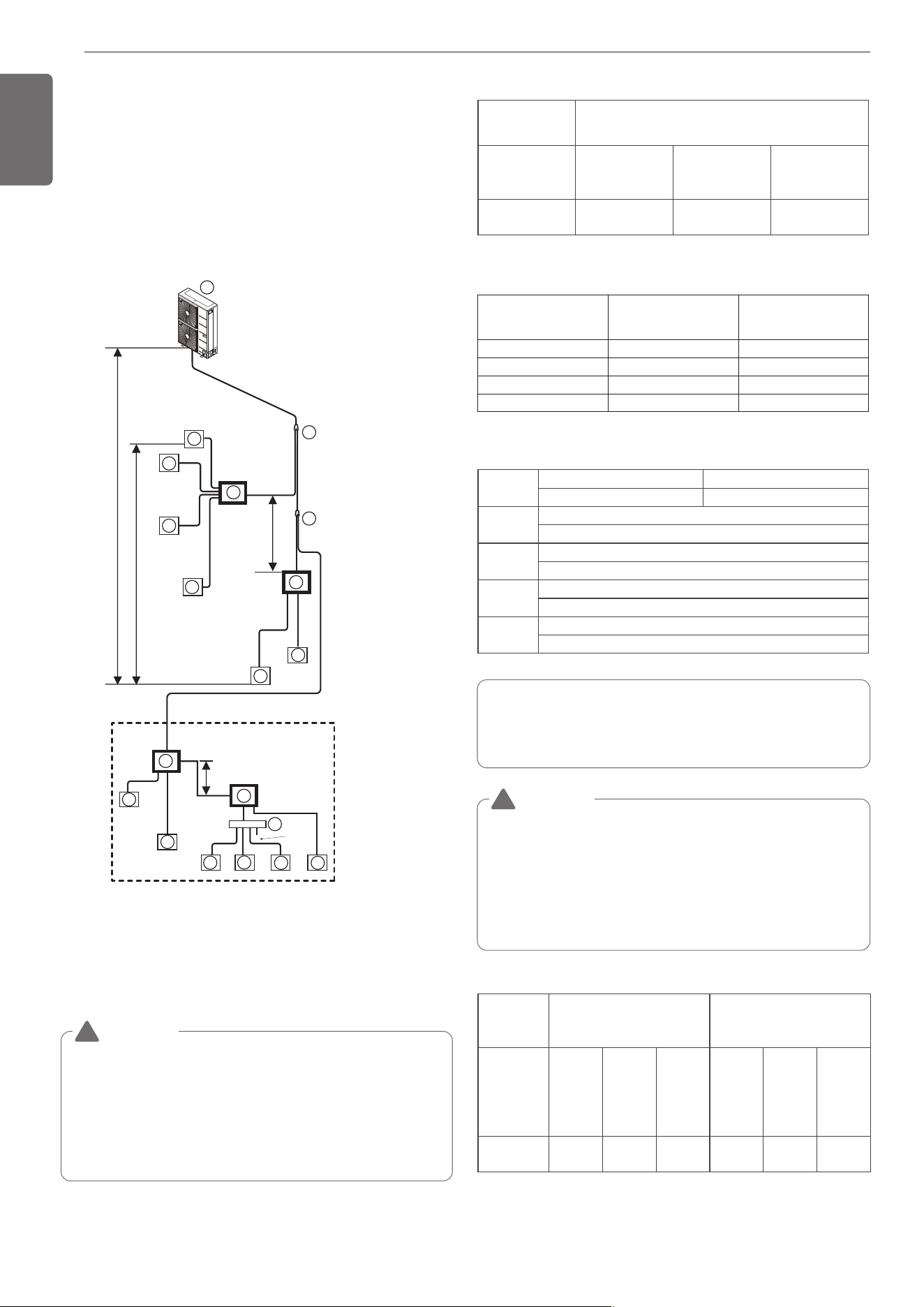
Type of HR Unit
Select an HR unit according to the number of the indoor units to be in-
stalled. HR units are classified into 3 types by the number of con-
nectable indoor units.
Ex) Installation of 10 indoor units
Consists of HR unit for 8 branches and HR unit for 2 branches.
Joint Method of HR Unit (Big Duct : ARNU76GB8-, ARNU96GB8-)
Joint Method is required when B5/B8 chassis is installed. In Joint
Method, two neighboring outlets of one HR unit are linked by Y branch
pipe and connected to one indoor unit.
Installation of Zoning Control
Some indoor unit can be connected to one port of HR unit.
For detailed instructions on installing the HR Unit, see the installation
manual included with the HR Unit.
[Reducers for indoor unit and HR unit]
Unit : mm(inch)
HR unit PRHR023(A) PRHR033(A)
PRHR043(A)
PRHR063(A)
PRHR083(A)
Low pressure
gas pipe
Ø22.2(7/8) Ø28.58(1-1/8) Ø28.58(1-1/8)
High pressure
gas pipe
Ø19.05(3/4) Ø22.2(7/8) Ø22.2(7/8)
Liquid pipe Ø9.52(3/8) Ø12.7(1/2) Ø15.88(5/8)
HR unit HR unit
sealing
Changeover under control
Auto changeover
Changeover under control
Zoning control group 1
Zoning control group 2
(Max. 8 Indoor Units)
(Max. 8 Indoor Units)
Models
High pressure
-
Gas pipe
Low pressure
Liquid pipe
Indoor unit
reducer
HR unit
reducer
PRHR023(A)
OD22.2(7/8) Ø19.05(3/4) Ø15.88(5/8)
OD15.88(5/8) Ø
12.7(1/2)
Ø6.35(1/4)OD9.52(3/8)
OD19.05(3/4) Ø15.88(5/8)
OD12.7(1/2) Ø9.52(3/8)
Ø12.7(1/2)
OD22.2(7/8) Ø19.05(3/4) Ø15.88(5/8)
OD15.88(5/8) Ø12.7(1/2)
PRHR033(A)/
PRHR043(A)/
PRHR063(A)/
PRHR083(A)
OD19.05(3/4) Ø15.88(5/8)
OD28.58(1-1/8) Ø22.2(7/8) Ø19.05(3/4)
OD15.88(5/8) Ø12.7(1/2)
Ø6.35(1/4)OD9.52(3/8)
OD12.7(1/2) Ø9.52(3/8)
OD15.88(5/8)
Ø12.7(1/2)
Ø9.52(3/8)
PRHR033(A)(3 branches)PRHR023(A)(2 branches)
PRHR063(A)(6 branches)
PRHR083(A)(8 branches)
PRHR043(A)(4 branches)
8
7
6
5
4
3
2
1
6
5
4
3
2
1
4
3
2
1
3
2
1
2
1
1
st
2 HR Unit
nd
HR Unit
4 3 2 1
BG
(38k) (92k)
B8
(48k)
BH
(72k)
B8
4 3 2 1
Gas pipe Ø15.88– Ø12.7
Liquid pipeØ9.52– Ø6.35
Brazing Type
Liquid pipe
High pressure
gas pipe
Low pressurse
gas pipe
(Brazing Type)
WARNING
• A branch pipe of HR unit allows up to 14.5kW(48kBtu/h) based on
cooling capacity of the indoor unit. (up to 14.5kW(48kBtu/h) for
max installation)
• The maximum total capacity of indoor units connected to a
PRHR042(A) HR unit is 58kW(192kBtu/h).
• The maximum number of indoor units connected to a
PRHR042(A) HR unit are 32 indoor units. (The Maximum indoor
units per a branch pipe of HR unit are 8 indoor units)
• There is not operate “Auto-changeover” & “Mode override” func-
tion in the zoning group.
• When there are operating indoor units on cooling(heating) mode,
another indoor units aren’t changed on heating(cooling) mode in
the zoning group.
!
1,MFL69717904,영영 18. 8. 29. 영영 2:49 Page 14
15
ENGLISH
- Pipe connections can be done on the front side or on the side accord-
ing to the installation environments.
- Be sure to let 0.2kgf/cm
2
(0.284lbs/in
2
) Nitrogen flow in the pipe when
welding.
- If Nitrogen was not flown during welding, many oxidized membranes
may form inside the pipe and disturb the normal operations of valves
and condensers.
Bottom Side Pipe
Draw Out
Rear Side Pipe
Draw Out
Front Pipe
Draw Out
Right Side Pipe
Draw Out
Refrigerant Pipe
Regulator
Nitrogen
Taping
Valve
Nitrogen
Nitrogen
Direction
Direction
Nitrogen
Direction
<High Pressure Gas pipe> <Low Pressure Gas pipe>
<Liquid pipe>
Wet towel
Removal Area for Liquid/Gas
pipe bottom side connections.
CAUTION
• Do not give damage to the pipe/base during the Knock Out
work.
• Proceed to pipe work after removing burr after Knock Out work.
• Perform sleeve work to prevent damage to the wire when con-
necting wires using knock Outs.
!
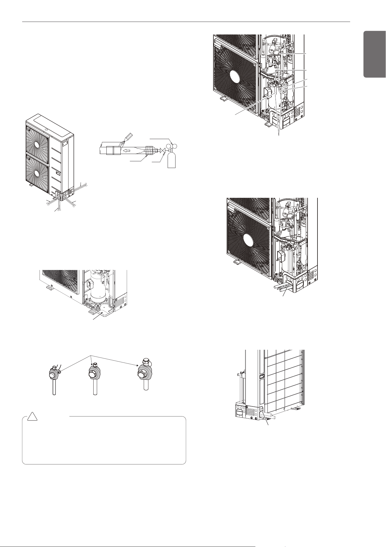
Remove leakage prevention cap
• Remove the leakage prevention cap attached to the outdoor unit
service valve before pipe work.
• Proceed the leakage prevention cap removal as follows:
- Verify whether the liquid/gas pipes are locked.
- Extract remaining refrigerant or air inside using the service port.
- Remove the leakage prevention cap
Service Port
Refrigerant
Charging Port
Liquid pipe
High Pressure gas pipe
Leakage prevention cap
Low Pressure gas pipe
Pipe Knock Out for
Liquid/Gas pipes
Method of drawing out pipes on the rear side
- Proceed with the pipe work as shown in the below figure for rear
side pie drawing out.
Pipe Knock Out for Liquid/Gas pipes
※Pictures may differ depending on the model.
Pipe Drawing Out during Single / Series connection
Method of drawing out pipes on the front side and right side
- Proceed with the pipe work as shown in the below figure for front
side and right side pipe drawing out.
Preparation Work
- Use Knock Outs of Base Pan of the outdoor unit for Left/Right or
Bottom pipe drawing outs.
- Use the wet towel as shown in the below figure before welding
PIPE CONNECTIONS BETWEEN
INDOOR AND OUTDOOR UNIT
1,MFL69717904,영영 18. 8. 29. 영영 2:49 Page 15
Refrigerant piping system
Refrigerant Pipe Connection
Example : 12 Indoor Units connected
Ⓐ : Outdoor Unit
Ⓑ : Y branch
Ⓓ : Indoor Unit
Ⓖ : Header
Ⓗ : HR Unit
Refrigerant pipe diameter from outdoor unit to first branch. (A)
* If available on site, it use this size. Otherwise it can’t be increased.
Refrigerant pipe diameter from branch to branch (B,C,D)
Total pipe length = A+B+C1+C2+C3+D+a+b+c+d+e+f+g+i+j+k+l+m+n
≤ 300m(984ft)
Refrigerant pipe diameter from outdoor unit to first branch. (A)
A1
H1
D
1
2
D
D
D
3
4
C1
B
C2
C3
*
B1
B2
a
b
c
d
e
g
j
k
x
l
m
n
sealing
f
i
H
h
"a"
“b”
D
A
H2
H4
G
H3
■ Case 1 ("a")
: Maximum height is 15m(49ft) if you install with Y branch.
■ Case 2 ("b")
: Maximum height is 5m(16ft) in serial connection of HR units.
D
5
D
6
D
7
D
8
D
10
D
9
D
11
D
12
Upward outdoor
unit total capacity
Pipe diameter
HP Liquid mm(inch)
Low pressure gas
pipe
mm(inch)
High pressure gas
pipe
mm(inch)
6
Ø9.52
(3/8)
Ø19.05
(3/4)
Ø15.88
(5/8)
Downward Indoor
Unit total capacity
[kW(Btu/h)]
Liquid pipe [mm(inch)] Gas pipe [mm(inch)]
≤ 5.6(19,100)
Ø6.35(1/4) Ø12.7(1/2)
< 16.0(54,600) Ø9.52(3/8) Ø15.88(5/8)
≤ 22.4(76,400)
Ø9.52(3/8) Ø19.05(3/4)
< 36.4(124,200) Ø9.52(3/8) Ø22.2(7/8)
L
Longest pipe length *Equivalent pipe length
A+B+C3+D+k ≤150m(492ft) A+B+C3+D+k ≤175m(574ft)
l
Longest pipe length after 1st branch
B+C+D+e ≤ 40m(131ft)
H
Difference in height (Outdoor Unit ÷ Indoor Unit)
H ≤ 50m(164ft)
h
Difference in height (Indoor Unit ÷ Indoor Unit)
h ≤ 15m(49ft)
"a", "b"
Difference in height(HR unit ÷ HR unit)
a ≤ 15m(49ft) , b ≤ 5m(16ft)
Upward
outdoor unit
total capacity
Pipe diameter
Pipe diameter when pipe
length is ≥ 90m(295 ft)
HP
Liquid
mm(inch)
Low pres-
sure gas
pipe
mm(inch)
High pres-
sure gas
pipe
mm(inch)
Liquid
mm(inch)
Low pres-
sure gas
pipe
mm(inch)
High pres-
sure gas
pipe
mm(inch)
6
Ø9.52
(3/8)
Ø19.05
(3/4)
Ø15.88
(5/8)
Ø 12.7
(1/2)
Ø 22.2
(7/8)
Ø 19.05
(3/4)
16
ENGLISH
WARNING
• Refer to the HR unit PCB part for the valve group control setting.
• It is recommended that difference in pipe lengths between an HR
unit and indoor units, for example difference in length of a, b, c,
and d, be minimized. The larger difference in pipe lengths, the
more different performance between indoor units.
* If the large capacity indoor units (Over 5 HP; using over
Ø15.88(5/8)/9.52(3/8) are installed, it should be used the Valve
Group setting
!
• * : Assume equivalent pipe length of Y branch to be 500mm(19-
5/8inch), that of header to be 1000mm(39-1/4inch), calculation pur-
pose
• It is recommended that indoor unit is installed at lower position
than the header.
WARNING
When the any one (or both) of below conditions are satisfied, the
diameter of main pipe (A) must be increased according to below
table.
- The equivalent length between outdoor unit and the farthest in-
door unit is 90m(295ft) or more (Liquid, High pressure gas pipes
and Low pressure gas pipes are increased)
- The level difference (Outdoor unit ↔ Indoor unit) is 50m(164ft) or
more (Only liquid pipe is increased)
!
1,MFL69717904,영영 18. 8. 29. 영영 2:49 Page 16
17
ENGLISH
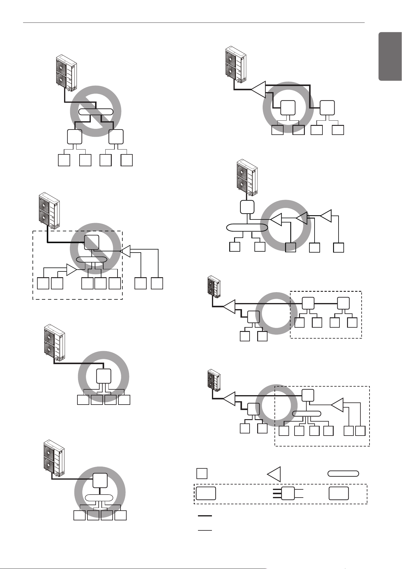
Y branch, Header and HR unit connection pattern
Pattern 1
Pattern 2
Pattern 3
HR1
HR1
14.5kW
(48kBtu/h)
14.5kW
(48kBtu/h)
14.5kW
(48kBtu/h)
14.5kW
(48kBtu/h)
1
1
2
234567
HR2
2.1kW
(7kBtu/h)
2.1kW
(7kBtu/h)
2.1kW
(7kBtu/h)
2.1kW
(7kBtu/h)
2.1kW
(7kBtu/h)
7.25kW
(24kBtu/h)
7.25kW
(24kBtu/h)
3 4
B
HR1
1 2 3 4
Pattern 4
1 2 3 4
• The maximum total capacity of indoor
units is 58kW(192 kBtu/h).
• The maximum total capacity of a branch
pipe of HR unit is 14.5kW(48 kBtu/h).
• Impossible installation : Head branch pipe → HR unit
• Impossible installation : HR unit → Head branch
pipe → Y and Head branch pipe.
HR1
B
B
A
14.5kW
(48kBtu/h)
3.63kW
(12kBtu/h)
3.63kW
(12kBtu/h)
3.63kW
(12kBtu/h)
3.63kW
(12kBtu/h)
14.5kW
(48kBtu/h)
14.5kW
(48kBtu/h)
14.5kW
(48kBtu/h)
Pattern 5
HR1
HR1
A
B
1 2
HR2
3 4
Pattern 6
A
A
A
12 345
14.5kW
(48kBtu/h)
7.25kW
(24kBtu/h)
7.25kW
(24kBtu/h)
3.63kW
(12kBtu/h)
3.63kW
(12kBtu/h)
7.25kW
(24kBtu/h)
14.5kW
(48kBtu/h)
14.5kW
(48kBtu/h)
14.5kW
(48kBtu/h)
Pattern 7
Pattern 8
HR1
A
A
A
1 2
• * : Serial connection of HR units : Capacity sum of indoor units ≤ 192 kBtu/h
• * : Maximum indoor units
p
er a branch are 8 indoor units
HR2
3 4
HR3
5 6
*
HR1
1 2
HR2
*
B
3 4 5 6 7 8
14.5kW
(48kBtu/h)
14.5kW
(48kBtu/h)
14.5kW
(48kBtu/h)
14.5kW
(48kBtu/h)
14.5kW
(48kBtu/h)
14.5kW
(48kBtu/h)
14.5kW
(48kBtu/h)
14.5kW
(48kBtu/h)
3.63kW
(12kBtu/h)
3.63kW
(12kBtu/h)
3.63kW
(12kBtu/h)
3.63kW
(12kBtu/h)
7.25kW
(24kBtu/h)
7.25kW
(24kBtu/h)
• Pipe installation from outdoor units to HR units
: 3 pipes(Low pressure Gas pipe, High pressure Gas pipe, Liquid pipe)
• Pipe installation from HR units to indoor units
: 2 pipes(Gas pipe, Liquid pipe)
B
A
1
HR1
Outdoor
Unit
Indoor Unit Y Branch pipe
Low pressure Gas pipe
High pressure Gas pipe
Liquid pipe
Gas pipe
Liquid pipe
Head Branch pipe
Indoor
Unit
1,MFL69717904,영영 18. 8. 29. 영영 2:49 Page 17
18
ENGLISH
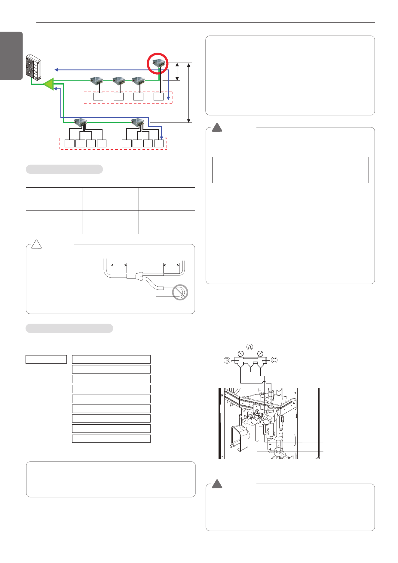
• Keep the 40m(131ft) distance from the first branch to the farthest in-
door.
1) under 40m(131ft)
Keep the sum of indoor capacity under 58kW(192 kBtu/h).
Indoor
Unit
Indoor
Unit
Indoor
Unit
Indoor
Unit
Indoor
Unit
Indoor
Unit
Indoor
Unit
Indoor
Unit
Indoor
Unit
Indoor
Unit
Indoor
Unit
Indoor
Unit
1) under 40m(131ft)
Y branch
5m(16ft)
15m(49ft)
Keep the sum of indoor capacity under 58kW(192 kBtu/h).
Indoor Unit Connection
Indoor Unit connecting pipe from branch (a,b,c,d,e,f)
Indoor Unit capacity
[kW(Btu/h)]
Liquid pipe
[mm(inch)]
Gas pipe [mm(inch)]
≤ 5.6(19,100)
Ø6.35(1/4) Ø12.7(1/2)
< 16.0(54,600) Ø9.52(3/8) Ø15.88(5/8)
< 22.4(76,400) Ø9.52(3/8) Ø19.05(3/4)
< 28.0(95,900) Ø9.52(3/8) Ø22.2(7/8)
CAUTION
• Bending radius should be
at least twice the diameter
of the pipe.
• Bend pipe after 500mm
(19-5/8inch) or more from
branch(or header).
Do not bend U type.
It may cause Performance
unsatisfactory or noise.
!
500mm
(19-5/8inch)
or more
500mm
(19-5/8inch)
or more
The amount of Refrigerant
The calculation of the additional charge should take into account the
length of pipe and CF(correction Factor) value of indoor unit.
Amount refrigerant of Indoor units
Example) 4Way Ceiling Cassette 14.5kW -1ea, Ceiling concealed
Duct 7.3kW-2ea, Wall Mounted 2.3kW-4ea
CF = 0.64 × 1 + 0.26 × 2 + 0.24 × 4 = 2.12kg(4.67lbs)
Attach the additional refrigerant table of IDU.
Additional charge(kg) = Total liquid pipe : Ø25.4 mm (1.0 inch) x
0.480 kg/m (0.323 lbs/ft)
+ Total liquid pipe : Ø22.2 mm (7/8 inch) x
0.354 kg/m (0.238 lbs/ft)
+ Total liquid pipe : Ø19.05 mm (3/4 inch) x
0.266 kg/m (0.179 lbs/ft)
+ Total liquid pipe : Ø15.88 mm (5/8 inch) x
0.173 kg/m (0.116 lbs/ft)
+ Total liquid pipe : Ø12.7 mm (1/2inch) x
0.118 kg/m (0.079 lbs/ft)
+ Total liquid pipe : Ø9.52 mm (3/8inch) x
0.061 kg/m (0.041 lbs/ft)
+ Total liquid pipe : Ø6.35 mm (1/4 inch) x
0.022 kg/m (0.015 lbs/ft)
+ Number of installed HR unit x
0.5 kg (1.1 lbs)
+ CF value of indoor unit
WARNING
• Regulation for refrigerant leakage
: the amount of refrigerant leakage should satisfy the following
equation for human safety.
If the above equation can not be satisfied, then follow the follow-
ing steps.
• Selection of air conditioning system: select one of the next
- Installation of effective opening part
- Reconfirmation of Outdoor Unit capacity and piping length
- Reduction of the amount of refrigerant
- Installation of 2 or more security device (alarm for gas leakage)
• Change Indoor Unit type
:
installation position should be over 2m(6.6ft) from the floor (Wall
mounted type ’ Cassette type)
• Adoption of ventilation system
: choose ordinary ventilation system or building ventilation sys-
tem
• Limitation in piping work
: Prepare for earthquake and thermal stress
Liquid pipe
High Pressure gas pipe
Low Pressure gas pipe
Ⓐ Manifold Gauge
Ⓑ Low pressure side Handle
Ⓒ High pressure side Handle
!
WARNING
• Pipe to be vacuumed : gas pipe, liquid pipe
• If the refrigerant amount is not exact, it may not operate
properly.
• If additionally bottled refrigerant amount is over 10%, condenser
burst or insufficient indoor unit performance may be caused.
!
Volume of the room at which Indoor Unit of
the least capacity is installed
Total amount of refrigerant in the system
≤0.44kg/m
3
(0.028lbs/ft
3
)
Refrigerant charging
※6 & 8 Branches Model :
1.0kg/EA (2.2 lbs/EA)
1,MFL69717904,영영 18. 8. 29. 영영 2:49 Page 18
19
ENGLISH
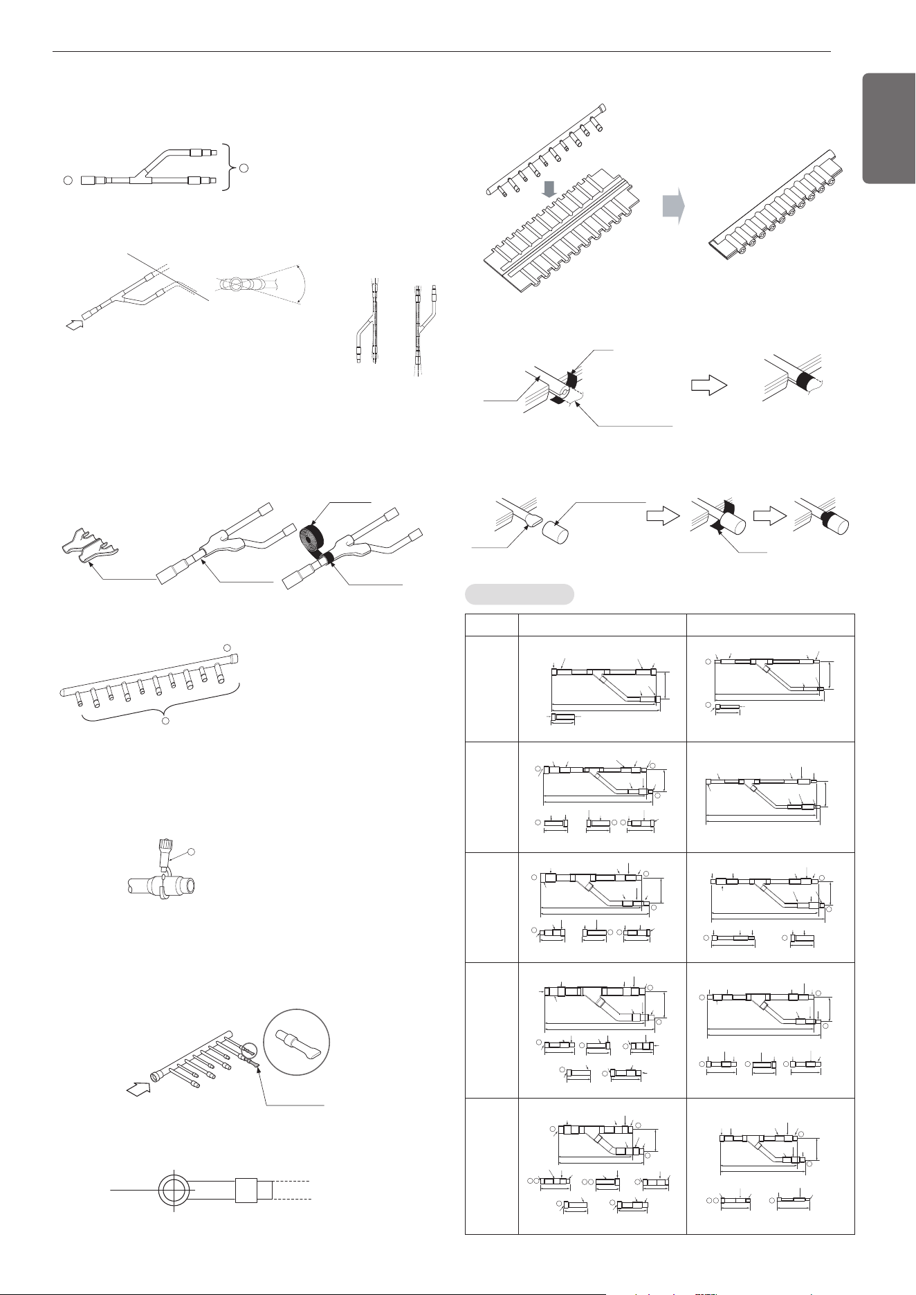
• When the number of indoor units to be connected to the branch
pipes is less than the number of branch pipes available for connec-
tion then cap pipes should be fitted to the surplus branches.
• Fit branch pipe lie in a horizontal plane.
Pinched pipe
B
Horizontal plane
View from point B in the direction of the arrow
Header
Insulator
(included with kit)
Liquid and gas
pipe joints
Insulator for
field piping
Tape
(field supply)
A
B
C
• There is no limitation on the joint mounting configuration.
• If the diameter of the refrigerant piping selected by the procedures
described is different from the size of the joint, the connecting sec-
tion should be cut with a pipe cutter.
• Branch pipe should be insulated with the insulator in each kit.
Ⓐ To Outdoor Unit
Ⓑ To Indoor Unit
• The indoor unit having larger ca-
pacity must be installed closer
to Ⓐ than smaller one.
• If the diameter of the refrigerant
piping selected by the proce-
dures described is different
from the size of the joint, the
connecting section should be
cut with a pipe cutter.
ⓒ Pipe cutter
• When the number of pipes to be
connected is smaller than the
number of header branches, in-
stall a cap to the unconnected
branches.
Y branch
A
B
Facing
upwards
Facing
downwards
Within ±3° Within ±3°
Viewed from point A
in direction of arrow
Horizontal
plane
Within +/- 10°
A
Ⓐ
To Branch Piping or Indoor Unit
Ⓑ To Outdoor Unit
• Ensure that the branch pipes are attached horizontally or vertically
(see the diagram below.)
Branch pipe Fitting
• Joints between branch and pipe should be sealed with the tape in-
cluded in each kit.
• Any cap pipe should be insulated using the insulator provided with
each kit and then taped as described above.
Insulator
Insulator of field pipe
Tape
Tape
Cap pipe
Insulator for cap pipe
Y branch pipe
Models Gas pipe Liquid pipe
ARBLN
01621
I.D19.05(3/4)
O.D15.88(5/8 )
I.D12.7(1/2)
I.D15.88(5/8)
I.D15.88(5/8)
I.D15.88(5/8)
I.D12.7(1/2)
I.D12.7(1/2)
292(11-1/2)
281(11-1/16)
74
(2-29/ 32)
70(2- 3 /4)
1
1
I.D12.7(1/2)
292(11-1/2)
281(11-1/16)
74
(2-29/ 32)
70(2- 3 /4)
I.D6.35(1/4)
I.D6.35(1/4)
I.D6.35(1/4) I.D9.52(3 / 8)
I.D9.52(3 / 8 )
I.D9.52(3 / 8 )
O.D9.52(3/8)
ARBLN
03321
1
2
3
3 1 2
I.D19.05(3/4)
I.D25.4(1)
I.D22.2(7/8)
I.D19.05(3/4) I.D12.7(1/2)I.D15.88(5/8)
83
(3-9 / 32)
I.D19.05(3/4)
I.D12.7
(1/2)
I.D15.88(5/8)
70(2- 3 /4)
O.D19.05(3/4) I.D22.2(7/ 8)
O.D25. 4(1)
I.D28.58(1-1/8 )
80(3-5/32)
I.D25.4(1)
110(4- 11/32)
O.D19.05(3/4)
I.D22.2(7/8)
413(16-1/4)
390(15-11/32)
I.D12.7(1/2)
I.D12.7(1/2)
I.D12.7(1/2)
74
(2-29/ 32)
332(13-1/16)
321(12-5/8)
I.D6.35(1/4)
I.D6.35(1/4)
I.D9.52(3 / 8 )
I.D9.52(3 / 8 )
I.D9.52(3 / 8 )
ARBLN
07121
2
3
1
2
1 3
I.D12.7
(1/2)
376(14-13/16)
404(15-29/32)
120(4-23/32) 120(4-23/32)
90(3-17/32)
I.D15.88(5/8)
I.D15.88(5/8)
I.D19.05(3/4)
I.D19.05(3/4)
O.D19.05(3/4)
96
(3-25/32)
I.D22.2(7/8)
I.D22.2(7/8)
O.D22.2
(7/8)
I.D34.9(1-3/ 8 )
I.D28.58(1-1/8 )
I.D28.58(1-1/8 )
I.D28.58(1-1/8 )
O.D31.8(1- 1/4)I.D31.8(1-1/4)
I.D31.8(1-1/4)
2
3
3 2
I.D15.88(5/8)
I.D15.88(5/8)
I.D15.88(5/8)I.D12.7(1/2)
I.D12.7(1/2)
I.D12.7(1/2)
O.D12.7(1/2)
O.D12.7(1/2)
70(2- 3 /4)
110(4- 11/32)
371(14-19 / 32)
394(15- 1/2)
83
(3-9 / 32)
I.D19.05(3/4)
I.D19.05(3/4)
I.D19.05(3/4)
I.D6.35(1/4)I.D9.52(3 / 8 ) I.D9.52(3/8)
ARBLN
14521
2
3
3
3
2
2
3
471(18-17 /32)
517(20-11/32)
125
(4-29/32)
I.D41.3(1-5/8)
I.D38.1(1-1/2)
I.D38.1(1-1/2)
I.D22.2
(7/8)
I.D34.9(1-3/ 8 )
I.D34.9(1-3/ 8 )
I.D34.9
(1-3/8)
I.D28.58(1-1/8 )
I.D28.58(1-1/8 )
I.D15.88(5/8)
120(4-23/32)
I.D19.05(3/4)
O.D22.2
(7/8)
I.D41.3(1-5/8)
O.D38.1(1-1/2)
90(3-17/32)
130(5-1/ 8)
I.D41.3
(1-5/8)
I.D38.1(1-1/2)
O.D34.9(1- 3 / 8 )
I.D12.7(1/2)
I.D22.2(7/8)
O.D28.58(1- 1/ 8 )
70(2- 3 /4)
O.D15.88(5/8 )
120(4-23/32)
I.D19.05(3/4)
2
3
1
2 3 3
I.D15.88(5/8) I.D19.05(3/4)
I.D22.2(7/8)
I.D15.88(5/8)
I.D19.05(3/4)
I.D22.2(7/8)
I.D12.7
(1/2)
96
(3-25/32)
I.D15.88(5/8)
I.D19.05(3/4)
41616-3/8)
444(17-15/32)
I.D12.7(1/2)
O.D12.7(1/2)
O.D15.88(5/8 )
O.D19.05(3/4)
I.D22.2(7/8)
I.D6.35(1/4)
I.D9.52(3 / 8 )
I.D9.52(3 / 8 )
110(4- 11/32)110(4- 11/32) 80(3-5/32)
ARBLN
23220
115(4-17/32)
X2
100(3-15/16)
I.D12.7(1/2)
70(2-3/4)
120(4-23/32)
O.D.38.1(1-1/2)
I.D.34.9(1-3/8)
I.D.28.58(1-1/8)
O.D.28.58(1-1/8)
O.D.44.48(1-3/4)
X2
175(6-7/8)
I.D.53.98(2-1/4) I.D.25.4(1)
I.D.53.98(2-1/4) I.D41.3(1-5/8)
I.D41.3(1-5/8)
I.D38.1(1-1/2)
I.D38.1(1-1/2)
I.D.44.48(1-3/4)
I.D.44.48(1-3/4)
I.D.44.48(1-3/4)
420(16-17/32)
490(19-9/32)
134
(5-17/32)
1
2
3
32
3 3
3
3
2
I.D31.8(1-1/4)
O.D22.2(7/ 8)
I.D22.2(7/8)
I.D15.88(5/8)
O.D15.88(5/8 )
I.D19.05(3/4)
I.D12.7(1/2) O.D12.7(1/2) I.D6.35(1/4)
I.D9.52(3/8)
X2
110(4-11/32) 110(4-11/32)
I.D.25.4(1)
I.D.25.4(1)
I.D.25.4(1)
346(13-5/8)
379(14-29/32)
96
(3-25/32)
2
3 32
3
I.D22.2(7/8)
I.D22.2(7/8)
I.D22.2(7/8)
I.D15.88(5/8)
O.D19.05(3/4)
I.D19.05(3/4)
I.D19.05
(3/4)
[Unit:mm(inch)]
• Header should be insulated with the insulator in each kit.
Insulate the header using
the insulation
material attached to the
branch pipe kit
as shown in the figure.
1,MFL69717904,영영 18. 8. 29. 영영 2:49 Page 19
20
ENGLISH
[Unit:mm(inch)]
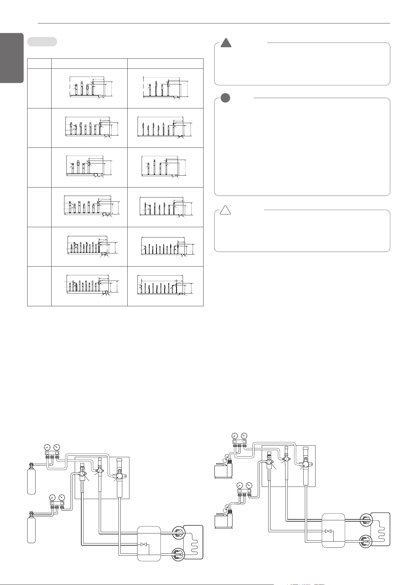
Leak test
Leak test should be made by pressurizing nitrogen gas to 3.8
MPa(551.1psi). If the pressure does not drop for 24 hours, the system
passes the test. If the pressure drops, check where the nitrogen leaks.
For the test method, refer to the following figure. (Make a test with
the service valves closed. Be also sure to pressurize liquid pipe, gas
pipe and high/low pressure common pipe)
The test result can be judged good if the pressure has not be reduced
after leaving for about one day after completion of nitrogen gas pres-
surization.
Indoor unit
Nitrogen gas
cylinder
Nitrogen gas
cylinder
Outdoor unit
High Pressure
Gas pipe
Liquide pipe
Low Pressure
Gas pipe
Liquid side
Gas side
Close
Close
Close
HR unit
Header
Models Gas pipe Liquid pipe
4 branch
ARBL054
ID9.52(3/8)
ID6.35(1/4)
ID9.52(3/8)
ID6.35(1/4)
ID9.52(3/8)
ID6.35(1/4)
ID15.88(5/8)
ID12.7(1/2)
ID12.7(1/2)
ID15.88(5/8)
360(14-5/32)
120(4-23/32)
ID12.7(1/2)
ID15.88(5/8)
150
(5-29/32)
120
(4-23/32)
ID15.88(5/8)ID19.05(3/4)
ID9.52(3/8)
ID6.35(1/4)
150
(5-29/32)
120
(4-23/32)
ID9.52(3/8)
ID6.35(1/4)
360(14-5/32)
ID6.35(1/4)
120(4-23/32)
ID9.52(3/8)
ID9.52(3/8)ID12.7(1/2)
ID9.52(3/8)
ID6.35(1/4)
ID9.52(3/8)
ID6.35(1/4)
ID15.88(5/8)
ID12.7(1/2)
7 branch
ARBL057
ID9.52(3/8)
ID6.35(1/4)
ID9.52(3/8)
ID6.35(1/4)
ID9.52(3/8)
ID6.35(1/4)
ID15.88(5/8)
ID12.7(1/2)
120(4-23/32)
150
(5-29/32)
120
(4-23/32)
ID15.88(5/8)
540(21-1/4)
ID15.88(5/8)
ID12.7(1/2)
ID15.88(5/8)ID19.05(3/4)
ID12.7(1/2)
ID9.52(3/8)
ID6.35(1/4)
150
(5-29/32)
120
(4-23/32)
120(4-23/32)
ID9.52(3/8)
ID9.52(3/8)ID12.7(1/2)
540(21-1/4)
ID6.35(1/4)
ID9.52(3/8)
ID6.35(1/4)
ID9.52(3/8)
ID6.35(1/4)
ID15.88(5/8)
ID12.7(1/2)
4 branch
ARBL104
ID9.52(3/8)
ID6.35(1/4)
ID9.52(3/8)
ID6.35(1/4)
ID9.52(3/8)
ID6.35(1/4)
150
(5-29/32)
120
(4-23/32)
ID15.88(5/8)
ID15.88(5/8)ID15.88(5/8)
ID12.7(1/2)ID12.7(1/2)
ID15.88(5/8)
ID12.7(1/2)
400(15-23/32)
160(6-5/16)
ID19.05(3/4)
ID22.2(7/8)ID28.58(1-1/8)
ID25.4(1)
150
(5-29/32)
120
(4-23/32)
ID9.52(3/8)ID9.52(3/8)
ID6.35(1/4)ID6.35(1/4)
ID9.52(3/8)
ID6.35(1/4)
360(14-5/32)
ID6.35(1/4)
120(4-23/32)
ID9.52(3/8)
ID9.52(3/8)ID12.7(1/2)
ID9.52(3/8)
ID6.35(1/4)
ID9.52(3/8)
ID6.35(1/4)
ID15.88(5/8)
ID12.7(1/2)
7 branch
ARBL107
ID9.52(3/8)
ID6.35(1/4)
ID9.52(3/8)
ID6.35(1/4)
ID9.52(3/8)
ID6.35(1/4)
ID15.88(5/8)
ID12.7(1/2)
150
(5-29/32)
120
(4-23/32)
ID15.88(5/8)
ID15.88(5/8)
ID12.7(1/2)
160(6-5/16)
ID19.05(3/4)
ID22.2(7/8)ID28.58(1-1/8) ID25.4(1)
580(22-27/32)
ID9.52(3/8)
ID6.35(1/4)
150
(5-29/32)
120
(4-23/32)
ID9.52(3/8)ID9.52(3/8)
ID6.35(1/4)ID6.35(1/4)
ID9.52(3/8)
ID6.35(1/4)
120(4-23/32)
ID9.52(3/8)
ID9.52(3/8)ID12.7(1/2)
700(27-9/16)
ID6.35(1/4)
ID9.52(3/8)
ID6.35(1/4)
ID15.88(5/8)
ID12.7(1/2)
10 branch
ARBL1010
ID9.52(3/8)
ID6.35(1/4)
ID9.52(3/8)
ID6.35(1/4)
ID9.52(3/8)
ID6.35(1/4)
ID15.88(5/8)
ID12.7(1/2)
150
(5-29/32)
120
(4-23/32)
ID15.88(5/8)
ID15.88(5/8)
ID12.7(1/2)
160(6-5/16)
ID19.05(3/4)
ID22.2(7/8)ID28.58(1-1/8) ID25.4(1)
760(29-28/32)
ID9.52(3/8)
ID6.35(1/4)
ID9.52(3/8)
ID6.35(1/4)
150
(5-29/32)
120
(4-23/32)
ID9.52(3/8)
ID6.35(1/4)
120(4-23/32)
ID9.52(3/8) ID9.52(3/8)ID12.7(1/2)
ID6.35(1/4)
720(28-11/32)
ID9.52(3/8)
ID6.35(1/4)
ID15.88(5/8)
ID12.7(1/2)
10 branch
ARBL2010
ID9.52(3/8)
ID6.35(1/4)
ID9.52(3/8)
ID6.35(1/4)
ID9.52(3/8)
ID6.35(1/4)
ID15.88(5/8)
ID12.7(1/2)
150
(5-29/32)
120
(4-23/32)
ID15.88(5/8)
ID15.88(5/8)
ID12.7(1/2)
ID19.05(3/4)
ID22.2(7/8)ID28.58(1-1/8) ID25.4(1)
775(30-17/32)
182(7-5/32)
ID9.52(3/8)
ID6.35(1/4)
ID9.52(3/8)
ID6.35(1/4)
150
(5-29/32)
120
(4-23/32)
ID9.52(3/8)ID9.52(3/8)
ID6.35(1/4)ID6.35(1/4)
ID9.52(3/8)
ID6.35(1/4)
ID9.52(3/8) ID9.52(3/8)ID12.7(1/2)
ID6.35(1/4)
700(27-9/16)
60*9=540(21-1/2)
107(4-7/32)
ID15.88(5/8)
ID12.7(1/2)
Leak Test and Vacuum drying
NOTE
!
If the ambient temperature differs between the time when pressure is applied
and when the pressure drop is checked, apply the following correction factor
There is a pressure change of approximately 0.01Mpa(1.5psi) for each 33.8°F
of temperature difference.
Correction = (Temp. at the time of pressurization – Temp. at the time of
check) X 0.1
For example: Temperature at the time of pressurization
3.8MPa(551psi) is 80.6°F
24 hour later : 3.73MPa(541psi), 68°F
In this case the pressure drop of 0.07MPa(10psi) is
because of temperature drop
And hence there is no leakage in pipe occurred.
CAUTION
To prevent the nitrogen from entering the refrigeration system in
the liquid state, the top of the cylinder must be at higher position
than the bottom when you pressurize the system.
Usually the cylinder is used in a vertical standing position.
!
WARNING
Use a vacuum pump or Inert(nitrogen) gas when doing leakage test
or air purge. Do not compress air or Oxygen and do not use Flamma-
ble gases. Otherwise, it may cause fire or explosion.
- There is the risk of death, injury, fire or explosion.
!
Vacuum
Vacuum drying should be made from the service port provided on the outdoor
unit’s service valve to the vacuum pump commonly used for liquid pipe, gas
pipe and high/low pressure common pipe. (Make Vacuum from liquid pipe, gas
pipe and high/low pressure common pipe with the service valve closed.)
* Never perform air purging using refrigerant.
• Vacuum drying: Use a vacuum pump that can evacuate to -100.7kPa
(-14.6psi, 5Torr, -755mmHg).
- Evacuate the system from the liquid and gas pipes with a vacuum
pump for over 2 hrs and bring the system to -100.7kPa(-14.6psi).
After maintaining system under that condition for over 1 hr, confirm
the vacuum gauge rises. The system may contain moisture or leak.
- Following should be executed if there is a possibility of moisture re-
maining inside the pipe.
(Rainwater may enter the pipe during work in the rainy season or over
a long period of time)
After evacuating the system for 2 hrs, give pressure to the system to
0.05MPa(7.3psi)(vacuum break) with nitrogen gas and then evacuate
it again with the vacuum pump for 1hr to -100.7kPa(-14.6psi)(vacuum
drying). If the system cannot be evacuated to -100.7kPa(-14.6psi)
within 2 hrs, repeat the steps of vacuum break and its drying. Finally,
check if the vacuum gauge does not rise or not, after maintaining the
system in vacuum for 1 hr.
Scale
Use a graviometer. (One that can measure
down to 0.1kg(0.22lbs)). If you are unable
to prepare such a high-precision
gravimeter you may use a charge cylinder.
Indoor unit
Outdoor unit
High Pressure
Gas pipe
Liquide pipe
Low Pressure
Gas pipe
Liquid side
Gas side
Close
Close
Close
Vacuum
pump
Vacuum
pump
HR unit
1,MFL69717904,영영 18. 8. 29. 영영 2:49 Page 20
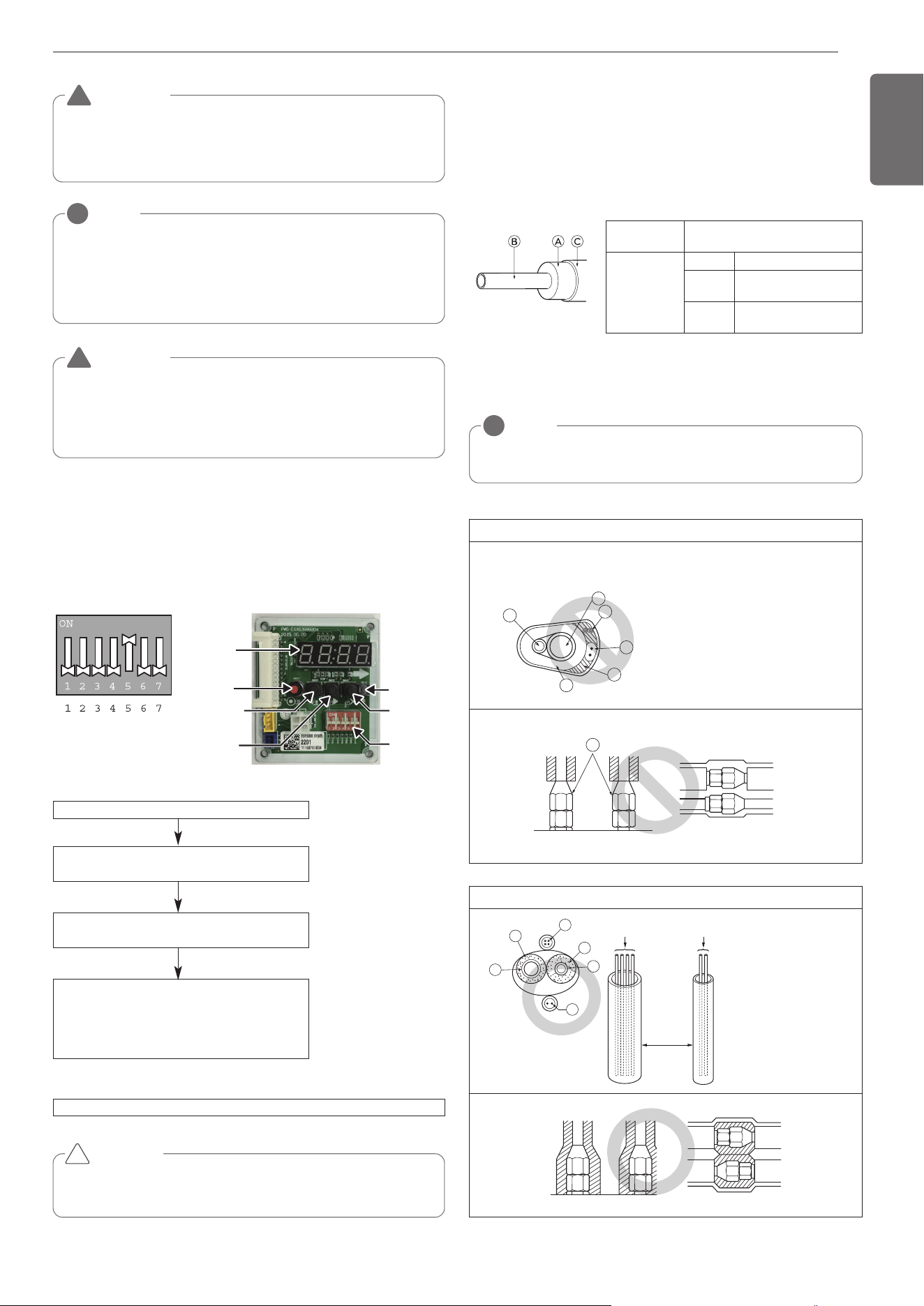
21
ENGLISH
Be sure to give insulation work to refrigerant piping by covering liquid
pipe and gas pipe separately with enough thickness heat-resistant poly-
ethylene, so that no gap is observed in the joint between indoor unit
and insulating material, and insulating materials themselves. When in-
sulation work is insufficient, there is a possibility of condensation drip,
etc. Pay special attention to insulation work to ceiling plenum.
Ⓐ Heat insulation material
Ⓑ Pipe
Ⓒ Outer covering(Wind the connection part and cutting part of heat in-
sulation material with a finishing tape.)
Heat insulation
material
Adhesive + Heat - resistant poly-
ethylene foam + Adhesive tape
Outer
covering
Indoor Vinyl tape
Floor ex-
posed
Water-proof hemp cloth +
Bronze asphalt
Outdoor
Water-proof hemp cloth +
Zinc plate + Oily paint
NOTE
!
When using polyethylene cover as covering material, asphalt roof-
ing shall not be required.
Bad example
• Do not insulate gas or low pressure pipe and liquid or highpres-
sure pipe together.
• Be sure to fully insulate connecting portion.
Ⓐ
These parts are not insulated.
Ⓐ Liquid pipe
Ⓑ Gas pipe
ⓒ Power lines
ⓓ
Finishing tape
ⓔ
Insulating material
ⓕ
Communication lines
A
C
D
E
B
F
A
Good example
Ⓐ Liquid pipe
Ⓑ Gas pipe
ⓒ Power lines
ⓓ
Insulating material
ⓔ
Communication lines
Communication lines
Separation
Power lines
E
D
D
B
A
C
Thermal insulation of refrigerant piping
NOTE
!
Always add an appropriate amount of refrigerant. (For the refrigerant addi-
tional charge)
Too much or too little refrigerant will cause trouble.
To use the Vacuum Mode
(If the Vacuum mode is set, all valves of Indoor units and Outdoor units will
be opened.)
WARNING
Use a vacuum pump or Inert(nitrogen) gas when doing leakage test
or air purge. Do not compress air or Oxygen and do not use Flamma-
ble gases. Otherwise, it may cause fire or explosion.
- There is the risk of death, injury, fire or explosion.
!
WARNING
When installing and moving the air conditioner to another site,
recharge after perfect evacuation.
- If a different refrigerant or air is mixed with the original refriger-
ant, the refrigerant cycle may malfunction and the unit may be
damaged.
!
This function is used for creating vacuum in the system after compres-
sor replacement, ODU parts replacement or IDU addition/replacement.
Vacuum mode setting method
Vacuum mode off method
CAUTION
ODU operation stops during vacuum mode. Compressor can't
operate.
Service PCB DIP switch on : No.5
Select the mode using ‘▶’, ‘◀’ Button :
“SVC” Push the ‘●’ button
Select the Function using ‘▶’, ‘◀’ Button :
“Se3” Push the ‘●’ button
Start the vacuum mode : “VACC”
ODU V/V open
ODU EEV open
IDU EEV open
Dip switch off and push the reset button on Service PCB
!
DIP-SWITCH
SW01D
(reset)
SW04C
(x:cancel)
7-Segment
SW03C
(▶:forward)
SW02C
(◀:backward)
SW01C
(●:confirm)
Vacuum Mode
1,MFL69717904,영영 18. 8. 29. 영영 2:49 Page 21
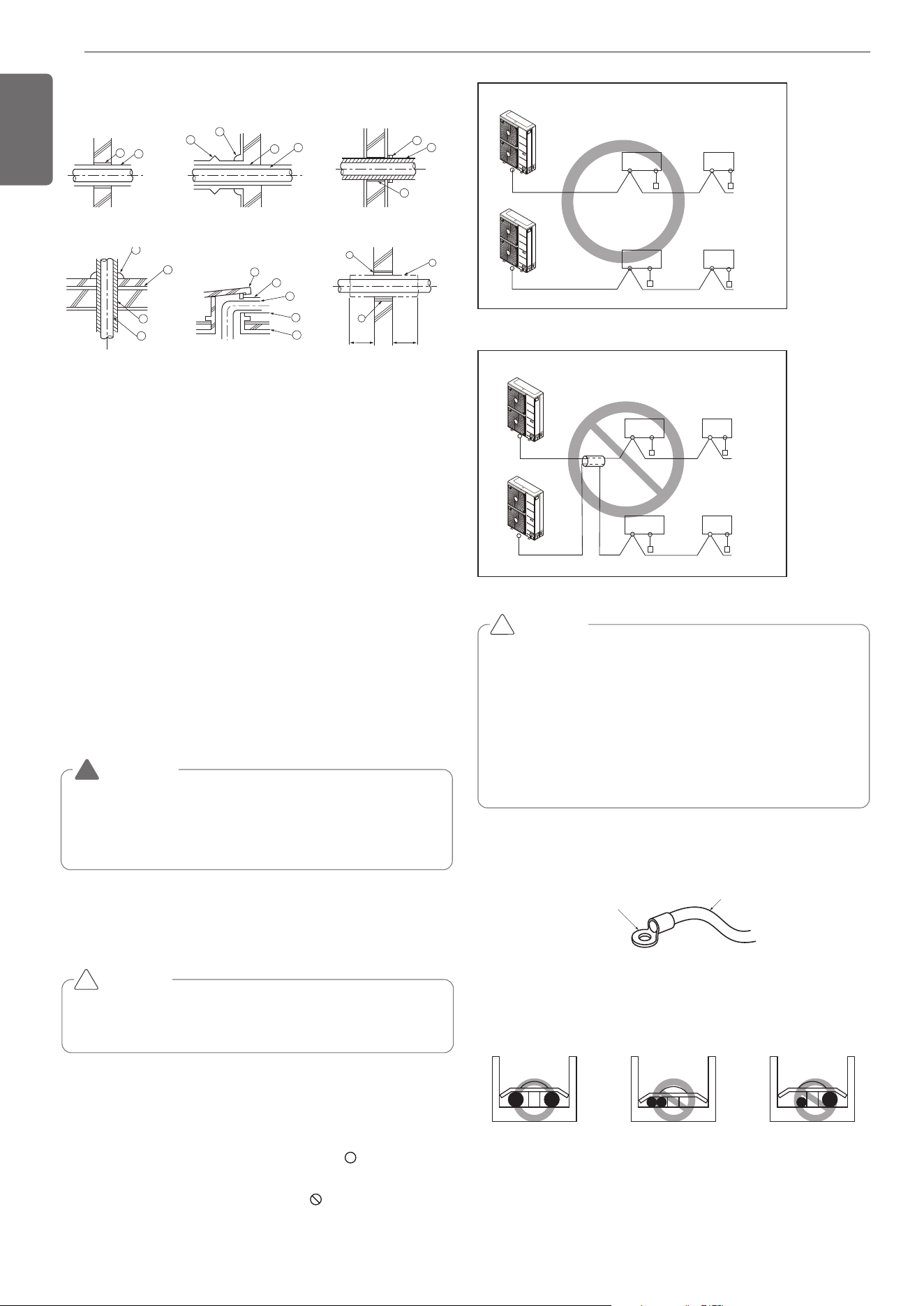
22
ENGLISH
A
B
E
B
I
A
B
D
C
1m1m
D
F
F
G
B
G
D
B
H
I
J
A
Ⓐ Sleeve
Ⓑ Heat insulating material
Ⓒ Lagging
Ⓓ Caulking material
Ⓔ Band
Ⓕ Waterproofing layer
Ⓖ Sleeve with edge
Ⓗ Lagging material
Ⓘ Mortar or other incombustible caulking
Ⓙ Incombustible heat insulation material
When filling a gap with mortar, cover the penetration part with steel plate so
that the insulation material will not be caved in. For this part, use incom-
bustible materials for both insulation and covering. (Vinyl covering should not
be used.)
Inner wall (concealed) Outer wall Outer wall (exposed)
Floor (fireproofing)
Penetrating portion on fire
limit and boundary wall
Roof pipe shaft
-
Install the Outdoor Unit communication cable away from the power
source wiring so that it is not affected by electric noise from the power
source. (Do not run it through the same conduit.)
- Be sure to provide designated grounding work to Outdoor Unit.
- Give some allowance to wiring for electrical part box of Indoor and
Outdoor Units, because the box is sometimes removed at the time of
service work.
- Never connect the main power source to terminal block of communi-
cation cable. If connected, electrical parts will be burnt out.
- Use 2-core shield cable for communication cable.( mark in the fig-
ure below) If communication cable of different systems are wired
with the same multiplecore cable, the resultant poor transmitting and
receiving will cause erroneous operations. ( mark in the figure
below)
- Only the communication cable specified should be connected to the
terminal block for Outdoor Unit communication.
CAUTION
Be sure to correct the outdoor unit to earth. Do not connect ground
wire to any gas pipe, liquid pipe, lightening rod or telephone earth
line. If earth is incomplete, it may cause an electric shock.
!
WARNING
Be sure to have authorized electrical engineers do the electric
work using special circuits in accordance with regulations and this
installation manual.
If power supply circuit has a lack of capacity or electric work defi-
ciency, it may cause an electric shock or fire.
!
Caution
- Follow ordinance of your governmental organization for technical
standard related to electrical equipment, wiring regulations and guid-
ance of each electric power company.
ELECTRICAL WIRING
Penetrations
2-Core Shield Cable
Multi-Core Cable
Remote
control
Remote
control
Remote
control
Remote
control
Indoor
Unit
Outdoor Unit
Outdoor Unit
Indoor
Unit
Indoor
Unit
Indoor
Unit
Outdoor Unit
Outdoor Unit
Remote
control
Remote
control
Indoor
Unit
Indoor
Unit
Remote
control
Remote
control
Indoor
Unit
Indoor
Unit
Precautions when laying power wiring
Use round pressure terminals for connections to the power terminal
block.
Round pressure terminal
Power cable
- For wiring, use the designated power cable and connect firmly, then
secure to prevent outside pressure being exerted on the terminal
block.
- Use an appropriate screwdriver for tightening the terinal screws. A
screwdriver with a small head will strip the head and make proper
tighterning impossible.
- Over-tightening the terminal screws may break them.
CAUTION
• Use the 2-core shield cables for communication cables. Never use
them together with power cables.
• The conductive shielding layer of cable should be grounded to the
metal part of both units.
• Never use multi-core cable
• As this unit is equipped with an inverter, to install a phase leading
capacitor not only will deteriorate power factor improvement effect,
but also may cause capacitor abnormal heating. Therefore, never in-
stall a phase leading capacitor.
• Make sure that the power unbalance ratio is not greater than 2%.
If it is greater the units lifespan will be reduced.
!
When none are available, follow the instructions below.
- Do not connect wiring of different thicknesses to the power terminal
block. (Slack in the power wiring may cause abnormal heat.)
- When connecting cable which is the same thickness, do as shown in
the figure below.
1,MFL69717904,영영 18. 8. 29. 영영 2:49 Page 22
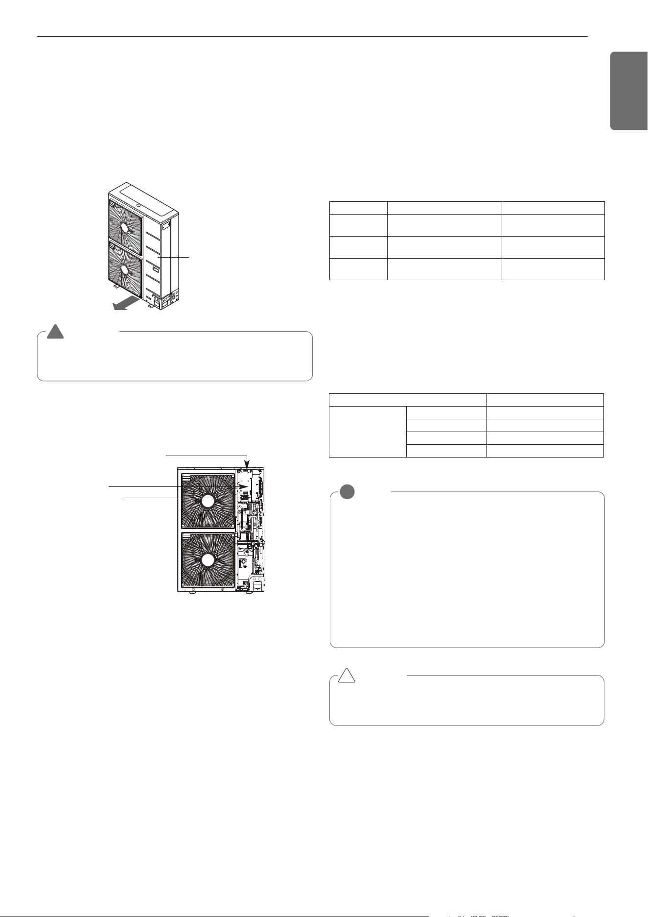
23
ENGLISH
Side panel
WARNING
The temperature sensor for outdoor air should not be exposed to
direct sunlight.
- Provide an appropriate cover to intercept direct sunlight.
!
※Pictures may differ depending on the model.
6 HP
Indoor communication PCB
Main PCB
Terminal block
(Take care of the phase
Sequence of 1-phase
2-wire power system)
(Inside the control box)
NOTE
!
• The figures are based on assumed length of parallel cabling up
to 100m(328ft). For length in excess of 100m(328ft) the figures
will have to be recalculated in direct proportion to the additional
length of cable involved.
• If the power supply waveform continues to exhibit some distor-
tion the recommended spacing in the table should be increased.
- If the cable are laid inside conduits then the following point
must also be taken into account when grouping various cable
together for introduction into the conduits
- Power cable(including power supply to air conditioner) and
communication cables must not be laid inside the same
- In the same way, when grouping the power wires and com-
munication cables should not be bunched together.
CAUTION
If apparatus is not properly earthed then there is always a risk of
electric shocks, the earthing of the apparatus must be carried out by
a qualified person.
!
Communication and Power Cables
Communication cable
- Types : shielding cable
- Cross section : 1.0~1.5mm
2
(1.55x10
-3
~2.32x10
-3
in
2
)
- Maximum allowable temperature: 140°F
- Maximum allowable cable length: under 1,000m(3,281ft)
Remote control cable
- Types : 3-core cable
Central control cable
Separation of communication and power cables
- If communication and power cables are run alongside each other then
there is a strong likelihood of operational faults developing due to in-
terference in the signal wiring caused by electrostatic and electro-
magnetic coupling.
The tables below indicates our recommendation as to appropriate
spacing of communication and power cables where these are to be
run side by side
Product type Cable type Diameter
ACP
2-core cable
(Shielding cable)
1.0~1.5mm
2
(1.55x10
-3
~2.32x10
-3
in
2
)
AC Smart
2-core cable
(Shielding cable)
1.0~1.5mm
2
(1.55x10
-3
~2.32x10
-3
in
2
)
AC Ez
4-core cable
(Shielding cable)
1.0~1.5mm
2
(1.55x10
-3
~2.32x10
-3
in
2
)
Control box and connecting position of wiring
- Remove all of the screws at side panel and remove the panel by
pulling it forward.
- Connect communication cables between outdoor unit and indoor
units through the terminal block.
- When the central control system is connected to the outdoor unit, a
dedicated PCB must be connected between them.
- When connecting communication cable between outdoor unit and in-
door units with shielded cable, connect the shield ground to the earth
screw.
Current capacity of power cable Spacing
100V or more
10A 300mm(11-13/16 inch)
50A 500mm(19-11/16 inch)
100A 1,000mm(39-3/8 inch)
Exceed 100A 1,500mm(59-1/16 inch)
1,MFL69717904,영영 18. 8. 29. 영영 2:49 Page 23
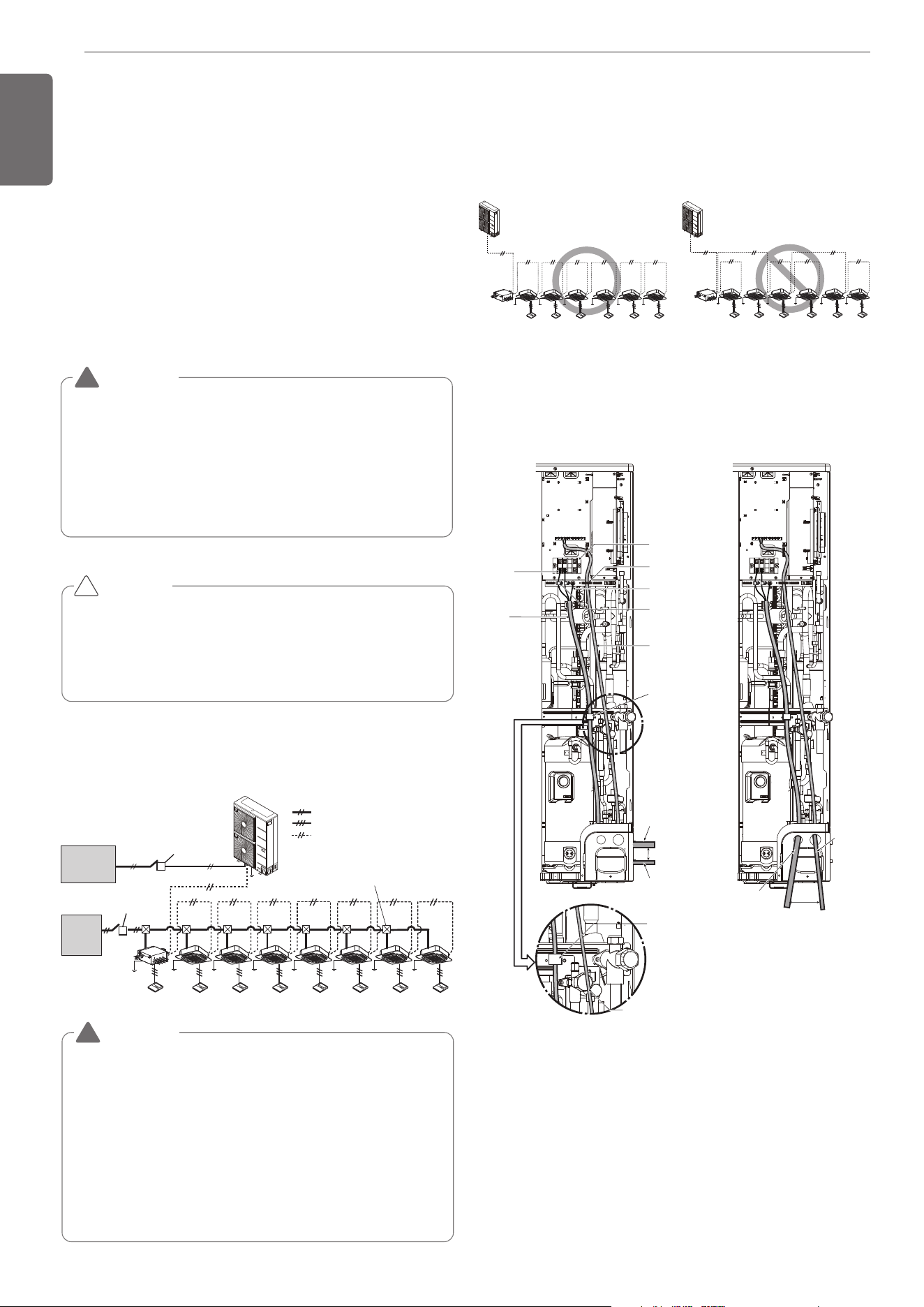
24
ENGLISH
- Use a separate power supply for the Outdoor Unit and Indoor Unit.
- Bear in mind ambient conditions (ambient temperature,direct sun-
light, rain water,etc.) when proceeding with the wiring and connec-
tions.
- The cable size is the minimum value for metal conduit wiring. The
power cord size should be 1 rank thicker taking into account the line
voltage drops. Make sure the power-supply voltage does not drop
more than 10%.
- Specific wiring requirements should adhere to the wiring regulations
of the region.
- Power supply cords of parts of appliances for outdoor use should not
be lighter than polychloroprene sheathed flexible cord.
- Don't install an individual switch or electrical outlet to disconnect
each of indoor unit separately from the power supply.
CAUTION
• Some installation site may require attachment of an earth leakage
breaker. If no earth leakage breaker is installed, it may cause an
electric shock.
• Do not use anything other than breaker and fuse with correct ca-
pacity. Using fuse and wire or copper wire with too large capacity
may cause a malfunction of unit or fire.
!
WARNING
• Follow ordinance of your governmental organization for techni-
cal standard related to electrical equipment, wiring regulations
and guidance of each electric power company.
• Make sure to use specified cables for connections so that no
external force is imparted to terminal connections. If connec-
tions are not fixed firmly, it may cause heating or fire.
• Make sure to use the appropriate type of overcurrent protection
switch. Note that generated overcurrent may include some
amount of direct current.
!
Single outdoor unit
Power supply switch
(Switch fuse : ELCB)
Power supply switch
(Switch fuse)
(Main Switch)
Pull Box(Installer Option)
: Single phase of power supply line[L1(L),L2(N)]
: Communication line (3 line): Wired remote control
: Communication line (2 shield line):
Between Indoor Unit and Outdoor Unit
Power supply
1 Phase
220-240V, 50Hz
220V, 60Hz
Power supply
1 Phase
220-240V, 50Hz
220V, 60Hz
HR unit
HR unit
WARNING
•
Indoor Unit ground wires are required for preventing electrical shock ac-
cident during current leakage, Communication disorder by noise effect
and motor current leakage (without connection to pipe).
• Don't install an individual switch or electrical outlet to disconnect
each of indoor unit separately from the power supply.
• Install the main switch that can interrupt all the power sources in an
integrated manner because this system consists of the equipment
utilizing the multiple power sources.
• If there exists the possibility of reversed phase, lose phase, mo-
mentary blackout or the power goes on and off while the product is
operating, attach a reversed phase protection circuit locally. Run-
ning the product in reversed phase may break the compressor and
other parts.
!
Field Wiring
Wiring of main power supply and equipment
capacity
Example) Connection of transmission wire
[BUS type] [STAR type]
- Connection of communication
cable must be installed like
below figure between indoor
unit to outdoor unit.
- Abnormal operation can be
caused by communication de-
fect, when connection of com-
munication cable is installed like
below figure(STAR type).
HR unit
HR unit
Example) Connection of power and communication cable
6 HP
Right side Front side
ODU-IDU
Communi-
cation cable
Hold Com-
munication
cable
Insulation
sleeves
attachment
Power/
Ground
cable
Power/
Ground cable
View A
Communication
cable
Over
50mm
gap
Fix firmly
not to be
displaced
Hold power
cable
Communication
cable
Main power
Terminal
block
Ground wire
Hold power
cable
Over
50mm gap
Power/
Ground cable
Comm-
unication
cable
A
1,MFL69717904,영영 18. 8. 29. 영영 2:49 Page 24
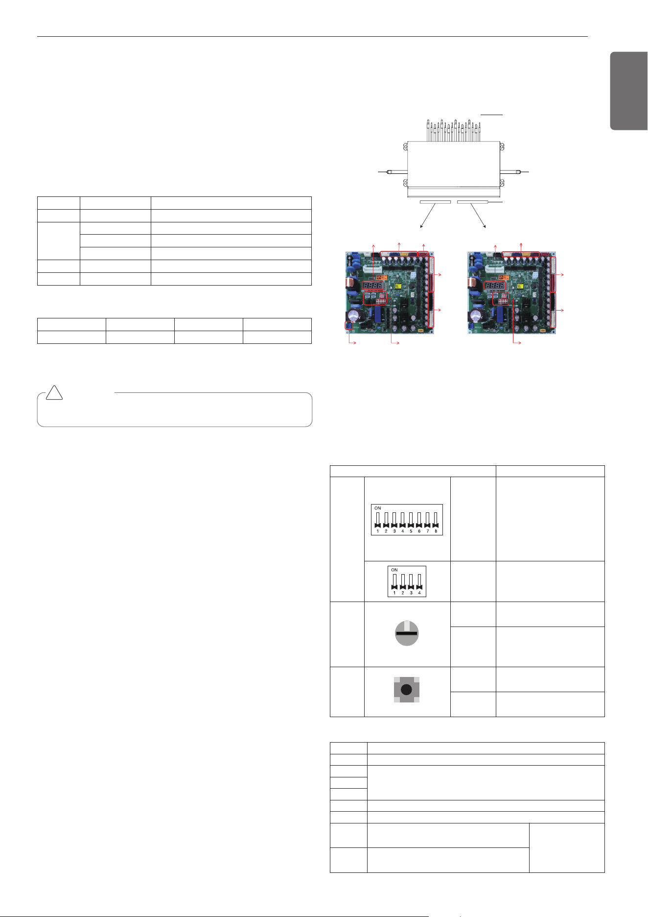
25
ENGLISH
CAUTION
Be sure to turn off outdoor unit power before installation.
!
Checking the setting of outdoor units
Checking according to dip switch setting
- You can check the setting values of the outdoor unit from the 7 seg-
ment LED.
The dip switch setting should be changed when the power is OFF.
Checking the initial display
The number is sequentially appeared at the 7 segment in 5 seconds
after applying the power. This number represents the setting condi-
tion. (For example, represents R410A 10HP)
• Initial display order
• Example) ARUB060GSS4
HR UNIT PCB
For detailed instructions on installing the HR Unit, see the installation
manual included with the HR Unit.
Order No Note
①
4~12 Model capacity
②
1 Cooling only
2 Heat pump
3 Heat Recovery
③
22 220V
④
1 Standard
① ② ③ ④
07 3 22 1
Branch #1~4
Bypass
(from left)
SC EEV
ڸڹںڻڼڽھڿ
Branch #3,4
High/Low
(from top)
Branch #1,2
High/Low
(from top)
Branch #5~8
Bypass
(from left)
Branch #7,8
High/Low
(from top)
Branch #5,6
High/Low
(from top)
7-SEG
Main PCB (2EA, same P/No)
7-SEG
Liquid
Bypass
Valve
- SW02E : Use only SW
No.5
- SW01E : Branch #5~8
(from SW No.1)
- SW01C
- SW01D/SW01C/
SW02B/SW01B/SW02E
- SW01E : Branch #1~4
(from SW No.1)
Branch No.
Main PCB (Master)
Main PCB (Slave)
* Number from left in sequence for less-than-8 branch model.
** PRHR043 / PRHR033 / PRHR023 : Master Only
Main function of SW02E
Setup the switch of HR Unit
ON S/W Selection
No.1 Method for pipe detection of an HR Unit (Auto/Manual)
No.2
No. of connected branchesNo.3
No.4
No.5 Master/Slave (Main PCB) Setting
No.6 EEPROM factory initialization (4,5,6)
No.7
Use only in factory production
(preset to "OFF")
Zoning setting ("ON")
No.8
Use only in factory production
(preset to "OFF")
SW Function
Dip
SW
SW02E
(8pin Dip
SW)
Selection of the method for
pipe detection
Selection of Master/Slave
Main PCB
Setting the Zoning Control
Selection of the No. of con-
nected branches
SW01E
(4pin Dip
SW)
Selection of the valve to ad-
dress
Rotary
SW
0
SW01D
(Left)
Selection of the Valve Group
Control
SW01C
(Right)
Manual addressing of zoning
indoor units
Setting to address HR units
Push
SW
SW02B
(Left)
Increase in the digit of 10
SW01B
(Right)
Increase in the digit of 1
1,MFL69717904,영영 18. 8. 29. 영영 2:50 Page 25
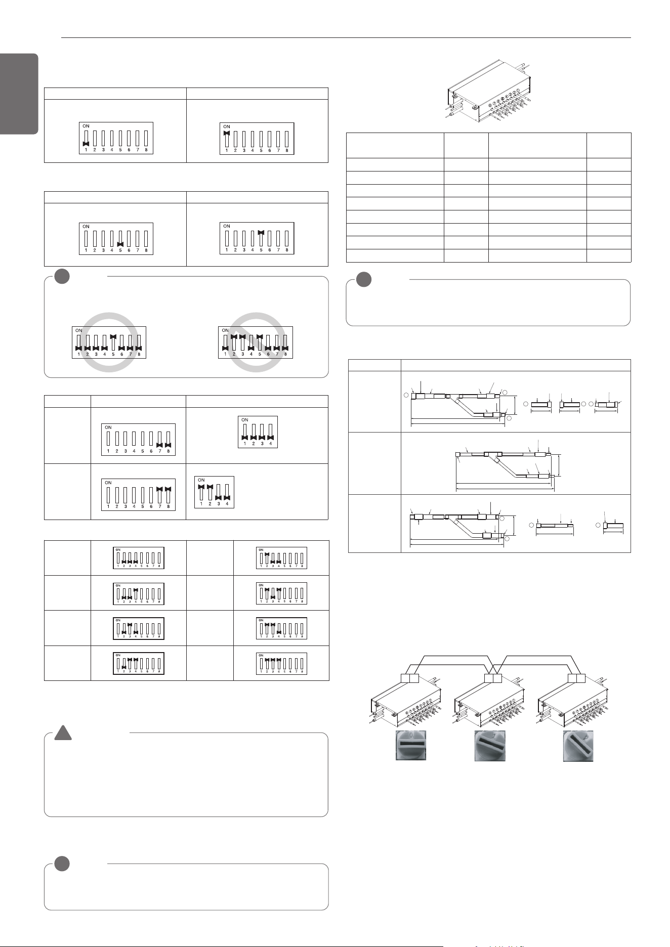
26
ENGLISH
NOTE
!
Use the Valve Group Control when 2 branches are connected with only 1 indoor
unit which has higher capacity than 61 kBTU.
NOTE
!
If the large capacity indoor units are installed, below Y branch pipe should be
used.
Models
ARBLB03321
Low Pressure
Gas Pipe
High Pressure
Gas Pipe
Liquid pipe
413
390
I.D19.05
I.D19.05
I.D19.05
I.D12.7
I.D12.7
70
I.D15.88
I.D15.88
I.D25.4
I.D25.4
O.D25.4
80
110
83
1
2
3
3
O.D19.05
O.D19.05
1
2
I.D22.2
I.D22.2
I.D22.2
I.D28.58
I.D12.7
I.D12.7
I.D12.7
74
332
321
I.D6.35
I.D6.35
I.D9.52(3/8)
I.D9.52
I.D9.52
I.D15.88
I.D12.7
I.D12.7
70
I.D25.4
110
I.D19.05
I.D19.05
2
3 2
3
O.D15.88
444
421
96
I.D15.88
I.D22.2
I.D22.2
I.D22.2
O.D15.88
I.D19.05
I.D9.52
Slave
Slave
1) Selection of the method for pipe detection of an HR unit
(Auto/Manual)
Auto Manual
Master
Master
Switch No.1 Off Switch No.1 On
2) Selection of Master/Slave Main PCB
Master Slave
Switch No.5 Off Switch No.5 On
* Master Only
NOTE
!
Do not turn on any SW02E on Slave Main PCB except No.5.
3) Setting the zoning control
SW02E setting SW01E setting
Normal
control
Master
SW01E
Zoning
control
Master
Master
SW01E
Turn the dip switch of
the zoning branch on.
EX) Branch 1,2 are
zoning control.
4) Selection of the No. of connected branches
1 branch
Connected
5 branch
Connected
2 branches
Connected
6 branch
Connected
3 branches
Connected
7 branch
Connected
4 branches
Connected
8 branch
Connected
* Master Only
* Master Only
* Master Only
h Each model is shipped with the switches No.2, 3, 4 pre-adjusted as
above in the factory.
WARNING
If you want to use a “Model” for “No. of using branch(es)” HR
Unit after closing the “Closing pipe No.”, set the dip switch for
“No. of using branch(es)” HR Unit.
Ex) If you want to use a PRHR083 for 4 branches HR Unit after
closing the 5~8th pipes, set the dip switch for 4 branches HR
Unit.
!
Main function of SW01D
1) Selection of the Valve Group Control
h Y branch pipe
[Unit : mm(inch)]
Valve Group
SW01D
Setting
Valve Group
SW01D
Setting
Not control 0 No. 5,6/7,8 Valve Control 8
No. 1,2 Valve Control 1 No. 1,2/5,6 Valve Control 9
No. 2,3 Valve Control 2 No. 1,2/7,8 Valve Control A
No. 3,4 Valve Control 3 No. 3,4/5,6 Valve Control B
No. 5,6 Valve Control 4 No. 3,4/7,8 Valve Control C
No. 6,7 Valve Control 5
No. 1,2/3,4/5,6 Valve Control
D
No. 7,8 Valve Control 6
No. 1,2/3,4/6,7 Valve Control
E
No. 1,2/3,4 Valve Control 7
No. 1,2/3,4/7,8 Valve Control
F
* Master Only
SW01C (Rotary S/W for addressing HR unit)
Must be set to '0' when installing only one HR unit.
When installing multiple HR units, address the HR units with sequen-
tially increasing numbers starting from '0'.
Maximum 16 HR Units can be installed.
Ex) Installation of 3 HR units
SW01B/SW01C/SW01E/SW02B
(Dip S/W and push S/W for Manual pipe detection)
- Set the address of the valve of the HR unit to the central control ad-
dress of the connected indoor unit.
- SW01E: selection of the valve to address
SW02B: increase in the digit of 10 of valve address
SW01B: increase in the last digit of valve address
SW01C: Manual addressing of zoning indoor units (use for Zoning
setting)
- Prerequisite for Manual pipe detection : central control address of
each indoor unit must be preset differently at its wired remote con-
trol.
AB AB AB
* Master Only
1,MFL69717904,영영 18. 8. 29. 영영 2:50 Page 26
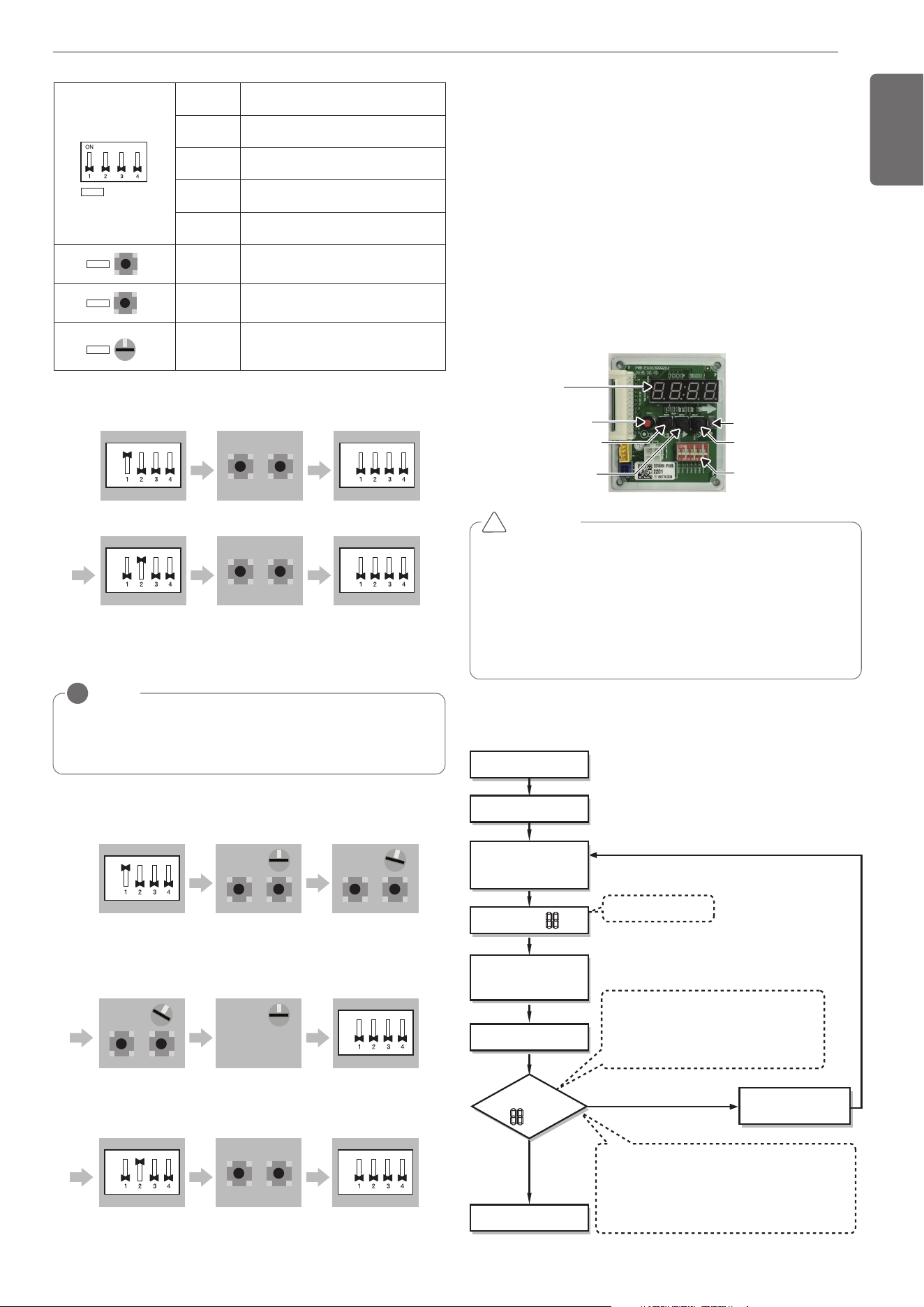
27
ENGLISH
DIP-SWITCH
SW01D(reset)
SW04C(x:cancel)
7-Segment
SW03C(▶:forward)
SW02C(◀:backward)
SW01C(●:confirm)
CAUTION
• In replacement of the indoor unit PCB, always perform Automatic
addressing setting again (At that time, please check about using
Independent power module to any indoor unit.)
• If power supply is not applied to the indoor unit, operation error
occur.
• Automatic Addressing is only possible on the master Unit.
• Automatic Addressing has to be performed after 3 minutes to im-
prove communication.
!
The Procedure of Automatic Addressing
• Automatic addressing setting end
Numbers of indoor unit connection set whose
addressing is completed are indicated for 30seconds
on 7-segment LED after completing setting
Indoor address number is displayed on wired remote control or
indoor unit display window. It is not an error message, will
disappeared when on/off button is pressed on remote control
ex) Display of 01, 02, ..., 15 means connection of 15 indoor units
and Automatic addressing is completed normally.
Automatic addressing start
Waiting 3 minutes
Power On
Press RED Button
for 5 seconds.
(SW01C)
7-segment LED = 88
Don’t press RED Button
(SW01C)
Waiting about 2~7 minutes
7-segment LED
OK
YES
NO Check the connections
of communication cable
= 88
Automatic Addressing
The address of indoor units would be set by Automatic Addressing
- Wait for 3 minutes after supplying power.
(Master and Slave outdoor units, indoor units)
- Press RED button of the outdoor units for 5 seconds. (SW01C)
- A “88” is indicated on 7-segment LED of the outdoor unit PCB.
- For completing addressing, 2~7 minutes are required depending on
numbers of connected indoor units
-
Numbers of connected indoor units whose addressing is completed are
indicated for 30 seconds on 7-segment LED of the outdoor unit PCB
- After completing addressing, address of each indoor unit is indicated
on the wired remote control display window. (CH01, CH02,
CH03, ……, CH06 : Indicated as numbers of connected indoor units)
[Heat Recovery (SERVICE PCB)]
S/W No. Setup
No.1
Manual addressing of valve #1 (Master)
/ #5 (Slave)
No.2
Manual addressing of valve #2 (Master)
/ #6 (Slave)
No.3
Manual addressing of valve #3 (Master)
/ #7 (Slave)
No.4
Manual addressing of valve #4 (Master)
/ #8 (Slave)
SW02B
SW02B
Increase in the digit of 10 of valve ad-
dress
SW01B
SW01B
Increase in the last digit of valve ad-
dress
SW01C
0
SW01C
Manual addressing of zoning indoor
units
* Use for Zoning setting
SW01E
SW01E
SW #1 On : Select Valve #1
Master
ON
OFF
SW02B SW01B
Input the central control
address of Indoor unit
Master
SW01E
SW #1 Off : Finish Valve #1
Master
ON
OFF
SW01E
SW #2 On : Select Valve #6
Slave
ON
OFF
SW02B SW01B
Input the central control
address of Indoor unit
Slave
SW01E
SW #2 Off : Finish Valve #6
Slave
ON
OFF
1) Normal setting (Non-Zoning setting)
ex) Manual pipe detection of Valve #1, 6.
SW01E
SW #1 On : Select Valve #5
Slave
ON
OFF
SW02B SW01B
SW01C
After selecting No.1 zoning
indoor unit, input the central
control address of indoor unit.
Slave
After selecting No.2 zoning
indoor unit, input the central
control address of indoor unit.
Setting SW01C to ‘0’After selecting No.3 zoning
indoor unit, input the central
control address of indoor unit.
SW01E
SW #1 Off : Finish Valve #5
Slave
ON
OFF
SW01E
SW #2 On : Select Valve #6
Slave
ON
OFF
SW02B SW01B
Input the central control
address of Indoor unit
Slave
SW01E
SW #2 Off : Finish Valve #6
Slave
ON
OFF
0
SW02B
SW01C
SW01B
Slave
1
SW01C
Slave
0
SW02B
SW01C
SW01B
Slave
2
NOTE
!
Use the Zoning Control when install two or more indoor units at 1 branch of HR
Unit.
The indoor units controlled by Zoning Control can be selected collectively as the
cooling/heating mode.
2) Zoning setting
ex) Manual pipe detection of Valve #5 with three zoning indoor units,
#6 without zoning unit.
1,MFL69717904,영영 18. 8. 29. 영영 2:50 Page 27
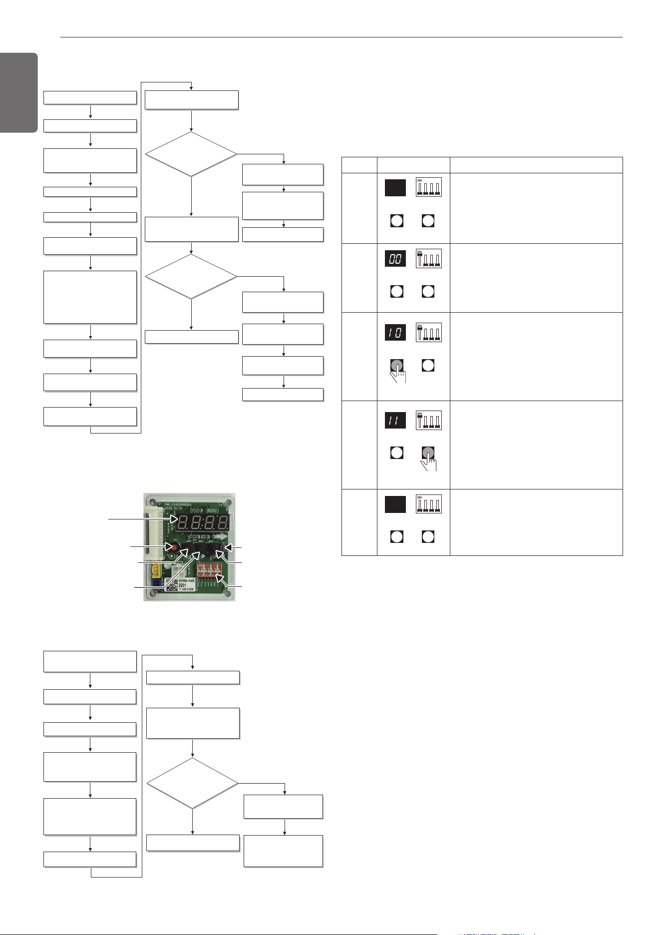
28
ENGLISH
Flow chart of auto addressing for pipe detection
Completion of auto pipe detection
Are the number
of indoor units connected to the
outdoor unit wiring and displayed
one equal?
Reset the power of HR unit PCB
Confirm that the setting of No.2, 3 of
SW02E corresponds with the number of
indoor units.
Master unit PCB DIP switch on : No.5
Select the mode using ‘ȯ’, ‘ȭ’ Button :
“Idu” Push the ‘Ɨ’ button
Select the mode using ‘ȯ’, ‘ȭ’ Button :
“Idu” Push the ‘Ɨ’ button
Select the “Id 6” function using ‘ȯ’, ‘ȭ’
Button :“StA” Push the ‘Ɨ’ button
Select the “Id 5” function using ‘ȯ’, ‘ȭ’
Button :“Ath” or ”Atc” Push the ‘Ɨ’
button.
Outdoor temperature is over 15°C(59°F) :
“Ath” Using
Outdoor temperature is below 15°C(59°F) :
“Atc” Using
88' is displayed on 7-SEG of the outdoor
unit main PCB
Outdoor unit is operated for 5~60 minutes.
The number of indoor units detected is
displayed for 30 seconds on the outdoor
unit PCB after outdoor unit stopped
Display error on outdoor unit PCB
Display error on HR unit PCB
Outdoor unit PCB : HR
⇒
HR unit
number
⇒
Valve number
HR unit : '200'
Check the HR unit and indoor unit
Pipe detection error occur after 30
seconds.
Check the installation of pipe of
outdoor, indoor, HR unit
Incompletion of auto pipe detection
Retry auto pipe detection after
checking trouble
Is the pipe
setting condition
satisfied during the operation of
indoor unit?
Confirmation of indoor unit address setting
Turn No.1 of SW02E of HR unit PCB off.
NO
NO
YES
YES
※It is possible to be generated mode changing noise of heating and
cooling which is normal. There is no mode changing noise at normal
operation.
DIP-SWITCH
SW01D(reset)
SW04C(x:cancel)
7-Segment
SW03C(▶:forward)
SW02C(◀:backward)
SW01C(●:confirm)
Flow chart of manual addressing for pipe detection
Completion of manual pipe detection
Reset the power of HR unit PCB.
Enter the central control address into
each indoor unit using its wired remote
control.
On the HR unit PCB, manually set address
of each valve of the HR unit to the central
control address of the indoor unit
connected to the valve.
Reset the power of outdoor unit PCB.
Wait for about 5 minutes.
The number of the indoor units installed is
displayed.
Ex)HR
⇒
The number of the indoor
Check the central control address of
indoor and HR unit.
Make sure that reset the outdoor
unit power when changing the
central control unit
Are the number
of indoor units connected to the
outdoor unit and displayed one
equal?
Execute in case of Auto pipe detection
failure
Turn No.1 of SW02E of HR unit PCB on.
NO
YES
Example of manual valve addressing (Non-
Zoning setting)
(In case that an indoor unit of central control address "11" is connected
to a valve #1 of an HR unit)
- Prerequisite for manual valve addressing: central control address of
each indoor unit must be preset differently at its wired remote con-
trol.
- Above setup must be done for all HR unit valves.
- The valve that is not connected with any indoor unit should be ad-
dressed with any other number than used address numbers of the
valves connected with indoor units.
(The valves does not work if the address numbers are same.)
Example of manual valve addressing (Zoning
setting)
(In case that an indoor unit of central control address “11”, “12” is
connected to a valve #1 of an HR unit)
Zoning control is connecting 2 or more indoor units at one pipe of HR
unit. In case of Zoning control, in order to set controls with multiple in-
door units connection uses the rotary switch. Namely, only the rotary
switch changes from same valve set condition and set indoor units
connection.
1) On dip switch of the corresponding valves and sets the rotary
switch at 0.
2) Setting the number with tact switch.
3) In case of addition of indoor units to same port, increases 1 with the
rotary switch and sets number with tact switch.
4) In case of checking the number which the corresponding valve is
stored, turn on dip switch and set the number of rotary switch.
5) Indoor units set available 8 per a port(rotary switch 0~7), in case of
setting above of 8 with rotary switch, it will display error.
6) Setting the rotary switch on original condition(HR unit number set
conditions) after all finishing a piping setting.
No.Display and setup Setup and Contents
1
7-SEG SW01E
SW02B SW01B
- Operation: None
- Display: None
2
7-SEG SW01E
SW02B SW01B
- Operation: Turn dip S/W No.1 on to ad-
dress valve #1
- Display: Existing value saved in EEP-
ROM is displayed in
7-SEG.
3
7-SEG SW01E
SW02B SW01B
- Operation: Set the digit of 10 to the
number in Group High data of the wired
remote control connected to the corre-
sponding indoor unit to the valve #1 by
pressing left tack S/W.
- Display: Digit increasing with the times
of pressing tack S/W is displayed in left
7-SEG
4
7-SEG SW01E
SW02B SW01B
- Operation: Set the digit of 1 to the num-
ber in Group Low data of the wired re-
mote control connected to the
corresponding indoor unit to the valve
#1 by pressing right tack S/W.
- Display: Digit increasing with the times
of pressing tack S/W is displayed in right
7-SEG
5
7-SEG SW01E
SW02B SW01B
- Operation: Turn dip S/W No.1 off to save
the address of
valve #1
- Display: "11" displayed in 7-SEG disap-
pears
1,MFL69717904,영영 18. 8. 29. 영영 2:50 Page 28
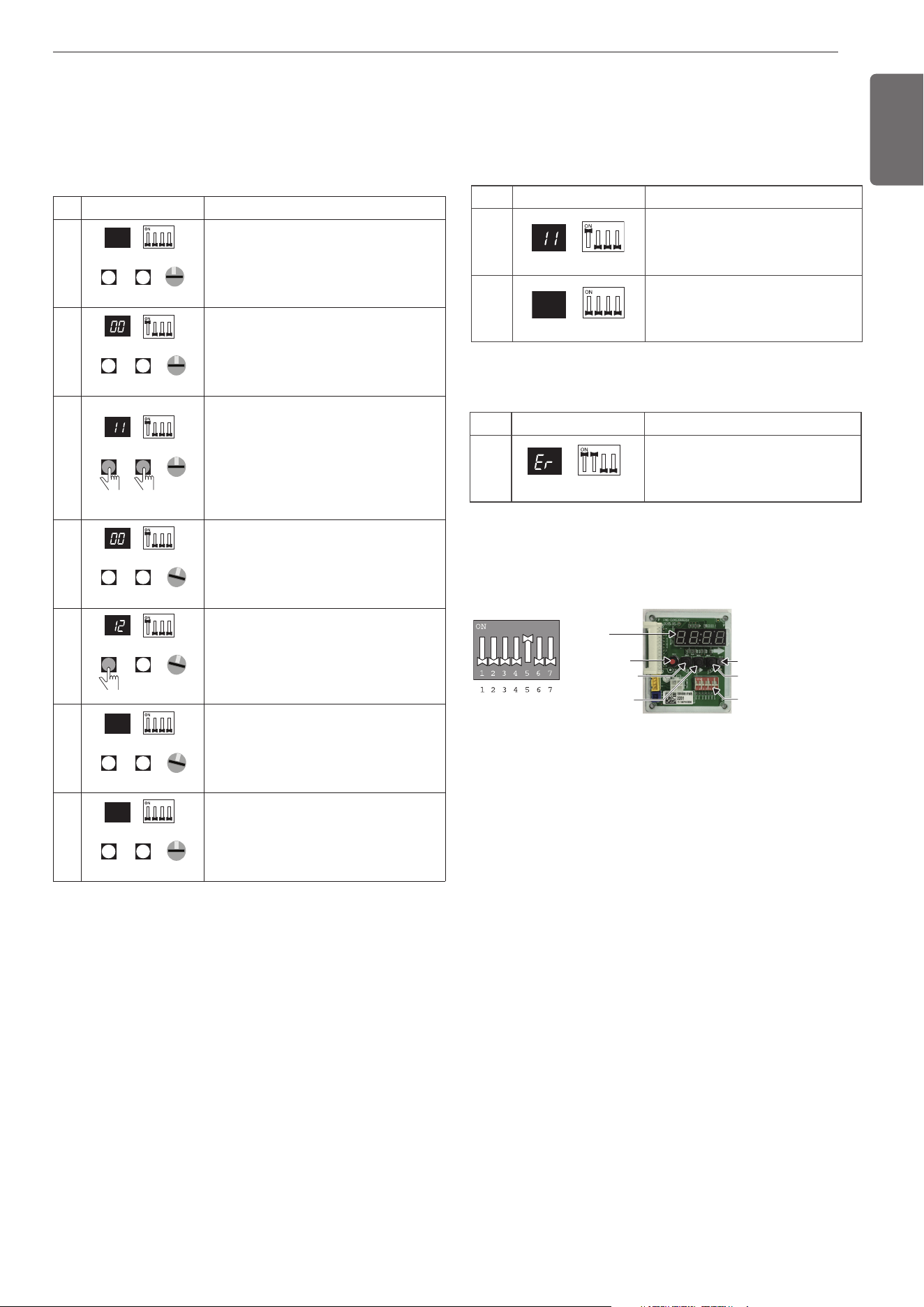
29
ENGLISH
Identification of Manual Valve ID (Address)
No. Display and setup Setup and Contents
1
7-SEG SW01E
- Operation: more than 2 dip switches
turned on.
- Display: "Er" is displayed in 7-SEG
7) The rotary switch set value of above number of indoor units which is
connected with FF and prevents a malfunction.
(Example: The case where 3 indoor units is connected in piping 1,
sets from rotary switch 0,1,2 and 3,4,5,6,7 with FF set)
- Prerequisite for manual valve addressing: central control address of
each indoor unit must be preset differently at its wired remote con-
trol.
- Above setup must be done for all HR unit valves.
- The valve that is not connected with any indoor unit should be ad-
dressed with any other number than used address numbers of the
valves connected with indoor units.(The valves does not work if the
address numbers are same.)
No.Display and setup Setup and Contents
1
7-SEG SW01E
SW02B SW01B
0
SW01C
- Operation: None
- Display: None
2
7-SEG SW01E
SW02B SW01B
SW01C
0
- Operation : Turn dip S/W No.1 on to ad-
dress valve #1
- Display : Existing value saved in EEP-
ROM is displayed in 7-SEG.
3
7-SEG SW01E
SW02B SW01B
SW01C
0
- Operation : Set the digit of 10(1) to the
number in Group High data of the wired
remote control connected to the corre-
sponding indoor unit to the valve #1 by
pressing left tack S/W.
- Display : Digit increasing with the times
of pressing tack S/W is displayed in left
7-SEG.
4
1
7-SEG SW01E
SW02B SW01B
SW01C
- Operation : SW01C : 1
- Display : Display former value.
5
7-SEG SW01E
SW02B SW01B
SW01C
1
- Operation : Setting No. using SW02B
and SW01B, SW01C : 1
- Display : Display setting value.
6
7-SEG SW01E
SW02B SW01B
SW01C
1
- Operation : Turn dip S/W No.1 off to save
the address of valve #1
- Display : "11" displayed in 7-SEG disap-
pears.
7
7-SEG SW01E
SW02B SW01B
SW01C
0
- Operation : Return valve of addressing
HR unit.
- Display : None
Setting the function
Select the mode/function/option/value using ‘▶’, ‘◀’ Button and con-
firm that using the ‘●’ button after dip switch No.5 is turned on.
DIP-SWITCH
SW01D(reset)
SW04C(x:cancel)
7-Segment
SW03C(▶:forward)
SW02C(◀:backward)
SW01C(●:confirm)
Method of checking the pipe detection result
at HR unit
In case that an indoor unit of central control address "11" is connected to a
valve #1 of an HR unit
No. Display and setup Setup and Contents
1
7-SEG SW01E
- Operation: Turn dip S/W No.1 on.
- Display: "11" is displayed in 7-SEG
2
7-SEG SW01E
- Operation: Turn dip S/W No.1 off.
- 7-SEG disappeared
1,MFL69717904,영영 18. 8. 29. 영영 2:50 Page 29
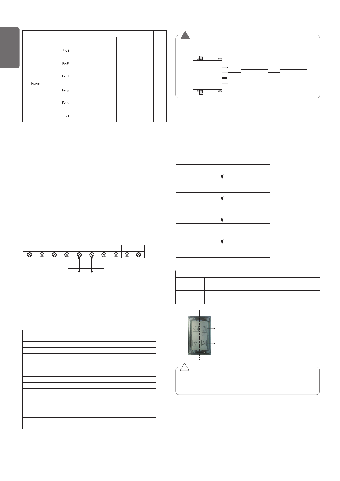
30
ENGLISH
Example) Group number setting
1
st
number indicate the group number
2nd number point out indoor unit number
ODU.B ODU.A IDU.B IDU.A CEN.B CEN.A DRY1 DRY2 GND 12V
B(D) A(C)
1 F
Group Indoor unit
Group recognizing the central controller
No.0 group (00~0F)
No.1 group (10~1F)
No.2 group (20~2F)
No.3 group (30~3F)
No.4 group (40~4F)
No.5 group (50~5F)
No.6 group (60~6F)
No.7 group (70~7F)
No.8 group (80~8F)
No.9 group (90~9F)
No. A group (A0~AF)
No. B group (B0~BF)
No. C group (C0~CF)
No. D group (D0~DF)
No. E group (E0~EF)
No. F group (F0~FF)
Mode Function Option Value Action
Remarks
Content
Display1
Content
Display2
Content Display3
Content Display4
Implement Display5
Cool & Heat
Selector
oFF
op1~
op2
Selected
the option
- -
Change
the set
value
Blank
Save in
EEPROM
Static pres-
sure com-
pensation
oFF
op1~
op3
Selected
the option
- -
Change
the set
value
Blank
Save in
EEPROM
Night low
noise
oFF
op1~o
p12
Selected
the option
- -
Change
the set
value
Blank
Save in
EEPROM
ODU
address
-
-
0~255
set
the
value
Change
the set
value
Blank
Save in
EEPROM
Snow re-
moval &
rapid defrost
oFF
op1~
op3
Selected
the option
- -
Change
the set
value
Blank
Save in
EEPROM
Target
pressure
adjusting
oFF
op1~
op3
Selected
the option
- -
Change
the set
value
Blank
Save in
EEPROM
Valve (04)
EX)
Valve (03)
Valve (02)
Valve (01)
Indoor unit (04)
Indoor unit (03)
Indoor unit (02)
Indoor unit (01)
Central control address
HR unit
WARNING
• Valve address and central control address of its corresponding indoor
unit should be set identical in manual addressing.
!
TEST RUN
Cool & Heat selector
Mode setting method
Service PCB DIP switch on : No.5
Select the mode using ‘▶’, ‘◀’ Button :
“Func” Push the ‘●’ button
Select the Function using ‘▶’, ‘◀’ Button :
“Fn1” Push the ‘●’ button
Select the Option using ‘▶’, ‘◀’ Button :
“oFF”,“op1”,“op2” Push the ‘●’ button
Cool & Heat Selection mode is set
Function setting
Switch control Function
Switch(TOP) Switch(Bottom)
oFF op1(mode) op2(mode)
Right Left Not operate Cooling Cooling
Right Right Not operate Heating Heating
Left - Not operate Fan mode Off
CAUTION
• Ask an authorized technician to setting a function.
• If do not use a function, set an off-mode.
• If use a function, first install a Cool & Heat selector.
!
Switch (TOP)
Switch (Bottom)
Left side
Right side
* Functions save in EEPROM will be kept continuously, though the
system power was reset.
* Dip switch 3 can be OFF except when installing the only 4 series in-
door units (named ARNU***4).
Group Number setting
Group Number setting for Indoor Units
- Confirm the power of whole system(Indoor Unit, Outdoor Unit) is
OFF, otherwise turn off.
- The communication cables connected to CEN.A and CEN.B terminal
should be connected to central control of Outdoor Unit with care for
their polarity (A-A, B-B ).
- Turn the whole system on.
- Set the group and Indoor Unit number with a wired remote control.
- To control several sets of Indoor Units into a group, set the group ID
from 0 to F for this purpose.
Outdoor Units (Main PCB)
Installation
1,MFL69717904,영영 18. 8. 29. 영영 2:50 Page 30
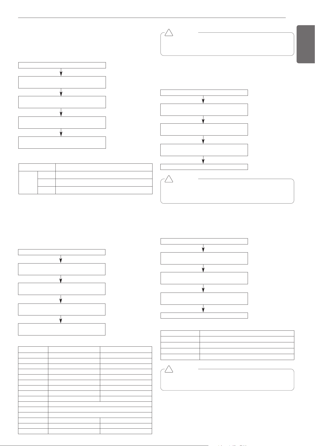
31
ENGLISH
Service PCB DIP switch on : No.5
Select the mode using ‘▶’, ‘◀’ Button :
“Func” Push the ‘●’ button
Select the Function using ‘▶’, ‘◀’ Button :
“Fn6” Push the ‘●’ button
Select the Option using ‘▶’, ‘◀’ Button :
“oFF”,“op1” ~ “op3” Push the ‘●’ button
Mode is set
CAUTION
• Ask an authorised technician to set up this function
• If you do not want to use this function, simply set off-mode
!
Mode setting
setting Mode
oFF Not setting
op1 Snow removal mode
op2 Rapid defrost mode
op3 Snow removal mode. + Rapid defrost mode.
Snow removal & rapid defrost
Mode setting method
Setting the ODU address
Mode setting method
CAUTION
• Request installer to set the function during installation.
• If ODU RPM changes, cooling capacity may go down.
!
Service PCB DIP switch on : No.5
Select the mode using ‘▶’, ‘◀’ Button :
“Func” Push the ‘●’ button
Select the Function using ‘▶’, ‘◀’ Button :
“Fn3” Push the ‘●’ button
Select the Option using ‘▶’, ‘◀’ Button :
“op1~op15” Push the ‘●’ button
Start the Night low noise function :
Save the selected option value in EEPROM
Time Settings
Step Judgement Time(Hr) Operation Time(Hr)
op1 8 9
op2 6.5 10.5
op3 5 12
op4 8 9
op5 6.5 10.5
op6 5 12
op7 8 9
op8 6.5 10.5
op9 5 12
op10 continuous operation
op11 continuous operation
op12 continuous operation
op13 6.5 10.5
op14 6.5 10.5
op15 6.5 10.5
Service PCB DIP switch on : No.5
Select the mode using ‘▶’, ‘◀’ Button :
“Func” Push the ‘●’ button
Select the Function using ‘▶’, ‘◀’ Button :
“Fn5” Push the ‘●’ button
Select the Option using ‘▶’, ‘◀’ Button :
“0” ~ “255” Push the ‘●’ button
ODU address is set
CAUTION
• Ask an authorized technician to setting a function.
• If use a function, first install a Central controller.
!
Night Low Noise Function
In cooling mode, this function makes the ODU fan operate at low RPM
to reduce the fan noise of ODU at night which has low cooling load.
Night low noise function setting method
FAN Maximum RPM of each step
Model ARUB060GSS4
Max.RPM
OP1 850
OP2 850
OP3 1000
Service PCB DIP switch on : No.5
Select the mode using ‘▶’, ‘◀’ Button :
“Func” Push the ‘●’ button
Select the Function using ‘▶’, ‘◀’ Button :
“Fn2” Push the ‘●’ button
Select the Option using ‘▶’, ‘◀’ Button :
“op1~op3” Push the ‘●’ button
Start the Static pressure compensation mode :
Save the selected option value in EEPROM
Static pressure compensation mode
This function secures the air flow rate of ODU, in case static pressure
has been applied like using duct at fan discharge of ODU.
Static pressure compensation mode setting method
1,MFL69717904,영영 18. 8. 29. 영영 2:50 Page 31
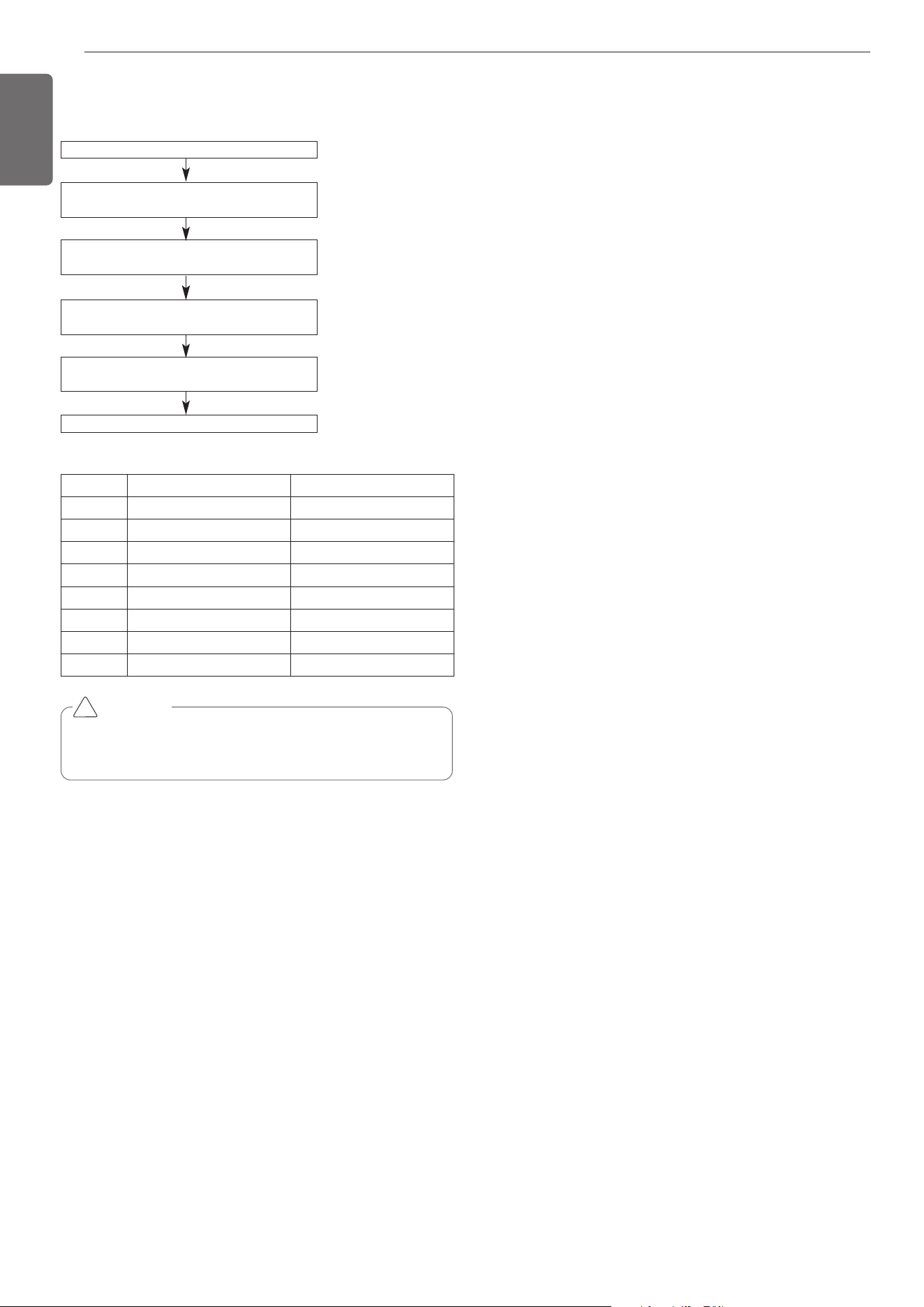
32
ENGLISH
Service unit PCB DIP switch on : No.5
Select the mode using ‘▶’, ‘◀’ Button :
“Func” Push the ‘●’ button
Select the Function using ‘▶’, ‘◀’ Button :
“Fn8” Push the ‘●’ button
Select the Option using ‘▶’, ‘◀’ Button :
“oFF “, “ op1 “ ~ “op7 “ Push the ‘●’ button
Target pressure is set
Select the Option using ‘▶’, ‘◀’ Button :
“HEAT” , “COOL” Push the ‘●’ button
CAUTION
• Ask an authorized technician to setting a function.
• If do not use a function, set an off-mode.
• Change a power consumption or capacity.
!
Setting
Target pressure adjusting
Mode setting method
Mode Low Pressure (kpa) High pressure (kpa)
oFF 804 2990
op1 699 3121
op2 739 2827
op3 843 2696
op4 908 2565
op5 961 2435
op6 1026 2304
op7 804 2990
1,MFL69717904,영영 18. 8. 29. 영영 2:50 Page 32
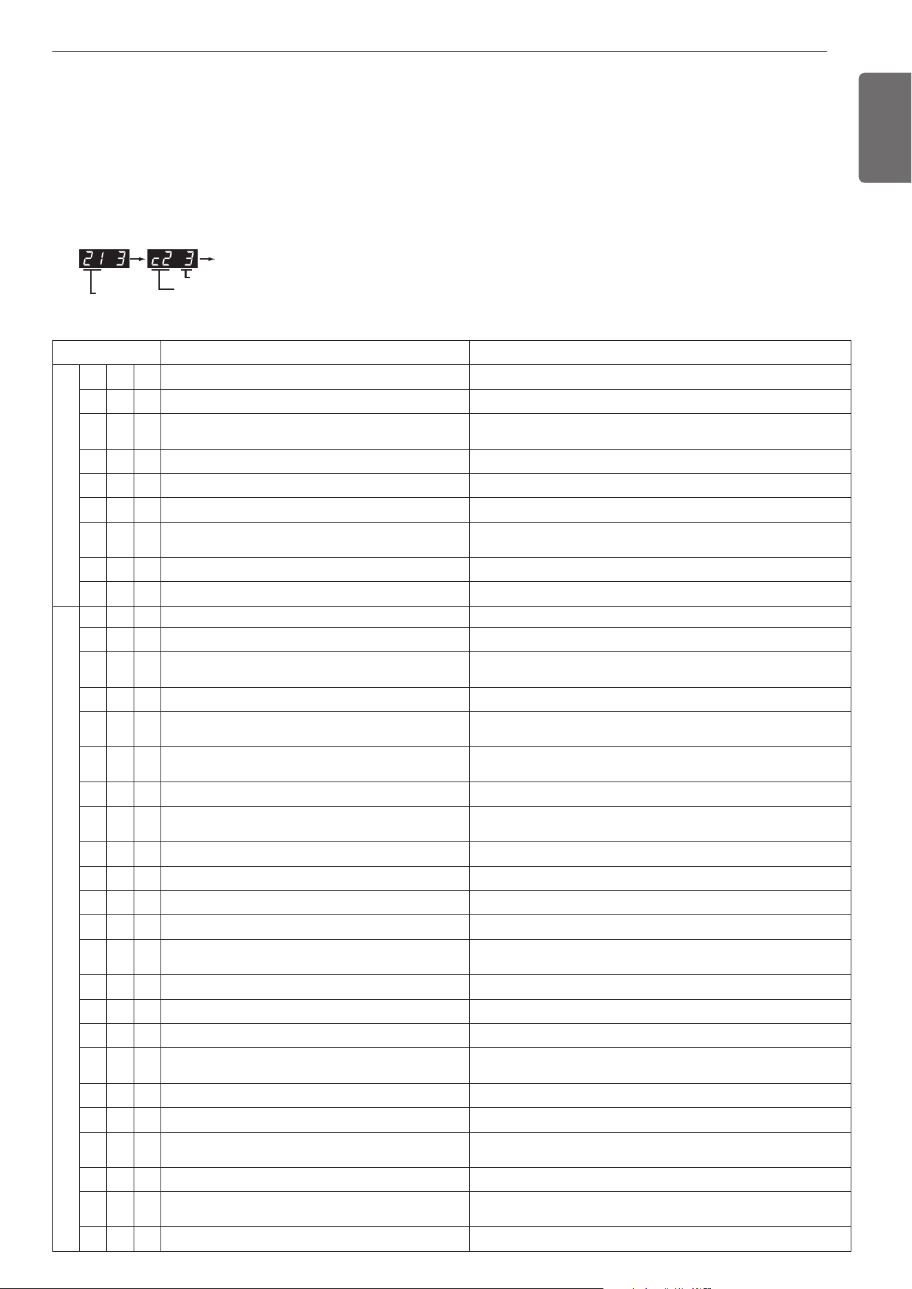
33
ENGLISH
Error No. of Compressor
Error No.
Error No. of Unit
Repeat
* Refer to the Indoor manual for some Indoor Error code.
Self-Diagnosis Function
Error Indicator
- This function indicates types of failure in self-diagnosis and occurrence of failure for air condition.
- Error mark is displayed on display window of indoor units and wired remote controller, and 7-segment LED of outdoor unit control board as
shown in the table.
- If more than two troubles occur simultaneously, lower number of error code is first displayed.
- After error occurrence, if error is released, error LED is also released simultaneously.
Error Display
1st,2nd,3rd LED of 7-segment indicates error number, 4th LED indicates unit number.
Ex)
Display Title Cause of Error
0 1 - Air temperature sensor of indoor unit Air temperature sensor of indoor unit is open or short
0 2 - Inlet pipe temperature sensor of indoor unit Inlet pipe temperature sensor of indoor unit is open or short
0 3 -
Communication error : wired remote controller ÷ in-
door unit
Failing to receive wired remote controller signal in indoor unit PCB
0 4 - Drain pump Malfunction of drain pump
0 5 -
Communication error : outdoor unit ÷ indoor unit
Failing to receive outdoor unit signal in indoor unit PCB
0 6 - Outlet pipe temperature sensor of indoor unit Outlet pipe temperature sensor of indoor unit is open or short
0 9 - Indoor EEPROM Error
In case when the serial number marked on EEPROM of Indoor unit is 0
or FFFFFF
1 0 - Poor fan motor operation Disconnecting the fan motor connector/Failure of indoor fan motor lock
1 1 -
Communication error, Indoor unit ↔ Outdoor unit
Failing to receive signal in indoor unit
2 1 * Outdoor Unit Inverter Compressor IPM Fault Outdoor Unit Inverter Compressor Drive IPM Fault
2 2 * Inverter Board Input Over Current(RMS) of Outdoor Unit Outdoor Unit Inverter Board Input Current excess (RMS)
2 3 * Outdoor Unit Inverter Compressor DC link Low Voltage
DC charging is not performed at Outdoor Unit after starting relay turn
on.
2 4 * Outdoor Unit High Pressure Switch System is turned off by Outdoor Unit high pressure switch.
2 5 * Outdoor Unit Input Voltage High/ Low Voltage
Outdoor Unit input voltage is over 289V or below 73V(ARUB***BTE4)
Outdoor Unit input voltage is over 506V or below 414V(ARUB***DTE4)
2 6 * Outdoor Unit Inverter Compressor Start Failure
The First Start Failure by Outdoor Unit Inverter Compressor Abnor-
mality
2 9 *
Outdoor Unit Inverter Compressor Over Current Outdoor Unit Inverter Compressor Fault or Drive Fault
3 2 *
Outdoor Unit Inverter Compressor1 High Discharge Tem-
perature
Outdoor Unit Inverter Compressor1 High Discharge Temperature
3 4 *
High Pressure of Outdoor Unit High Pressure of Outdoor Unit
3 5 *
Low Pressure of Outdoor Unit Low Pressure of Outdoor Unit
36*
Outdoor Unit Low Compression Ratio Limited Outdoor Unit Low Compression Ratio Limited
40*
Outdoor Unit Inverter Compressor CT Sensor Fault Outdoor Unit Inverter Compressor CT Sensor open or short
41*
Outdoor Unit Inverter Compressor1 Discharge Tempera-
ture Sensor Fault
Outdoor Unit Inverter Compressor Discharge Temperature Sensor open
or short
42*
Outdoor Unit Low Pressure Sensor Fault Outdoor Unit Low Pressure Sensor open or short
43*
Outdoor Unit High Pressure Sensor Fault Outdoor Unit High Pressure Sensor open or short
44*
Outdoor Unit Air Temperature Sensor Fault Outdoor Unit Air Temperature Sensor open or short
45*
Outdoor Unit Heat Exchanger Temperature Sensor (Front
side) Fault
Outdoor Unit Heat Exchanger Temperature Sensor(Front side) open or
short
46*
Outdoor Unit Suction Temperature Sensor Fault Outdoor Unit Suction Temperature Sensor open or short
50*
Omitting connection of R, S, T power of Outdoor Unit Omitting connection of outdoor unit
51*
Excessive capacity of indoor units
Excessive connection of indoor units compared to capacity of Outdoor
Unit
52*
Communication error : inverter PCB ’ Main PCB
Failing to receive inverter signal at main PCB of Outdoor Unit
53*
Communication error : indoor unit ’ Main PCB of Out-
door Unit
Failing to receive indoor unit signal at main PCB of Outdoor Unit .
57 -
Communication error : Main PCB ’ inverter PCB
Failing to receive signal main PCB at inverter PCB of Outdoor Unit
Outdoor unit related error
Indoor unit related error
1,MFL69717904,영영 18. 8. 29. 영영 2:50 Page 33
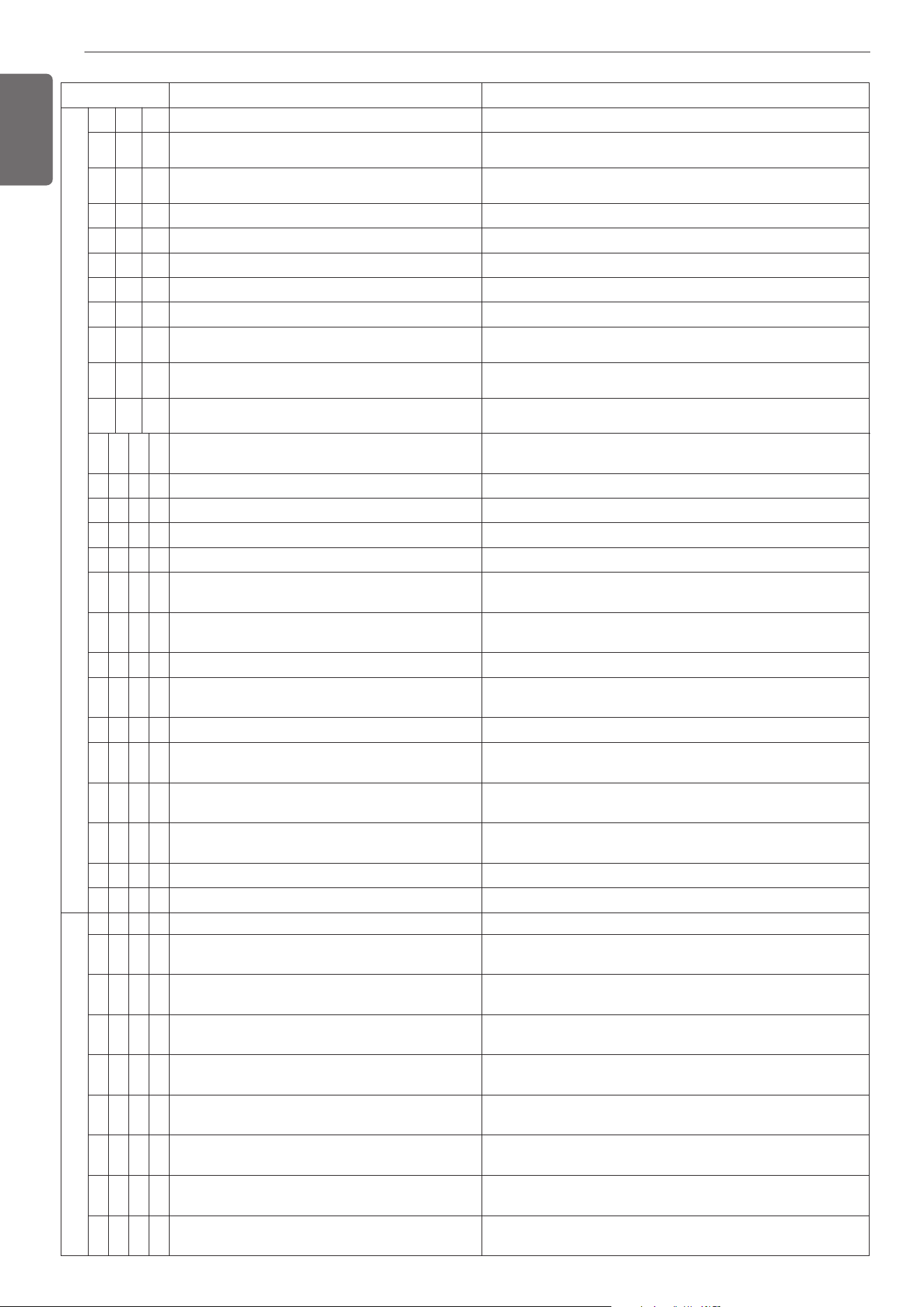
34
ENGLISH
Display Title Cause of Error
6 0 *
Inverter PCB EEPROM Error of Outdoor Unit Access Error of Inverter PCB of Outdoor Unit
6 2 *
Outdoor Unit Inverter Heatsink High Temperature
System is turned off by Outdoor Unit Inverter Heatsink High Tempera-
ture
6 5 *
Outdoor Unit Inverter Heatsink Temperature Sensor
Fault
Outdoor Unit Inverter Heatsink Temperature Sensor open or short
6 7 *
Outdoor Unit Fan Lock Restriction of Outdoor Unit
7 1 *
Converter CT Sensor Error of Outdoor Unit Converter CT Sensor open or short of Outdoor Unit
7 5 *
Outdoor Unit Fan CT Sensor Error Outdoor Unit Fan CT Sensor open or short
7 6 *
Outdoor Unit Fan DC Link High Voltage Error Outdoor Unit Fan DC Link High Voltage Error
7 7 *
Outdoor Unit Fan Over Current Error Outdoor Unit Fan Current is over 5A
7 9 *
Outdoor Unit Fan Start Failure Error
Outdoor Unit Fan First Position Sensing
Failure
8 6 *
Outdoor Unit Main PCB EEPROM Error
Communication Fail Between Outdoor Unit Main MICOM and EEP-
ROM or omitting EEPROM
8 7 *
Outdoor Unit Fan PCB EEPROM Error
Communication Fail Between Outdoor Unit Fan MICOM and EEP-
ROM or omitting EEPROM
1 0 4 *
Communication Error Between Outdoor Unit and Other
Outdoor Unit
Failing to receive Slave Unit signal at main PCB of Outdoor Unit
1
0
5
*
Outdoor Unit Fan PCB Communication Error Failing to receive fan signal at main PCB of unit.
1 0
6
*
Outdoor Unit FAN IPM Fault Error Instant Over Current at Outdoor Unit Fan IPM
1
0
7
*
Outdoor Unit Fan DC Link Low Voltage Error Outdoor Unit Fan DC Link Input Voltage is under 380V
113
*
Outdoor Unit Liquid pipe Temperature Sensor Error Liquid pipe temperature sensor of Outdoor Unit is open or short
114
*
Outdoor Unit Subcooling Inlet Temperature Sensor
Error
Outdoor Unit Subcooling Inlet Temperature Sensor Error
115
*
Outdoor Unit Subcooling Outlet Temperature Sensor
Error
Outdoor Unit Subcooling Outlet Temperature Sensor Error
116
*
Outdoor Unit Oil Level Sensor Error Oil Level Sensor of Outdoor Unit is open or short
145*
outdoor unit Main Board - External Board communica-
tion Error
outdoor unit Main Board - External Board communication Error
1
5
1
*
Failure of operation mode conversion at Outdoor Unit Failure of operation mode conversion at Outdoor Unit
15
3
*
Outdoor Unit Heat Exchanger Temperature Sensor
(upper part) Fault
Outdoor Unit Heat Exchanger Temperature Sensor (upper part) Fault
1
5
4
*
Outdoor Unit Heat Exchanger Temperature Sensor
(lower part) Fault
Outdoor Unit Heat Exchanger Temperature Sensor(lower part) open
or short
182
*
outdoor unit External Board Main-Sub Micom communi-
cation Error
Outdoor Unit Main Board Main-Sub Micom communication failed
193
*
Outdoor Unit Fan Heatsink High Temperature System is turned off by Outdoor Unit Fan Heatsink High Temperature
194
*
Outdoor Unit Fan Heatsink Temperature Sensor Fault Outdoor Unit Fan Heatsink Temperature Sensor open or short
2001
Searching pipe Error Failure of automatic addressing of valves
201
C +
#HR
HR unit1 Liqiud sensor error Liquid pipe sensor of HR unit open or short
202
C +
#HR
HR unit1 Sub Cooling Pipe In sensor error Sub Cooling Pipe In sensor of HR unit open or short
203
C +
#HR
HR unit1 Sub Cooling Pipe Out sensor error Sub Cooling Pipe Out sensor of HR unit. open or short
204
C +
#HR
Communication error Failing to receive HR unit signal at outdoor unit
205
C +
#HR
Communication error between HR unit and the
upgraded 485 modem.
4 series upgraded 485 communication error between HR unit and
HR unit modem
206
C +
#HR
Duplicate address error of HR unit
When the HR unit address is set duplicated at the 4 series
upgraded 485 communication
207
C +
#HR
Communication error between Master and Slave Main
PCB of HR Unit
When fail to communication between Master and Slave Main PCB
of HR Unit
208
C +
#HR
Communication error of EEPROM of HR Unit When
fail to communication of EEPROM of HR Unit
When fail to communication of EEPROM of HR Unit
Outdoor unit related error
HR unit related error
1,MFL69717904,영영 18. 8. 29. 영영 2:50 Page 34
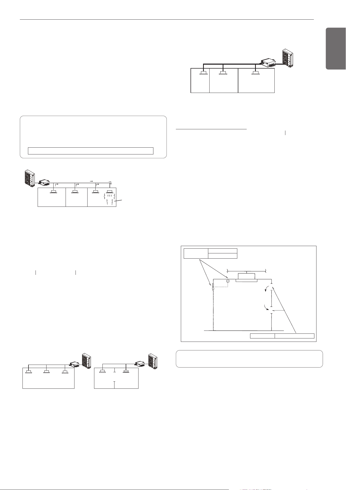
35
ENGLISH
Calculate minimum room capacity
Calculate room capacity by regarding a portion as one room or the
smaller room.
- With partition and with opening
which serve as passage of air to
adjoining room
- Without partition
Limiting concentration is the limit of Freon gas concentration
where immediate measures can be taken without hurting human
body when refrigerant leaks in the air. The limiting concentration
shall be described in the unit of Kg/m
3
(lbs/ft
3
) (Freon gas weight
per unit air volume) for facilitating calculation.
Limiting concentration: 0.44kg/m
3
(0.028lbs/ft
3
)(R410A)
Amount of additional
replenished refrigerant
Total amount of replenished
refrigerant in refrigerant
facility [kg(lbs)]
+
=
Note : In case one refrigerant facility is
divided into 2 or more refrigerant
systems and each system is
independent, amount of replenished
refrigerant of each system shall be
adopted.
Amount of replenished
refrigerant per one outdoor
unit system
Amount of replenished
refrigerant at factory shipment
Amount of additionally
replenished refrigerant
depending on piping
length or piping
diameter at customer
Outdoor unit
Indoor unit
Outdoor unit
Indoor unit
Opening
Partition
In the case of opening
without door , or 0.15
% or more openings
(to floor space) both
above and below door)
HR unit
HR unit
Outdoor unit
(No.1 system)
Flow of
refrigerant
Indoor unit
Room where refrigerant leaks
(Refrigerant of the whole No.1
system flows out.)
HR unit
- With partition and without opening which serve as passage of air to
adjoining room
Calculate refrigerant concentration
Total amount of replenishedrefrigerant
in refrigerant facility [kg(lbs)]
Capacity of smallest room
whereindoor unit is installed [m
3
(ft
3
)]
- In case the result of calculation exceeds the limiting concentration, perform
the same calculations by shifting to the second smallest, and the third small-
est rooms until at last the result is below the limiting concentration.
= Refrigerant concentration[Kg/m
3
(lbs/ft
3
)]
(R410A)
In case the concentration exceeds the limit
When the concentration exceeds the limit, change original plan or take
one of the countermeasures shown below:
• Countermeasure 1
Provide opening for ventilation.
Provide 0.15% or more opening to floor space both above and below
door, or provide opening without door.
• Countermeasure 2
Provide gas leak alarm linked with mechanical ventilator.
Reducing the outdoor refrigerant qty.
Outdoor unit
Indoor unit
Smallest
room
HR unit
Countermeasure 2
Gas leak alarm
Mechanical ventilator
Countermeasure 1
Opening effective to ventilation
Indoor unit
Pay a special attention to the place, such as a basement, etc.
where refrigerant can stay, since refrigerant is heavier than air.
Checking procedure of limiting concentration
Check limiting concentration along following steps and take appropri-
ate measure depending on the situation.
Calculate amount of all the replenished refrigerant (kg) per each refrig-
erant system.
The installer and system specialist shall secure safety against leakage
according to local regulations or standards.
The following standards may be applicable if local regulations are not
available.
Introduction
Though the R410A refrigerant is harmless and incombustible itself ,
the room to equip the air conditioner should be large to such an extent
that the refrigerant gas will not exceed the limiting concentration even
if the refrigerant gas leaks in the room.
Limiting concentration
CAUTION FOR REFRIGERANT LEAK
1,MFL69717904,영영 18. 8. 29. 영영 2:50 Page 35
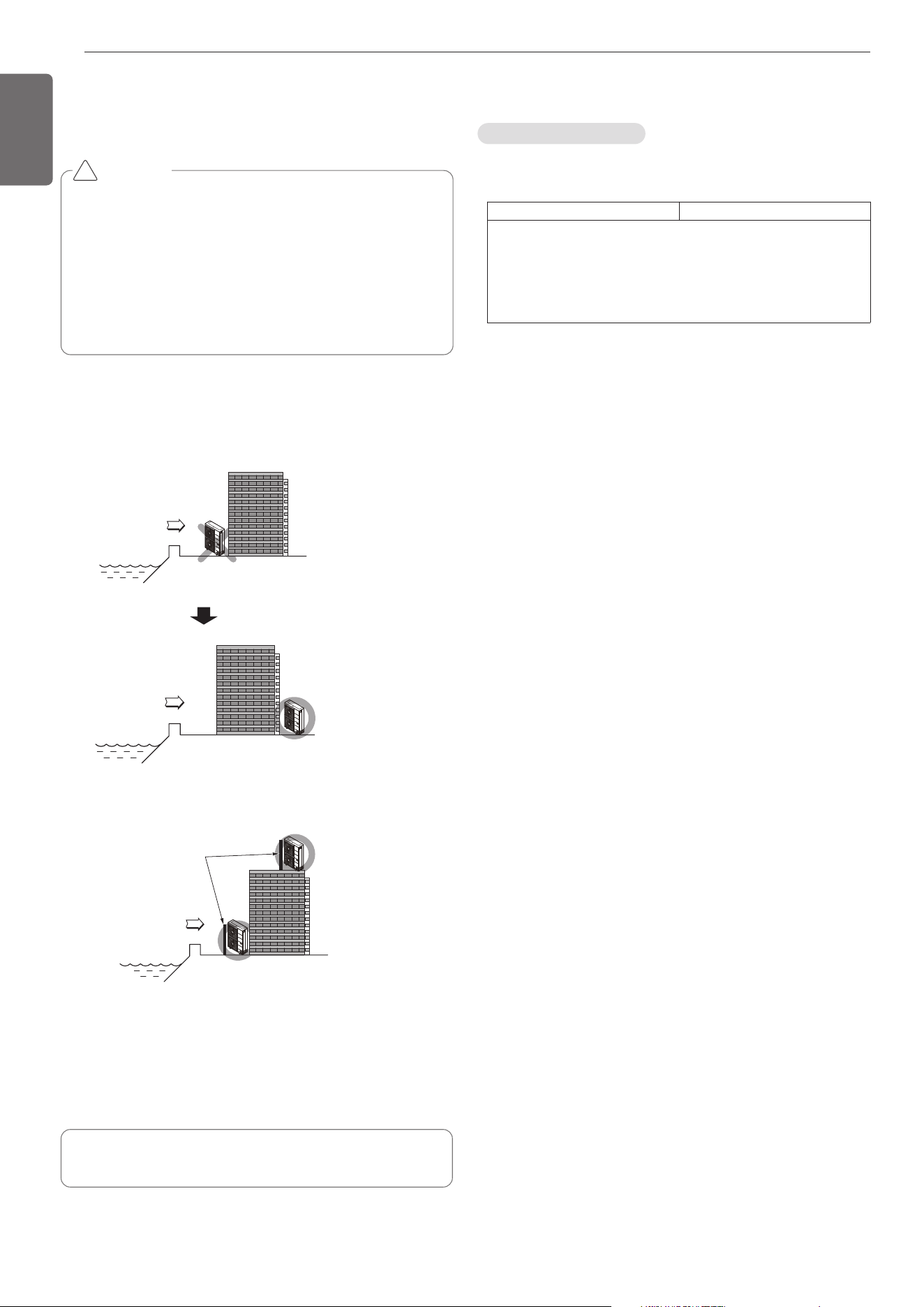
36
ENGLISH
CAUTION
• Air conditioners should not be installed in areas where
corrosive gases, such as acid or alkaline gas, are produced.
• Do not install the product where it could be exposed to sea
wind (salty wind) directly. It can result corrosion on the
product. Corrosion, particularly on the condenser and
evaporator fins, could cause product malfunction or inefficient
performance.
• If outdoor unit is installed close to the seaside, it should avoid
direct exposure to the sea wind. Otherwise it needs additional
anticorrosion treatment on the heat exchanger.
!
• Periodic ( more than once/year ) cleaning of the dust or salt
particles stuck on the heat exchanger by using water
In case, to install the outdoor unit on the seaside, set up a windbreak
not to be exposed to the sea wind.
- It should be strong enough like concrete to prevent the sea wind
from the sea.
- The height and width should be more than 150% of the outdoor unit.
- It should be keep more than 70 cm (2.3ft) of space between outdoor
unit and the windbreak for easy air flow.
Select a well-drained place.
Sea wind
Windbreak
Sea wind
Sea wind
• Product Name : Air conditioner
• Model Name :
• Additional information : Serial number is refer to the bar code on the
product.
Product Sales Name Model Factory Name
ARUx***ySSz
x = N(Heat Pump), V (Cooling only), B(Heat Recovery)
y = G(1Ø, 220-240V, 50Hz)
z = Numeric; (Series Number)
*** = Numeric; (Cooling capacity)
Product information
Airborne Noise Emission
The A-weighted sound pressure emitted by this product is below 70
dB.
** The noise level can vary depending on the site.
The figures quoted are emission level and are not necessarily safe
working levels.
Whilst there is a correlation between the emission and exposure lev-
els, this cannot be used reliably to determine whether or not further
precautions are required.
Factor that influence the actual level of exposure of the workforce in-
clude the characteristics of the work room and the other sources of
noise, i.e. the number of equipment and other adjacent processes and
the length of time for which an operator exposed to the noise. Also,
the permissible exposure level can vary from country to country.
This information, however, will enable the user of the equipment to
make a better evaluation of the hazard and risk.
Model Designation
Selecting the location(Outdoor Unit)
If the outdoor unit is to be installed close to the seaside, direct expo-
sure to the sea wind should be avoided. Install the outdoor unit on the
opposite side of the sea wind direction.
INSTALLATION GUIDE AT THE
SEASIDE
1,MFL69717904,영영 18. 8. 29. 영영 2:50 Page 36

[
Representative
] LG Electronics Inc.
EU Representative :
LG Electronics European Shared Service Center B.V.
Krijgsman 1, 1186 DM Amstelveen, The Netherlands
[Manufacturer]
LG Electronics Inc. Changwon 2nd factory
84, Wanam-ro, Seongsan-gu, Changwon-si, Gyeongsangnam-do, KOREA
1,MFL69717904,영영 18. 8. 29. 영영 2:49 Page 80