Loading ...
Loading ...
Loading ...
21
ENGLISH
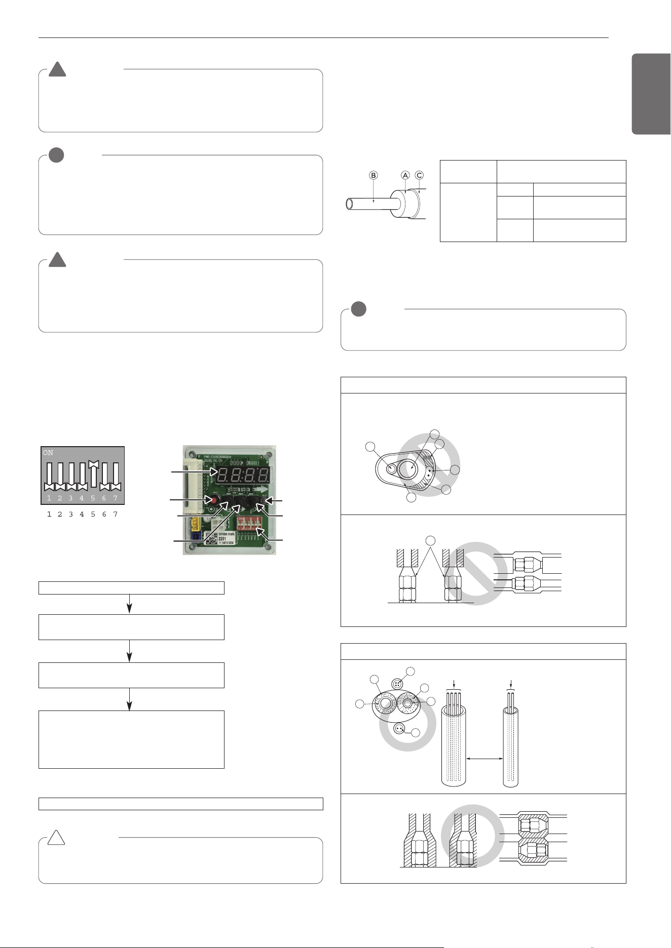
Be sure to give insulation work to refrigerant piping by covering liquid
pipe and gas pipe separately with enough thickness heat-resistant poly-
ethylene, so that no gap is observed in the joint between indoor unit
and insulating material, and insulating materials themselves. When in-
sulation work is insufficient, there is a possibility of condensation drip,
etc. Pay special attention to insulation work to ceiling plenum.
Ⓐ Heat insulation material
Ⓑ Pipe
Ⓒ Outer covering(Wind the connection part and cutting part of heat in-
sulation material with a finishing tape.)
Heat insulation
material
Adhesive + Heat - resistant poly-
ethylene foam + Adhesive tape
Outer
covering
Indoor Vinyl tape
Floor ex-
posed
Water-proof hemp cloth +
Bronze asphalt
Outdoor
Water-proof hemp cloth +
Zinc plate + Oily paint
NOTE
!
When using polyethylene cover as covering material, asphalt roof-
ing shall not be required.
Bad example
• Do not insulate gas or low pressure pipe and liquid or highpres-
sure pipe together.
• Be sure to fully insulate connecting portion.
Ⓐ
These parts are not insulated.
Ⓐ Liquid pipe
Ⓑ Gas pipe
ⓒ Power lines
ⓓ
Finishing tape
ⓔ
Insulating material
ⓕ
Communication lines
A
C
D
E
B
F
A
Good example
Ⓐ Liquid pipe
Ⓑ Gas pipe
ⓒ Power lines
ⓓ
Insulating material
ⓔ
Communication lines
Communication lines
Separation
Power lines
E
D
D
B
A
C
Thermal insulation of refrigerant piping
NOTE
!
Always add an appropriate amount of refrigerant. (For the refrigerant addi-
tional charge)
Too much or too little refrigerant will cause trouble.
To use the Vacuum Mode
(If the Vacuum mode is set, all valves of Indoor units and Outdoor units will
be opened.)
WARNING
Use a vacuum pump or Inert(nitrogen) gas when doing leakage test
or air purge. Do not compress air or Oxygen and do not use Flamma-
ble gases. Otherwise, it may cause fire or explosion.
- There is the risk of death, injury, fire or explosion.
!
WARNING
When installing and moving the air conditioner to another site,
recharge after perfect evacuation.
- If a different refrigerant or air is mixed with the original refriger-
ant, the refrigerant cycle may malfunction and the unit may be
damaged.
!
This function is used for creating vacuum in the system after compres-
sor replacement, ODU parts replacement or IDU addition/replacement.
Vacuum mode setting method
Vacuum mode off method
CAUTION
ODU operation stops during vacuum mode. Compressor can't
operate.
Service PCB DIP switch on : No.5
Select the mode using ‘▶’, ‘◀’ Button :
“SVC” Push the ‘●’ button
Select the Function using ‘▶’, ‘◀’ Button :
“Se3” Push the ‘●’ button
Start the vacuum mode : “VACC”
ODU V/V open
ODU EEV open
IDU EEV open
Dip switch off and push the reset button on Service PCB
!
DIP-SWITCH
SW01D
(reset)
SW04C
(x:cancel)
7-Segment
SW03C
(▶:forward)
SW02C
(◀:backward)
SW01C
(●:confirm)
Vacuum Mode
1,MFL69717904,영영 18. 8. 29. 영영 2:49 Page 21
Loading ...
Loading ...
Loading ...