Loading ...
Loading ...
Loading ...
13
ENGLISH
1 Always use the nitrogen.(not use oxygen, carbon dioxide, and
a Chevron gas): Please use the following nitrogen pressure
0.02MPa(2.9psi) Oxygen – Promotes oxidative degradation of
refrigerant oil. Because it is flammable, it is strictly prohibited
to use Carbon dioxide – Degrade the drying characteristics of
gas Chevron Gas – Toxic gas occurs when exposed to direct
flame.
2 Always use a pressure reducing valve.
3 Please do not use commercially available antioxidant.
The residual material seems to be the oxide scale is ob-
served. In fact, due to the organic acids generated by oxida-
tion of the alcohol contained in the anti-oxidants, ants nest
corrosion occurs. (causes of organic acid
’
alcohol + copper
+ water + temperature)
CAUTION
!
Refrigerant
Charging Port
Liquid pipe
High Pressure gas pipe
Low Pressure gas pipe
CAUTION
Please block the pipe knock outs of the front and side panels after
installing the pipes.
(Animals or foreign objects may be brought in to damage wires.)
!
WARNING
• Always careful not to leak the refrigerant during welding.
• The refrigerant generates poisonous gas harmful to human body
if combusted.
• Do not perform welding in a closed space.
• Be sure to close the cap of the service port to prevent gas leak-
age after the work.
!
Installation procedure for HR unit
1 Using an insert-hole-in- anchor, hang the hanging bolt.
2 Install a hexagon nut and a flat washer (locally-procured)to the
hanging bolt as shown in the figure in the bottom, and fit the main
unit to hang on the hanger metal.
3 After checking with a level that the unit is level, tighten the hexa-
gon nut.
* The tilt of the unit should be within ±5° in front/back and left/right.
4 This unit should be installed suspended from ceiling and side A
should always be
facing up.
5 Insulate not used pipes completely as shown in the figure.
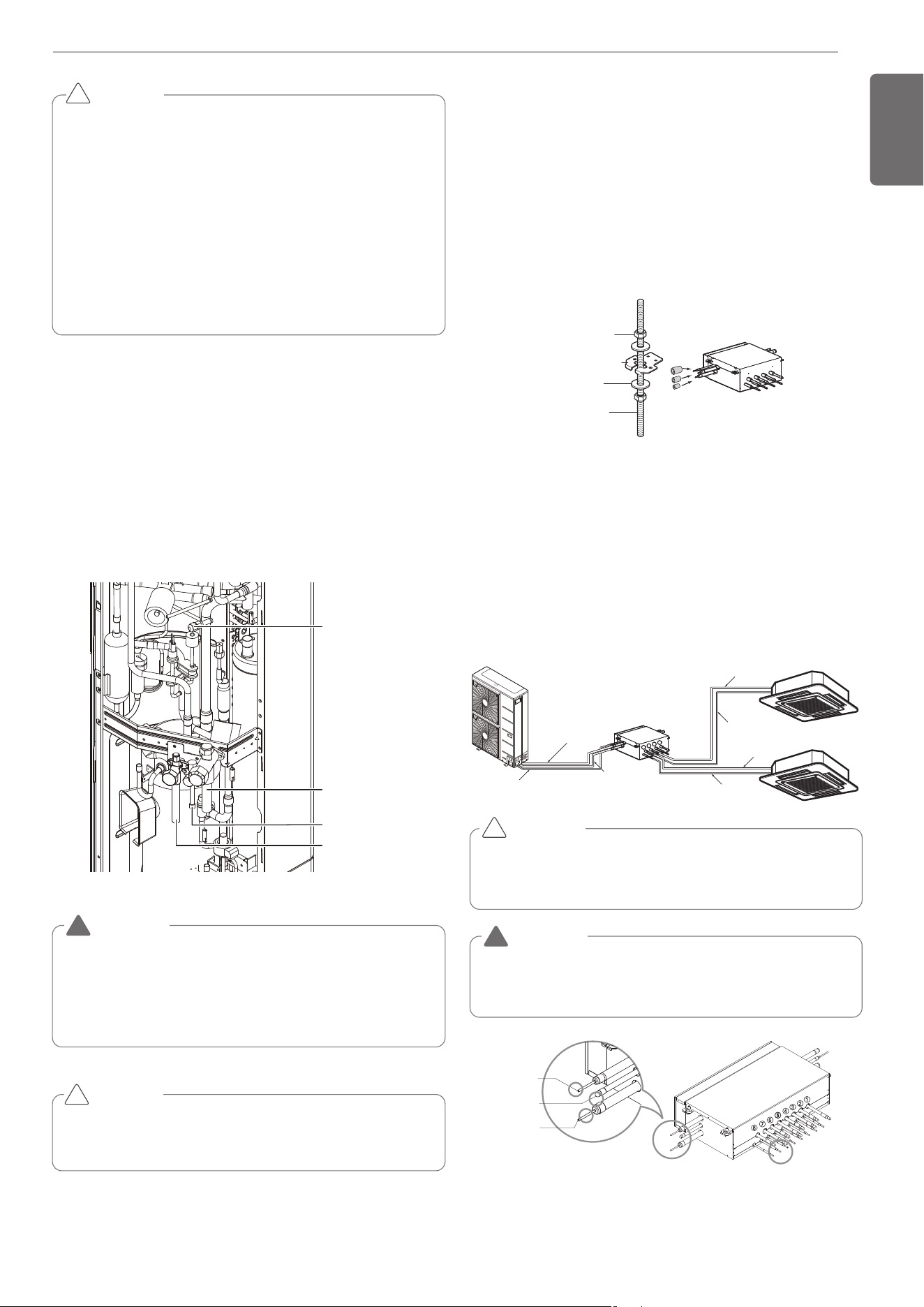
Installation of Outdoor Unit, HR Unit and In-
door Unit Refrigerant Pipe
3 pipes are connected to the HR unit from the outdoor unit, classified
into liquid pipe, low pressure gas pipe and high pressure gas pipe de-
pending on status of refrigerant passing through the pipe.
You must connect 3 pipes from outdoor unit to HR unit.
For connection between indoor unit and HR unit, you must connect
both liquid pipe and gas pipe from the HR unit to the indoor unit. In this
case, connect them to the indoor unit starting from No.1 connection
port of the HR unit (the port number is displayed on ports of the HR
unit). Use auxiliary flare as annexed parts in connection to the indoor
unit.
Six-sided Nut
(M10 or M8)
Hanger metal
Hanger metal
Hanger metal
Flat washer
Flat washer
Flat washer
(M10)
Hanging bolt
Hanging bolt
Hanging bolt
(M10 or M8)
A
Insulation
Gas pipe
Gas pipe
Liquid pipe
Liquid pipe
HR Unit
1
2
3
4
Low pressure
Gas pipe
Liquid pipe
High pressure
Gas pipe
Whenever connecting the indoor units with the HR unit, install the in-
door units in numerical order from No.1.
Ex) In case of installing 3 indoor units : No. 1, 2, 3 (O), No. 1, 2, 4 (X),
No.1, 3, 4 (X), No.2, 3, 4 (X).
CAUTION
!
WARNING
Before brazing work, remove gas in the HR Unit by cutting the three
pipes in the small circles on the figure.
If not, it may cause injuries.
Remove the caps before connecting pipes.
!
REFRIGERANT PIPING INSTALLATION
Precautions on Pipe connection / Valve operation
Pipe connection is done by connecting from the end of the pipe to the
branching pipes, and the refrigerant pipe coming out of the outdoor
unit is divided at the end to connect to each indoor unit and HR unit.
Flare connection for the indoor unit, and welding connection for the
outdoor pipe and the branching parts. (Including HR unit)
- Use hexagonal wrench to open/close the valve.
Gas pipe Ø15.88– Ø12.7
Liquid pipeØ9.52– Ø6.35
Brazing Type
Liquid pipe
High pressure
gas pipe
Low pressurse
gas pipe
(Brazing Type)
1,MFL69717904,영영 18. 8. 29. 영영 2:49 Page 13
Loading ...
Loading ...
Loading ...