Loading ...
Loading ...
Loading ...
18
ENGLISH
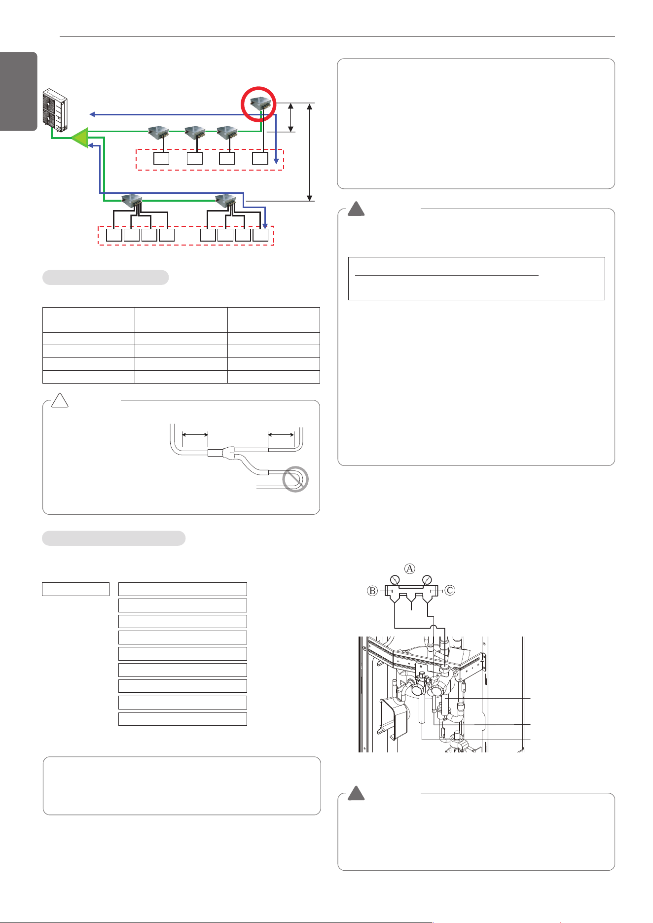
• Keep the 40m(131ft) distance from the first branch to the farthest in-
door.
1) under 40m(131ft)
Keep the sum of indoor capacity under 58kW(192 kBtu/h).
Indoor
Unit
Indoor
Unit
Indoor
Unit
Indoor
Unit
Indoor
Unit
Indoor
Unit
Indoor
Unit
Indoor
Unit
Indoor
Unit
Indoor
Unit
Indoor
Unit
Indoor
Unit
1) under 40m(131ft)
Y branch
5m(16ft)
15m(49ft)
Keep the sum of indoor capacity under 58kW(192 kBtu/h).
Indoor Unit Connection
Indoor Unit connecting pipe from branch (a,b,c,d,e,f)
Indoor Unit capacity
[kW(Btu/h)]
Liquid pipe
[mm(inch)]
Gas pipe [mm(inch)]
≤ 5.6(19,100)
Ø6.35(1/4) Ø12.7(1/2)
< 16.0(54,600) Ø9.52(3/8) Ø15.88(5/8)
< 22.4(76,400) Ø9.52(3/8) Ø19.05(3/4)
< 28.0(95,900) Ø9.52(3/8) Ø22.2(7/8)
CAUTION
• Bending radius should be
at least twice the diameter
of the pipe.
• Bend pipe after 500mm
(19-5/8inch) or more from
branch(or header).
Do not bend U type.
It may cause Performance
unsatisfactory or noise.
!
500mm
(19-5/8inch)
or more
500mm
(19-5/8inch)
or more
The amount of Refrigerant
The calculation of the additional charge should take into account the
length of pipe and CF(correction Factor) value of indoor unit.
Amount refrigerant of Indoor units
Example) 4Way Ceiling Cassette 14.5kW -1ea, Ceiling concealed
Duct 7.3kW-2ea, Wall Mounted 2.3kW-4ea
CF = 0.64 × 1 + 0.26 × 2 + 0.24 × 4 = 2.12kg(4.67lbs)
Attach the additional refrigerant table of IDU.
Additional charge(kg) = Total liquid pipe : Ø25.4 mm (1.0 inch) x
0.480 kg/m (0.323 lbs/ft)
+ Total liquid pipe : Ø22.2 mm (7/8 inch) x
0.354 kg/m (0.238 lbs/ft)
+ Total liquid pipe : Ø19.05 mm (3/4 inch) x
0.266 kg/m (0.179 lbs/ft)
+ Total liquid pipe : Ø15.88 mm (5/8 inch) x
0.173 kg/m (0.116 lbs/ft)
+ Total liquid pipe : Ø12.7 mm (1/2inch) x
0.118 kg/m (0.079 lbs/ft)
+ Total liquid pipe : Ø9.52 mm (3/8inch) x
0.061 kg/m (0.041 lbs/ft)
+ Total liquid pipe : Ø6.35 mm (1/4 inch) x
0.022 kg/m (0.015 lbs/ft)
+ Number of installed HR unit x
0.5 kg (1.1 lbs)
+ CF value of indoor unit
WARNING
• Regulation for refrigerant leakage
: the amount of refrigerant leakage should satisfy the following
equation for human safety.
If the above equation can not be satisfied, then follow the follow-
ing steps.
• Selection of air conditioning system: select one of the next
- Installation of effective opening part
- Reconfirmation of Outdoor Unit capacity and piping length
- Reduction of the amount of refrigerant
- Installation of 2 or more security device (alarm for gas leakage)
• Change Indoor Unit type
:
installation position should be over 2m(6.6ft) from the floor (Wall
mounted type ’ Cassette type)
• Adoption of ventilation system
: choose ordinary ventilation system or building ventilation sys-
tem
• Limitation in piping work
: Prepare for earthquake and thermal stress
Liquid pipe
High Pressure gas pipe
Low Pressure gas pipe
Ⓐ Manifold Gauge
Ⓑ Low pressure side Handle
Ⓒ High pressure side Handle
!
WARNING
• Pipe to be vacuumed : gas pipe, liquid pipe
• If the refrigerant amount is not exact, it may not operate
properly.
• If additionally bottled refrigerant amount is over 10%, condenser
burst or insufficient indoor unit performance may be caused.
!
Volume of the room at which Indoor Unit of
the least capacity is installed
Total amount of refrigerant in the system
≤0.44kg/m
3
(0.028lbs/ft
3
)
Refrigerant charging
※6 & 8 Branches Model :
1.0kg/EA (2.2 lbs/EA)
1,MFL69717904,영영 18. 8. 29. 영영 2:49 Page 18
Loading ...
Loading ...
Loading ...