Loading ...
Loading ...
Loading ...
23
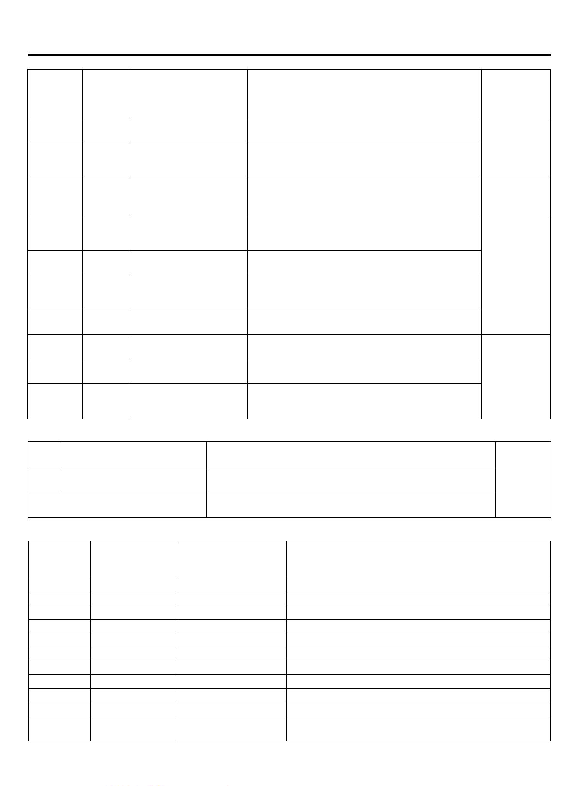
Failure code
Digital tube
indication
on master
unit
Indication
on wired
controller
(hex)
Failure code denition Failure description Remarks
114 114
Voltage too low of DC bus
line of transducer
Voltage of power source is too low
3 times in an
hour, conrm
failure; once
conrmation,
un-resumable
115 115
Voltage too high of DC
bus line of transducer
Voltage of power source is too high
116 116
Communication abnormal
between transducer and
control PCB
Communication is disconnected Resumable
117 117
Transducer over current
(software)
Compressor startup fails for 5 times continuously, or
compressor is running down till stops caused by over
current or over heat
3 times in an
hour, conrm
failure; once
conrmation,
un-resumable
118 118
Compressor startup
failure
The sensor used for current detecting of transducer
is abnormal, disconnected or incorrectly connection
119 119
Detecting circuit of
transducer current is
abnormal
Current detection sensor of frequency controller is
abnormal or unconnected or connected wrongly.
120 120
Power supply of
transducer abnormal
Power supply of transducer is broken down instantly
121 121
Power supply of inverter
board is abnormal
Power supply of inverter board is broken down
instantly
3 times in an
hour, conrm
failure; once
conrmation,
un-resumable
122 122
Radiator temp.sensor of
transducer abnormal
Resistor of temp.sensor abnormal or temp.sensor
disconnected
123 123
Transient over current in
IPM module rectier side
hardware
Transient over current in IPM module rectier side
hardware
When there is no failure, if the starting condition can not be met, digital tube on master unit will display stand-by code:
555.0
Standby state of capacity
overmatch
When capacity is over 130% or lower than 50%, the system is
standby.
Resumable555.1
Outdoor ambient temperature
too high (heating)
Ta>80.6°F, Standby
555.3
Outdoor ambient temperature
too high or too low (cooling)
Ta>129.2°F or Ta<14°F, Standby
Indication on
master unit
Indication on wired
controller
Flash times of LED5 on
indoor PCB/timer LED
on remote receiver
Failure code denition
01 01 1 Indoor ambient temp. sensor Ta failure
02 02 2 Indoor coil temp. sensor Tc1 failure
03 03 3 Indoor coil temp. sensor Tc2 failure
04 04 4 Indoor TW sensor failure
05 05 5 Indoor EEPROM failure
06 06 6 Communication between indoor and outdoor failure
07 07 7 Communication between indoor and wired controller failure
08 08 8 Indoor drainage failure
09 09 9 Indoor repeated address
0A 0A 10 Indoor repeated central control address
Outdoor
failure code
Outdoor failure
code
20 Outdoor corresponding failure
Indoor failure code list
Loading ...
Loading ...
Loading ...