Loading ...
Loading ...
Loading ...
©2017 Pinnacle Climate Technologies 9 Vented Gas Log Appliance User’s Manual
Installation (cont.)
BEFORE INSTALLING THE APPLIANCE
• Turn o the gas supply to the replace or rebox.
• Clean the replace oor and chimney, seal any ash, and
clean out the doors to protect from any down drafts.
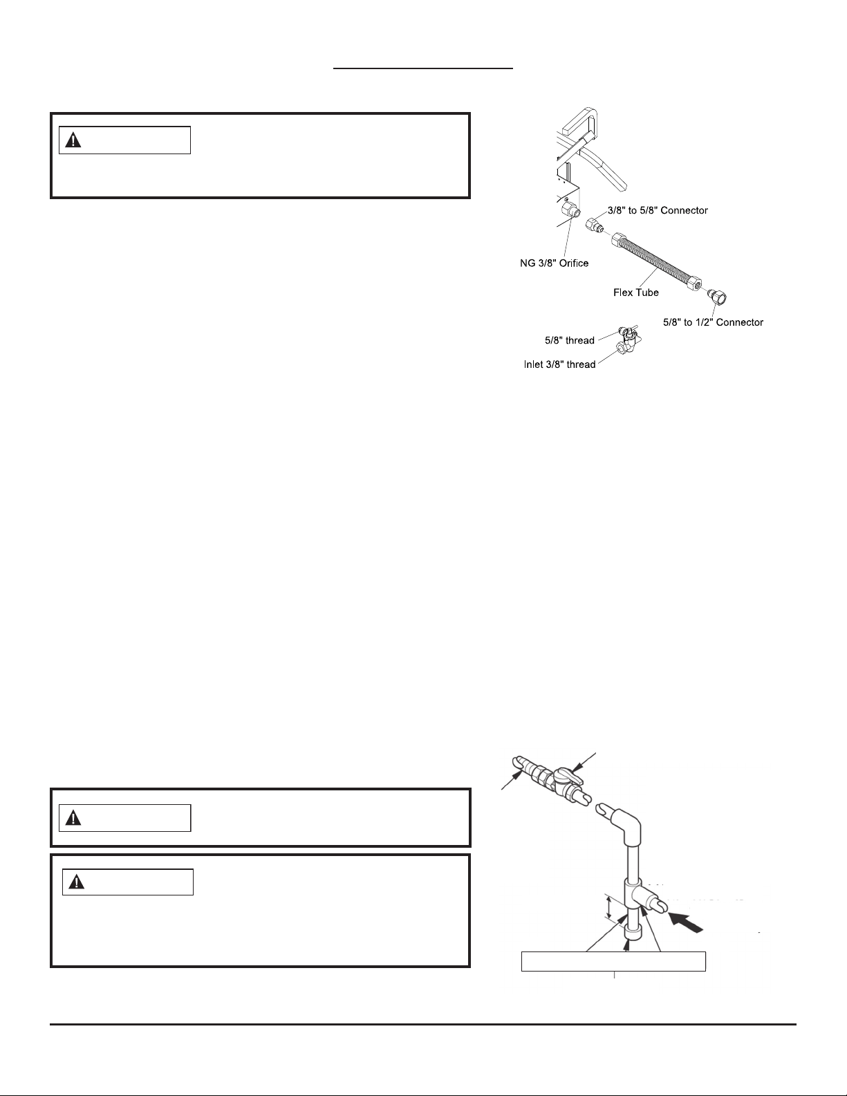
INSTALLATION AND GAS CONNECTION* (See Fig. 6 & 7)
1. Place the burner pan assembly in the center of the replace
oor. The front of the pan must face forward.
2. Install the 3/8" orice tting onto the burner inlet tting using
thread sealant on male threads of the burner inlet tting.
3. If the gas supply has an equipment shuto valve within
reach of lighting the log set, then thread the 1/2" connector
to the shuto valve. Use thread sealant.
4. If the gas supply does not have an equipment shuto valve
within reach, a manual gas valve is provided. Connect the
manual gas valve to gas supply pipe. Use thread sealant.
5. Attach the gas ex tube to the gas supply. Shape the tube
to attach to the orice tting.
CONNECTION TO GAS SUPPLY
Installation Items Needed:
• piping (check local codes)
• sealant (resistant to natural gas)
• equipment shuto valve
• test gauge connection
Installation must include an equipment shuto valve, union,
and plugged 1/8" NPT tap. Locate the NPT tap within reach
for test gauge hook up. The NPT tap must be upstream from
the appliance (see Figure 7).
* In compliance with ANS Z21.60•CSA2.26 and National Fuel Gas Code, Section 6.
Before installing the appliance, have the
fireplace and chimney professionally cleaned
to remove any soot, creosote, ashes, or other
obstructions. Perform this cleaning annually after installation.
WARNING
A qualified service person must connect the
appliance to gas supply. Follow all local codes.
WARNING
Only use a new black iron or steel pipe.
Internally-tinned copper tubing may be
used in certain areas. Check local codes. To allow proper gas
volume to the appliance, use a pipe of 1/2" diameter or greater.
Loss of pressure occurs if the pipe is too small.
CAUTION
• sediment trap
• tee joint
• pipe wrench
• adjustable (crescent)
wrench or pliers
IMPORTANT: Install the equipment shuto valve
in an accessible location. The equipment shuto
valve is used for turning on or shutting o the
gas to the appliance.
Lightly apply pipe joint sealant to the male
threads. This prevents excess sealant from going
into the pipe. A clogged burner injector may
result from excess sealant in the pipe.
Install the sediment trap in the supply line (see
Fig. 7). Locate the sediment trap so it can easily
be cleaned and where trapped material is unlike-
ly to freeze. A sediment trap traps moisture and
contaminants, keeping them from going into the
appliance controls. The appliance may not oper-
ate correctly if the sediment trap is not installed
or is installed incorrectly.
7''
(5.5''
Equipment Shuto Valve With
1/8" NPT Tap
Approved
Flexible
Gas Line
or 1/2"
Black Pipe
3" Minimum
Sediment Trap
Propane/LP
From External
Regulator (11"
W.C. to 14" W.C
Pressure)
Natural
From Gas Meter
(7" W.C.** to
10.5" W.C.
Pressure)
Fig. 6
Fig. 7
Pipe Nipple Cap Tee Joint
Loading ...
Loading ...
Loading ...