
Loading ...
Loading ...
Loading ...
©2017 Pinnacle Climate Technologies 10 Vented Gas Log Appliance User’s Manual
Installation (cont.)
CHECKING GAS CONNECTIONS
Pressure Testing Gas Supply Piping System
Test Pressures in Excess Of 1/2 PSIG (3.5 kPa):
1. Disconnect the appliance, including the main gas valve (control valve) and equipment shuto valve,
from the gas supply piping system. Pressures greater than 1/2 PSIG will damage the regulator.
2. Cap o the open end of the gas pipe where the equipment shuto valve was connected.
3. Open the gas supply tank valve or use compressed air to pressurize the supply piping system.
4. Check all joints of the gas supply piping system. Use a mixture of liquid soap and water in the gas joints
to check for leaks—bubbles may indicate a leak.
5. Immediately correct all leaks.
6. Reconnect the appliance and equipment shuto valve to gas supply. Check reconnected ttings for leaks.
Test Pressures Equal To or Less Than 1/2 PSIG (3.5 kPa):
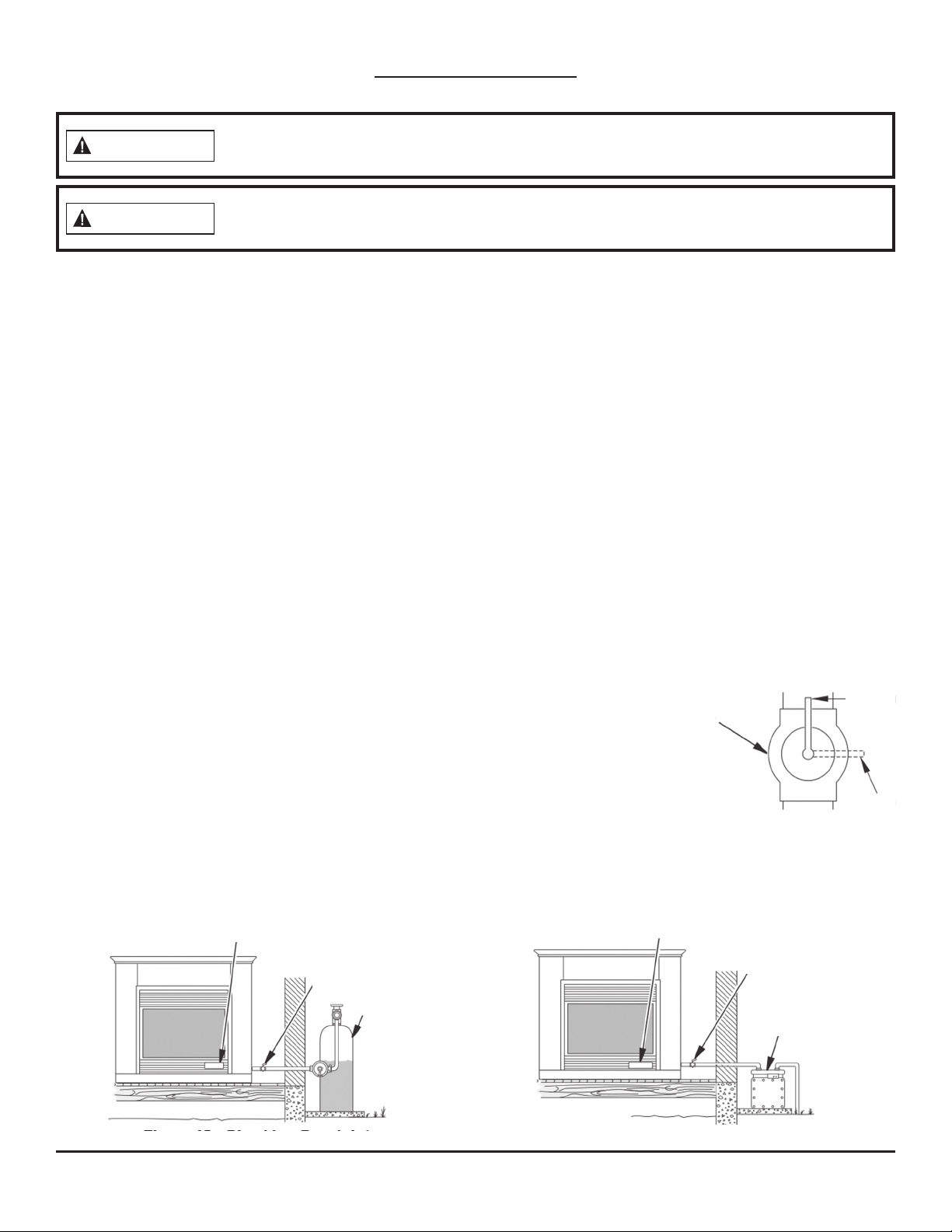
1. Close equipment shuto valve (see Fig. 8).
2. Open the gas supply tank valve or use compressed air to pressurize the supply piping system.
3. Check all joints from the gas meter to equipment shuto valve (see Fig. 9.1 & 9.2).
4. Use a mixture of liquid soap and water in the gas joints to check for leaks—bubbles may indicate a leak.
5. Immediately correct all leaks.
Pressure Testing Appliance Gas Connections:
1. Open the equipment shuto valve (see Fig. 8).
2. Open the gas supply tank valve.
3. Ensure the control knob of the appliance is in the OFF position.
4. Check all joints from the equipment shuto valve to the control valve
(see Fig. 9.1 & 9.2). Use a mixture of liquid soap and water in the gas
joints to check for leaks—bubbles may indicate a leak.
5. Light the appliance (see OPERATION, page 13). Check all other internal
joints for leaks.
6. Turn o the appliance (see TO TURN OFF GAS TO THE APPLIANCE, page 13).
After installing or servicing the appliance, test all gas piping and connections for leaks.
Immediately correct all leaks.
WARNING
Never use an open ame to check for a leak. Apply a mixture of liquid soap and water to
all joints. There may be a leak if bubbles form. Immediately correct all leaks.
WARNING
Equipment
Shuto
Valve
Open
Closed
Fig. 8
Equipment
Shuto
Valve
Propane/
LP Supply
Tank
Gas Control Valve
Fig. 9.1—Checking Gas Joints (Propane/LP Only)
Gas Control Valve
Equipment
Shuto Valve
Gas Meter
Fig. 9.2—Checking Gas Joints (Natural Gas Only)
Loading ...
Loading ...
Loading ...