Loading ...
Loading ...
Loading ...
13
14
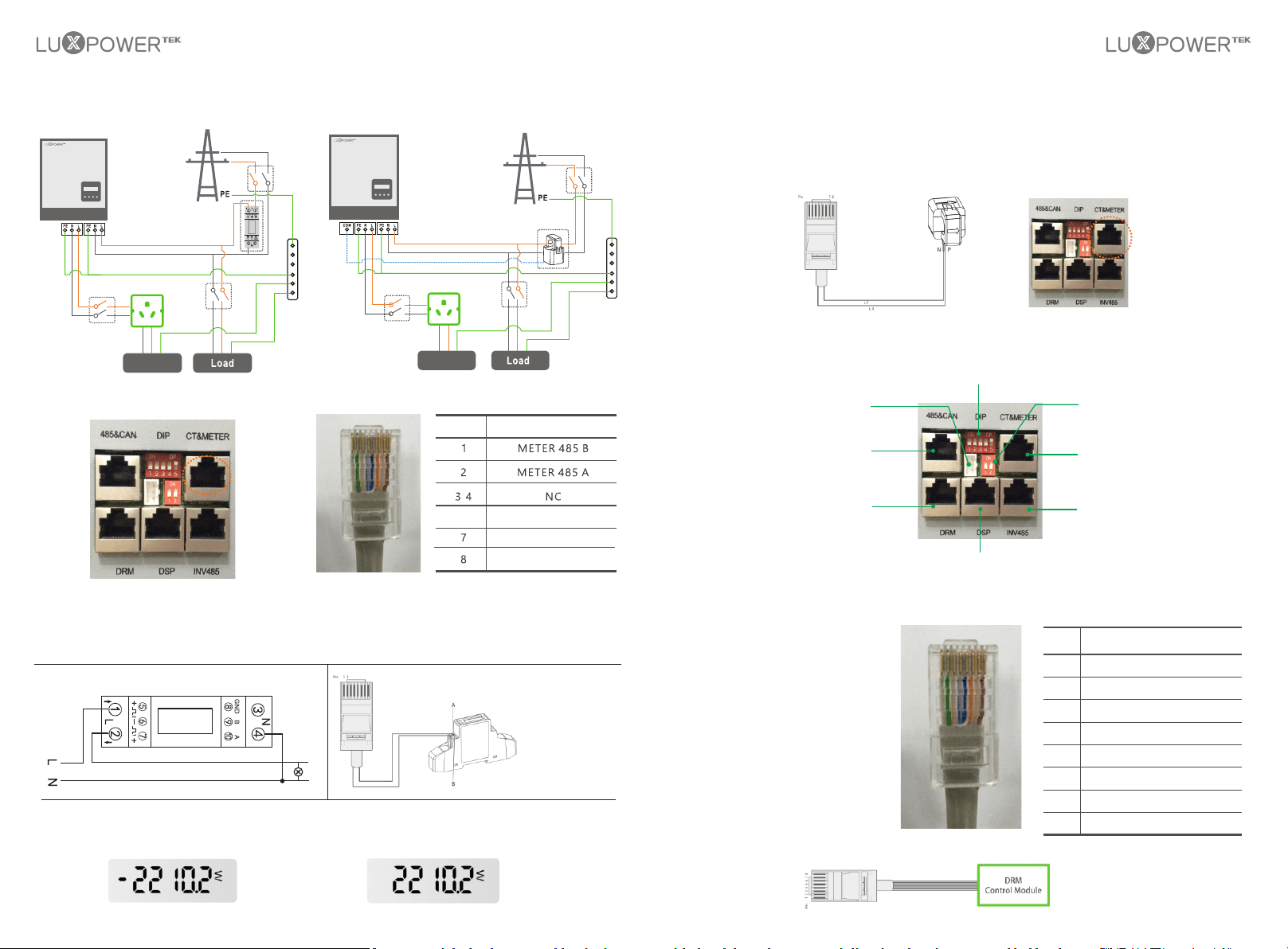
3.4.6 Meter and CT Connection
In a completed installed on-grid energy storage system, the CT or Meter should be installed. The CT or Meter
should installed in the right position as below picture
The communication port for communicate with
meter or CT clamp is as below:
Pin
Function Description
3.4.6.1 Connect the Meter
Step1. Connect the meter in the LN line as below
Inverter
Side
AC Grid
Side
3.4.6.2 Connect the CT
1
2
Step2. Connect the communication cable
between inverter and meter, and plug the
RJ45 to communication port
3.4.7 Communication Connection
Interface Overview
3.4.7.1 DRMs Connection
DRMs is short for ‘inverter demand
response modes’, and it is a mandatary
requirements for inverters in Australia
Pin
1 2
3
4
5
6 7 8
RJ45 Terminal Configuration of Meter/CT Communication
The functional interfaces overview of the meter is shown in below figure. Now Luxpower only support
EASTRON SDM120 and SDM630- Modbus Modbus model meter.
Step3. Check the connection. When the meter displays -xxxxW as below figure shows, the hybrid
inverter is feeding power to the grid.and when it displays xxxxW, it means the house load is using
energy from grid.
Battery Communication Interface
Safety Standard Configuration Switch
Balancing Resistor
Configuration Switch
CT and Meter
Communication Interface
Parallel cable
communication Interface
Parallel cable
communication Interface
DRM Interface
DRM Communication Interface Overview
/
For the CT clamp connection, we need to put the CT clamp in the L cable and the arrow printed on the CT
should point to inverter.
Now Luxpower support two ratio 1000:1 and 3000:1 CT clamps . For default, the ratio is 1000:1, if you install
another CT clamp, please set it in the monitor system or LCD.
For the CT clamp cable, users can use the normal net cable to extend the length if the original length is not
enough. The longest distance can be 100m.
Generator Controller Box Interface
Pin
1 2
3
4
5
6 7 8
RJ45 Terminal Configuration of DRM
Pin
1
Function Description
2
3
4
DRM15
DRM26
DRM37
DRM48
5
6
7
8
RefGen
DRM0
+12V
GND-S
5/6
Reserved
CTN
CTP
UPS Load
UPS Load
Loading ...
Loading ...
Loading ...