Loading ...
Loading ...
Loading ...
17
3.4.8 Grounding
A second protective earth (PE) terminal is equipped at the side of the inverter.
Be sure to connect this PE terminal to the PE bar for reliable grounding.
When you finish all of above chapters of connections,
please don’t forget to install the protective shell back
to the inverter. This step can be carried out either after
finished grounding or commissioning of the system.
Cable Requirements
3-6mm² copper cable or 10-16mm² aluminum cable.
Install the Protective Shell
17
4. Operation Guide
4.1 Operation Mode
Users can have different settings to satisfy their demands, the working modes is as below:
Operation
mode
Related Settings
Explanation Application Notes
Self usage
(Default mode)
The priority of the PV energy will be Load >battery
> grid, which means the energy generated by PV
will be mainly used by local loads, and rest will be
stored in the battery, excessive power will be feed
back into the grid.
Effective when charge
priority and force time
charge/discharge are
disable
Charge priority
Charge Priority and
related time, SOC
Force time
Force charge/discharge
enable and disable, and
related time SOC
This mode suits for situation
where the price difference of
energy is big under Time of
Use (To U)
Micro Grid
mode(Genset)
When used in pure off grid application, users may
connect the Gen set output to grid input , when
battery SOC is low. Inverter will use generator to
take the load and charge the battery.
Micro grid enable
/disable
Area where is no grid and
there is utility
Off grid mode
Inverter will switch to off grid mode
automatically when there is no grid.
UPS enable Area where is no grid
The priority of the PV energy will be battery >Load >grid,
which means the energy generated by PV will be used to
charge the battery first, and then used by local loads,
excessive power will be feed back into the grid.
User can set the charging and discharging time and
priority of energy use under Force Time Use mode .
This is also used to flexibly make use of your system
by customized settings by the users.
increase the self consumption
rate and reduce the energy bil
significantly
When the load shedding
always happens, users need
to charge battery first
18
4.2 LCD operation and settings
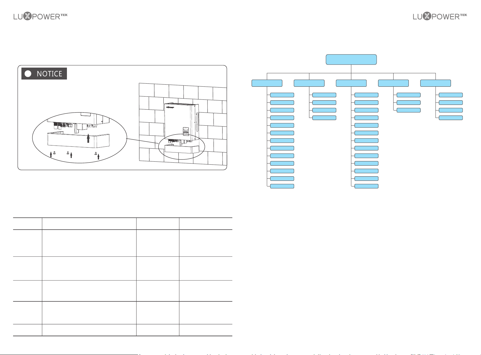
4.2.1 LCD Menu Structure Overview
Display Menu
Fault
Flash
PV Grid On
PV Charge
PV Charge+ Grid On
Battery Grid On
PV+Battery Grid On
AC Charge
PV+AC Charge
Battery Grid Off
PV Battery Grid Off
PV Charge Grid Off
Standby
PV Info
Battery Info
Grid Info
UPS Info
PV Charge+ Grid On
Set COM Address
Set Time
Set Language
Set Battery
Set PV Input
Set UPS Mode
Set AC Charge
Model
Ser No.
FW Version
Bulid
Error Record
Energy Record
Alarm Record
History Info Product Info
Status
Measured Info
Setting
PV Charge+ Grid On
Set Feed-in grid
Set EOD
Set CT or Meter
Set Micro-Grid
Set Parasys Role
Set Parasys Phase
(For MG model)
(For MG model)
4.2.2 Status and Parameter show in LCD
a) Standby
Inverter is waiting for sufficient DC voltage from the PV or battery. It occurs when the sunlight is not
sufficient to make the inverter working and battery SOC is low.
b) Fault
Fault occurred with the inverter or system. Inverter will stop working unless fault or error is fixed.
Detailed information and troubleshooting please refer to Chapter 8. Troubleshooting & Maintenance.
c) Flash
When upgrading the firmware of inverter, the inverter will working at flash status.
There are 2 ways to upgrade the firmware of inverter:
- Remote upgrading based on remotely connected server through the wireless communication module.
- Locally upgrading through RS485 communication connection.
Loading ...
Loading ...
Loading ...