Loading ...
Loading ...
Loading ...
11
12
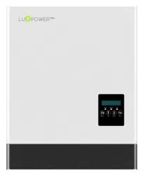
3.4.4 Grid Connection
a) Lead the AC cable though cable gland, seal ring
and threaded sleeve, and fully insert the conductors
to corresponding terminals on connection terminal
and tighten the screws.
c) Assemble the GRID connector and make sure that
the rib of the terminal block and the groove on the
housing engage perfectly until a ‘click’ is heard or felt.
a) Align the GRID connector and AC terminal and mate them together by hand until a ‘click’ is heard or felt .
c) Connect the PE conductor to grounding electrode, and connect N and L conductors to AC breakers.
d) Connect the AC breakers to the AC grid.
3.4.5 UPS/Back-up Connection
Cross-section Diameter
2
4 - 6 mm 2 mm - 2.6 mm
Cable Requirements:
Step 1: Assemble the AC connector.
AC Connector Structure Overview
b) Refer to below figure and confirm the AC cables
are correctly connected. The difference between the
AC connector and UPS connector is that AC connector
has a “Grid” mark on it and UPS does not
Step 2: Install the AC connector
b) An AC breaker (AC switch) should be installed between inverter and the grid, confirm the AC breaker
is working normally before connect the AC cable from inverter to AC breaker. Turn off the AC breaker
and keep it open.
Cable requirements
Step 1: Assemble and install the UPS connector process is the same as AC connectors which show
in Chapter 5.4 Grid Connection (the Step 1 and Step 2). Finish the UPS connector assembling and
installation first of all.
Step 2:UPS wiring.
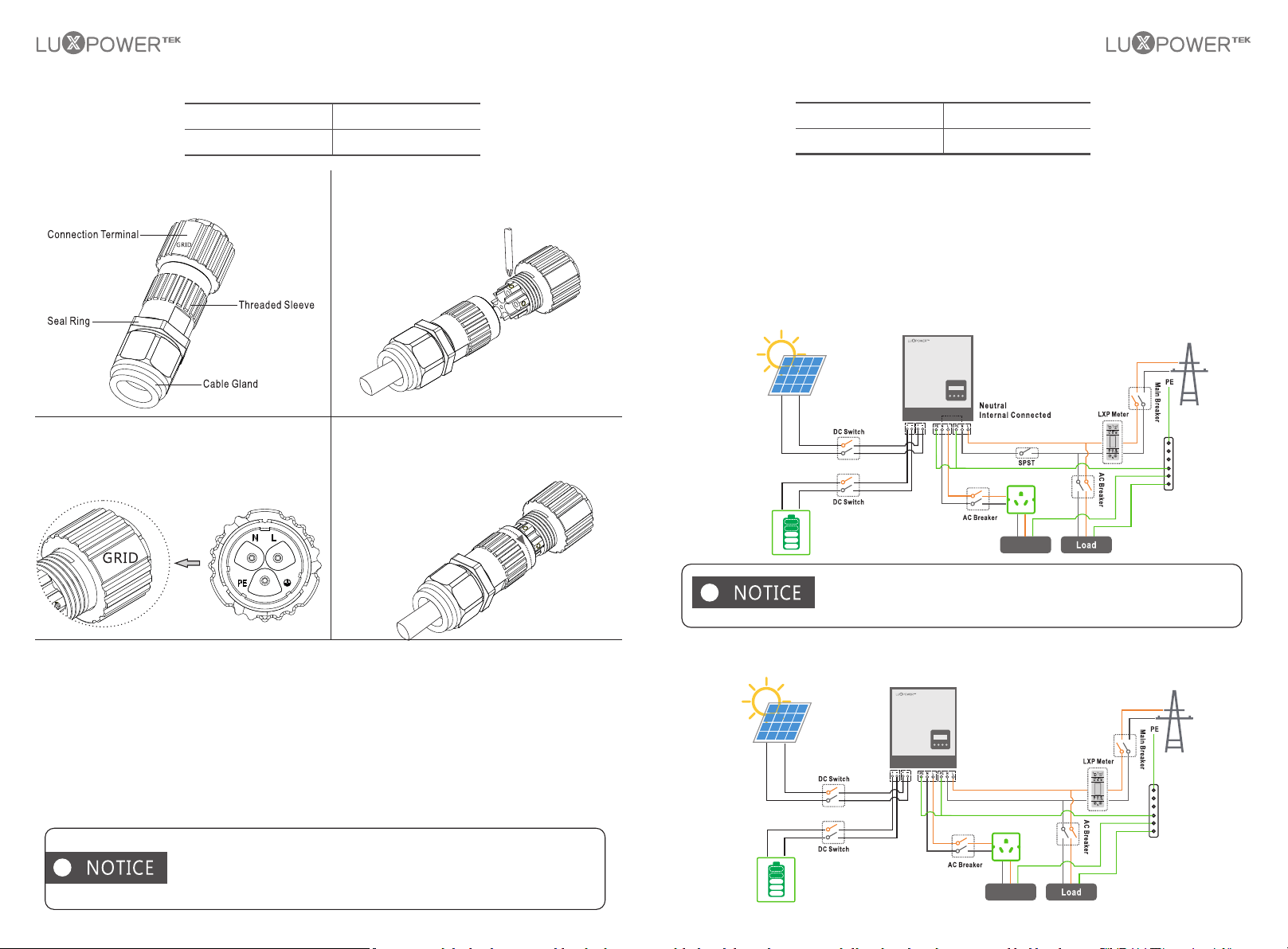
There are 2 different UPS wiring mode in accordance with different local or national rules, standards
or regulations. Please choose the suitable wiring mode according to the local requirements.
Mode A:Neutral line of alternative supply must not be isolated or switched.
The connection diagram of UPS Connection Mode A is shown in below figure.
Backup loads neutral and grid neutral are connected internally inside the
inverter, so the installer do not need to connect them outside. The power
of backup load should be lower than 5kW.
Mode B:Neutral line of alternative supply can be isolated or switched.
The connection diagram of UPS Connection Mode B is shown in below figure.
Cross-section Diameter
2
4 - 6 mm 2 mm - 2.6 mm
Cross-section Diameter
2
4 - 6 mm
2 mm - 2.6 mm
Cross-section Diameter
2
4 - 6 mm
2 mm - 2.6 mm
UPS Load
UPS Load
e) You must install a separate single-phase circuit-breaker or other load disconnection unit foe each
inverter in order to ensure that the inverter can be safely disconnected under load.
The inverter has the function of detecting residual current and protecting
the inverter against residual current. If your inverter has to equip a AC
breaker which has the function of detecting residual current, you must
choose a AC breaker with the rating residual current more than 300mA.
Loading ...
Loading ...
Loading ...