Loading ...
Loading ...
Loading ...
Due to our policy of continuous product innovation, some specications may change without notication.
©LG Electronics U.S.A., Inc., Englewood Cliffs, NJ. All rights reserved. “LG” is a registered trademark of LG Corp.
DUCTED | 69
Refrigerant Piping Design and Best Practices
REFRIGERANT PIPING DESIGN
Refrigerant Piping System Layout
Brazing Practices
All joints are brazed in the field. Single Zone Ducted refrigeration system com-
ponents contain very small capillary tubes, small orifices, electronic expansion
valves, oil separators, and heat exchangers that can easily become blocked.
Proper system operation depends on the installer using best practices and utmost
care while assembling the piping system.
• While brazing, use a dry nitrogen purge operating at a minimum pressure of three
(3) psig and maintain a steady flow.
• Blow clean all pipe sections with dry nitrogen prior to assembly.
• Do not use a saw to cut pipe; use a tubing cutter. De-burr and clean all cuts
before assembly.
• Store pipe stock in a dry place. Keep pipe capped and clean.
• Use adapters to assemble different sizes of pipe.
• Do not use flux, soft solder, or anti-oxidant agents.
• Use a 15% silver phosphorous copper brazing alloy to avoid overheating and produce good flow.
• Protect isolation valves, electronic expansion valves, and other heat-sensitive control components from excessive heat with a wet rag or a
heat barrier spray product.
Pressure-reducing
Valve
Packless
Valve
Tape
Nitrogen
Pipe to
be brazed
Refrigerant
Piping
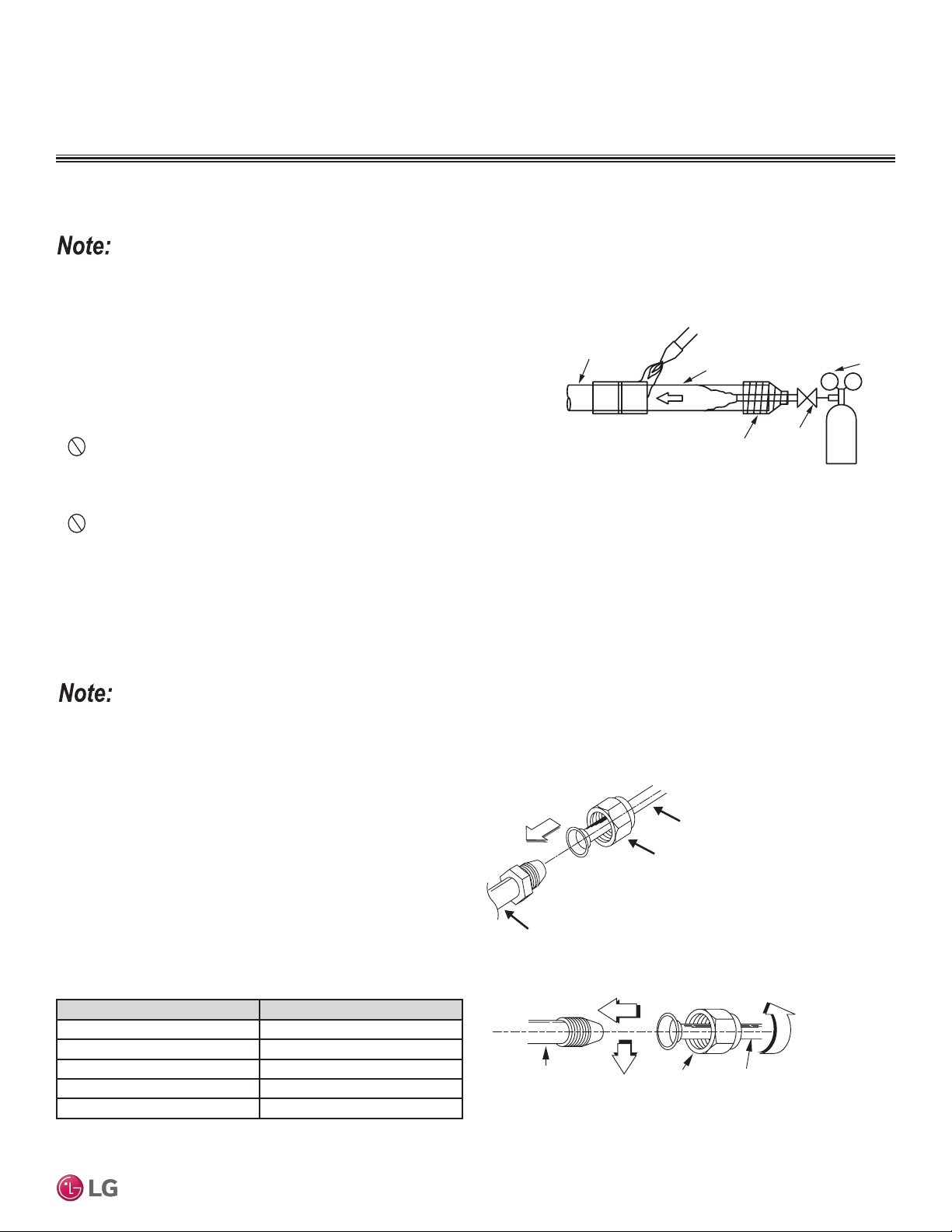
Figure 59: Refrigerant Pipe Brazing.
Keep the piping system free of contaminants and debris such copper burrs, slag, or carbon dust during installation.
Flare Connection Practices
1. Place a couple of drops of refrigerant oil on the opening rim
of the flare before assembling. Take care not to add any
contaminants.
2. Align the center of the refrigerant pipe and corresponding
connection and tighten the flare nut by hand.
3. Following the guidelines as outlined in Table 44 for the amount of
torque to use, tighten the flare nut with a torque wrench until the
wrench clicks.
4. When flare is sufficiently tightened and the system has been
tested for refrigerant leaks, wrap insulation around the
connection.
Indoor Unit
Piping
Field-Supplied
Piping
Flare Nut
Piping O.D. (in.) Torque (lbs. / ft.)
1/4 13-18
3/8 24.6-30.4
1/2 39.8-47.7
5/8 45.6-59.3
3/4 71.6-87.5
Indoor Unit Piping
Flare Nut
Field-Supplied
Piping
Figure 60: Flare Connection, Isometric View.
Figure 61: Flare Connection, Side View.
Table 44: Torque Wrench Tightening.
• Improperly installed flare connections can lead to refrigerant leaks.
• When tightening the flare unit with a torque wrench, ensure the direction for tightening follows the arrow on the wrench.
Loading ...
Loading ...
Loading ...