Loading ...
Loading ...
Loading ...
Due to our policy of continuous product innovation, some specications may change without notication.
©LG Electronics U.S.A., Inc., Englewood Cliffs, NJ. All rights reserved. “LG” is a registered trademark of LG Corp.
68 | DUCTED
Ceiling-Concealed Ducted System Engineering Manual
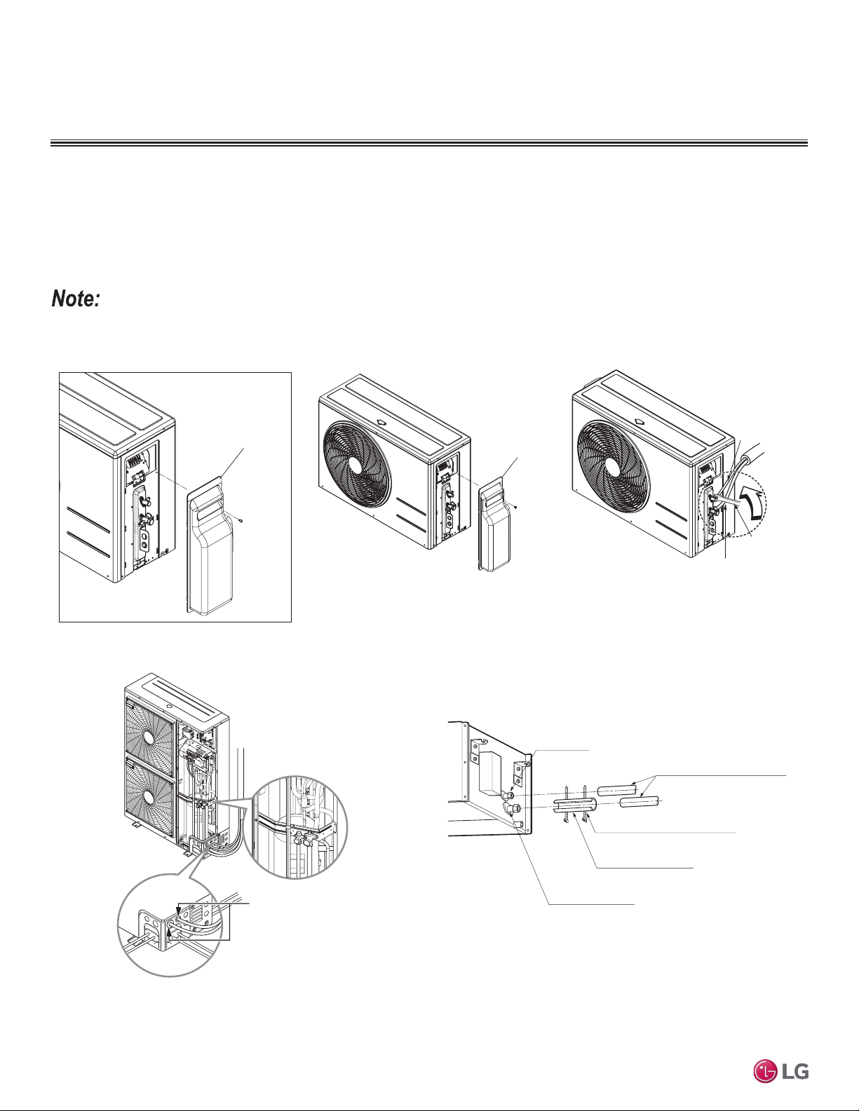
REFRIGERANT PIPING DESIGN
Refrigerant Piping System Layout
Piping can be installed
in one of four different
layouts.
Single Zone Ducted Outdoor Unit Connections
1. Remove the connection cover from the unit by loosening the screws.
2. Align the center of the refrigerant pipe and corresponding connection.
3. Place a couple of drops of refrigerant oil on the opening rim of the flare before assembling. Ensure you do not add any contaminants.
Tighten the flare nut initially by hand.
4. Finish tightening the flare nut with a torque wrench until the wrench clicks. See page 69 for torque information.
Figure 54: Removing the Refrigerant Piping
Connection Cover (LUU097HV, LUU127HV).
Figure 55: Removing the Refrigerant Piping
Connection Cover (LUU247HV).
Figure 56: LUU097HV, LUU127HV, LUU247HV
Refrigerant Piping Connections.
Outdoor unit
Gas side piping
(Bigger diameter)
Liquid side piping
(Smaller diameter)
Torque wrench
Connection cover
When tightening the are nut with a torque wrench, ensure the direction for tightening follows the arrow on the wrench.
Tubing cover
Figure 58: LUU367HV Refrigerant Piping Connections.
Figure 57: Ceiling-Concealed Ducted Refrigerant Piping Connections.
Liquid Piping
Connection
Insulation for Refrigerant Piping
(Field-Supplied)
Vapor Piping Connection
Insulation
(Field-Supplied)
Clamp for Insulation
(Field-Supplied)
Ensure no gaps are present.
Overlap the Insulation at the
Connection
Insulation for Refrigerant Piping
(Field-Supplied)
Insulation for Field-Installed Piping
(Field-Supplied)
Single Zone Ducted Indoor Unit
Connections
Loading ...
Loading ...
Loading ...