Loading ...
Loading ...
Loading ...
Due to our policy of continuous product innovation, some specications may change without notication.
©LG Electronics U.S.A., Inc., Englewood Cliffs, NJ. All rights reserved. “LG” is a registered trademark of LG Corp.
54 | DUCTED
Ceiling-Concealed Ducted System Engineering Manual
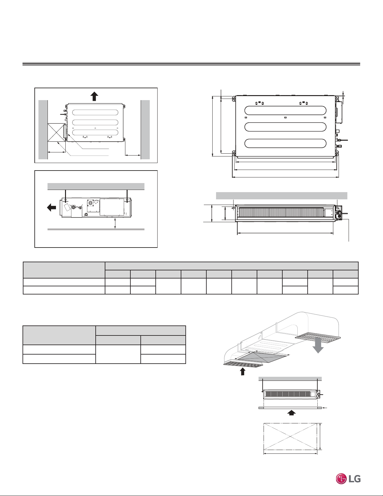
Figure 29: Low Static Ducted Indoor Unit General Service Space Required Dimensions and Bolt Locations
Figure 30: Low Static Ducted Indoor Unit Access Panel Required
Dimensions.
Table 31: Low Static Ducted Indoor Unit Bolt Location Dimensions.
Indoor Unit
PLACEMENT CONSIDERATIONS
C
E
G
D
F
I
A
J
B
H
Drainage hole
Model / Capacity (Btu/h)
Dimensions (in.)
A B
LDN097HV4 / 9,000
31-1/2
31-1/2
LDN127HV4 / 12,000 39-3/8
Access Opening
(
23-5/8
x
23-5/8
)
Control box
H = ≤25/32
• "H" dimension is necessary to ensure a slope is included for
condensate drainage.
Side view
23-5/8
23-5/8
(Unit : Inch)
(Unit : Inch)
Top view
A (Min)
Ceiling
Service Space
A
B
B (Min)
Model / Capacity (Btu/h)
Dimensions (in.)
A B C D E F G H I J
LDN097HV4 / 9,000 28-27/32 30-13/32
24-23/32 27-9/16 1-13/32 7-15/32 25/32
25-31/32
6-3/32
27-9/16
LDN127HV4 / 12,000 36-23/32 38-9/32 33-27/32 35-7/16
Table 32: Low Static Ducted Indoor Unit Access Panel Required
Dimensions.
Loading ...
Loading ...
Loading ...