Loading ...
Loading ...
Loading ...
Due to our policy of continuous product innovation, some specications may change without notication.
©LG Electronics U.S.A., Inc., Englewood Cliffs, NJ. All rights reserved. “LG” is a registered trademark of LG Corp.
DUCTED | 63
Refrigerant Piping Design and Best Practices
Device Connection Limitations
A single-zone ceiling-concealed ducted system consists of one outdoor unit and one indoor unit. One of the most critical elements of a sin-
gle-zone ceiling-concealed ducted system is the refrigerant piping. The table below lists pipe length limits that must be followed in the design
of a single-zone ceiling-concealed ducted refrigerant pipe system:
REFRIGERANT PIPING DESIGN
Design Guideline Summary
Table 38: Single-Zone Ceiling-Concealed Ducted Refrigerant Piping System Limitations.
System Model Name
LD097HV4, LD127HV4 LH247HV LH367HV
Pipe Length
(ELF = Equivalent Length of Pipe)
Longest total equivalent piping
length
66 feet 164 feet 246 feet
Shortest total equivalent
piping length
6.6 6.6 6.6
Distance between ttings and
indoor or outdoor units
≥20 inches ≥20 inches ≥20 inches
No additional refrigerant
25 feet 25 feet 25 feet
Elevation
(All Elevation Limitations are
Measured in Actual Feet)
If outdoor unit is above indoor
unit
49 feet 98 feet 98 feet
If outdoor unit is below indoor
unit
49 feet 98 feet 98 feet
Additional Refrigerant Needed (oz/ft)
0.22 0.43 0.43
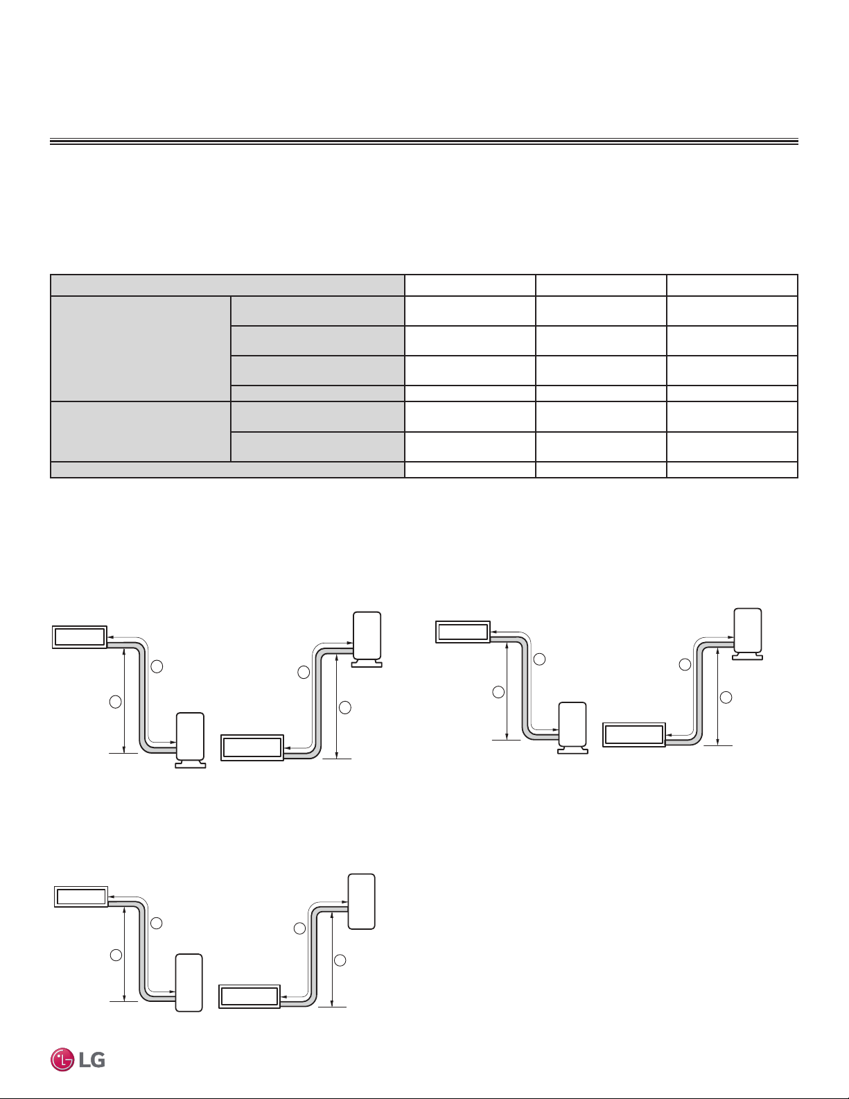
DFS System Layout
Figure 43: Typical LD097HV4 and LD127HV4 System Layout. Figure 44: Typical LH247HV System Layout.
Outdoor unit
Indoor unit
A
B
Outdoor unit
Indoor unit
A
B
98
98
164
Max Length = A
Max Elevation = B
164
Unit = Feet
Outdoor unit
Indoor unit
A
B
Outdoor unit
Indoor unit
A
B
98
98
246
Max Length = A
Max Elevation = B
246
Unit = Feet
Figure 45: Typical LH367HV System Layout.
Outdoor unit
Indoor unit
A
B
Outdoor unit
Indoor unit
A
B
49
49
66
Max Length = A
Max Elevation = B
66
Unit = Feet
Loading ...
Loading ...
Loading ...