
To reduce the risk of injury, the user must read and understand the Operator’s
Manual before using this product. Save these instructions for future reference.

2
TABLE OF CONTENTS
1. SAFETY INFORMATION
1.1 Operating Safety
1.2 Roller Safety
1.3 Engine Safety
1.4 Fuel Safety
1.5 Transporting Safety
1.6 Environmental Safety/Decommissioning
1.7 Emissions Information
1.8 Emission Control Label
2. TECHNICAL PERFORMANCE
3. SPECIFICATIONS
3.1 Roller Compactor Parts
3.2 Unpacking the Unit
4. INSPECTION
4.1 Engine Initial Servicing
4.2 Cable Assembly
5. BEFORE STARTING
5.1 Engine Oil Check
5.2 Fuel Level Check
5.3 V-Belt Inspection
5.4 V-Belt Tension
5.5 Vibrator Oil Check
5.6 Handle Bar Adjustment
6. STARTUP
6.1 Starting The Engine
7. OPERATION
7.1 Operating the Compactor
7.2 Shutting Down the Compactor
7.3 Emergency Shutdown
8. UPKEEP
8.1 Engine Air Cleaner
8.2 Engine Oil
8.3 Spark Plug
8.4 V-Belt Inspection
8.5 Park Arrester Cleaning
8.6 Tightening Torque
8.7 Machine Inspection
9. STORAGE
10. REPLACEMENT PARTS
11. TROUBLESHOOTING
12. MAINTENANCE RECORD
13. EQUIPMENT WARRANTY
14. SERVICE CENTERS
15. PARTS MANUAL
4
5
6
6
7
8
8
9
9
9
9
11
12
12
12
12
13
13
13
14
14
14
15
15
16
16
16
16
16
16
16
17
17
18
18
18
19
19
19
22
23
23
23
27
3
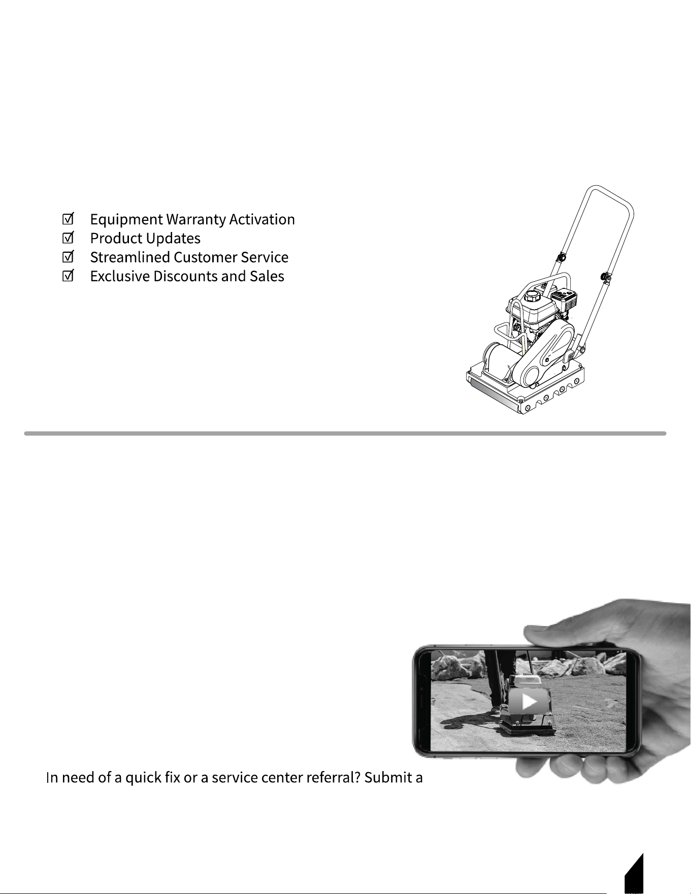
Register Your Equipment
Thank you for purchasing TOMAHAWK equipment! Your product is covered by the
TOMAHAWK Warranty policy, but in order to activate your warranty, we need you to register
your product. In addition to activating your equipment warranty, product registration will
grant you access to important product updates, streamlined customer service and more.
INCLUDED WITH YOUR REGISTRATION
STEPS TO REGISTER YOUR EQUIPMENT
1. Visit www.tomahawk-power.com
2. Choose “Product Registration” at the bottom of the page
3. Enter your equipment’s serial number to get started
4. Provide all required information
5. Submit Registration
Equipment Resources
Tomahawk Customer Service doesn’t stop at checkout. We understand to keep a job-site
running smoothly - the proper equipment, spare parts, instruction manuals, and more are
needed at the drop of a hat. Visit www.tomahawk-power.com to gain access to the incredible
resources below.
How To Video Library
More of a visual person? Visit our Video Library for equipment
assembly instructions, troubleshooting tips, and more!
Found on each product listing or the Service Videos Page
Manual and Assembly Guide Library
Visit our Manual Library if you are looking for a lost
operations manual or a particular spare part?
Found on each product listing or the Tomahawk Manuals Page
Service Requests
Service Request and a Tomahawk Technician will respond
shortly to get you the help you need.
Choose “Service Request” at the bottom of www.tomahawk-power.com

4
This manual provides information and procedures to safely operate and maintain this
equipment. For your own safety and protection from injury, carefully read, understand, and
observe the safety instructions described in this manual.
Keep this manual or a copy of it with the equipment. If you lose this manual or need an
additional copy, please contact Tomahawk Power, LLC or visit
www.tomahawk-power.com
This equipment is built with user safety in mind; however, it can present hazards if
improperly operated or serviced. Follow operating instructions carefully. If you have
questions about operating or servicing this equipment, contact TOMAHAWK®.
The information contained in this manual is based on equipment’s production at the time of
publication. TOMAHAWK® reserves the right to change any portion of this information
without notice.
No part of this publication may be reproduced in any form or by any means,
from TOMAHAWK®.
Any type of reproduction or distribution not authorized by TOMAHAWK® represents an
make technical modifications, even without due notice, which aim at improving our
machines or their safety standards.
1. SAFETY INFORMATION
This manual contains DANGER, WARNING, CAUTION, and NOTE callouts which must be
followed to reduce the possibility of personal injury, damage to the equipment,
or improper service.
This is the safety alert symbol. It is used to alert you to potential personal injury
hazards. Obey all safety messages that follow this symbol to avoid possible injury
or death.
DANGER indicates an imminently hazardous situation which, if not avoided, will
result in death or serious injury.
WARNING indicates a potentially hazardous situation which, if not avoided, could
result in death or serious injury.
CAUTION indicates a potentially hazardous situation which, if not avoided, may
result in minor or moderate injury.
DANGER
WARNING
CAUTION

5
1.1 Operating Safety
Familiarity and proper training are required for the safe operation of equipment!
Equipment operated improperly or by untrained personnel can be dangerous! Read the
operating instructions contained in both this manual and the engine manual and
operators should receive instruction from someone familiar with the equipment before
being allowed to operate the machine.
1.1.1 NEVER allow anyone to operate this equipment without proper training. People
operating this equipment must be familiar with the risks and hazards associated with it.
1.1.2 ALWAYS be safety-conscious by dressing appropriately during operation. Always
wear protective footwear, safety glasses/eyeware, and a hard hat.
1.1.3 NEVER operate this equipment when not feeling well due to fatigue, illness or when
under medication.
1.1.4 NEVER operate this equipment under the influence of drugs or alcohol.
1.1.5 ALWAYS check the equipment for loosened threads or bolts before starting.
1.1.6 DO NOT use the equipment for any purpose other than its intended purposes
or applications.
1.1.7 ALWAYS clear the work area of any debris, tools, etc. that would constitute a hazard
while the equipment is in operation.
1.1.8 ALWAYS use only the accessories or attachments recommended by the Tomahawk
Power for this equipment. Using unapproved accessories or attachments can result in
damage to the equipment and/or injury to the user.
1.1.9 ALWAYS
1.1.10 ALWAYS know the location of the nearest first aid kit.
1.1.11 NEVER use accessories or attachments that are not recommended by
Tomahawk Power. Damage to equipment and injury to the user may result.
1.1.12 NEVER leave machine running unattended.
1.1.13 ALWAYS be sure operator is familiar with proper safety precautions and operation
techniques before using machine.
1.1.14 ONLY trained and qualified personnel 18 years of age and older should operate this
machinery.
1.1.15 DO NOT add fuel to equipment if it is placed inside truck bed with plastic liner.
NOTE: Whenever necessary, replace nameplate, operation and safety decals when they
6
1.2 Roller Safety
1.2.1 ALWAYS keep the machine in proper running condition.
1.2.2 ALWAYS store equipment properly when it is not being used. Equipment should be
stored in a clean, dry location out of the reach of children and unauthorized personnel.
1.2.3 NEVER lubricate components or attempt service on a running machine.
1.3 Engine Safety
1.3.1 NEVER run engine without an air filter or with a dirty air filter. Severe engine damage
may occur. Service air filter frequently to prevent engine malfunction.
1.3.2 NEVER tamper with the factory settings of the engine or engine governor. Damage
to the engine or equipment can result if operating in speed ranges above the
1.3.3 NEVER
WARNING Never disconnect any emergency or safety devices, as they are
intended for operator safety. Disconnecting these devices can cause severe
injury, bodily harm, or even death, and will void all warranties.
DANGER
resulting in severe bodily harm or even death.
WARNING
DANGER
DANGER
DANGER
DANGER
DANGER The engine of this equipment requires an adequate free flow of
cooling air. NEVER operate this equipment in any enclosed or narrow area
where free fl ow of the air is restricted. If the air fl ow is restricted it will cause
injury to people and property and serious damage to the equipment or engine.
7
1.3.4 DO NOT place hands or fingers inside engine compartment when engine is running.
1.3.5 NEVER operate the engine with heat shields or guards removed.
1.3.6 DO NOT remove the radiator cap while the engine is hot. High pressure boiling water
will gush out of the radiator and severely scald any persons in the general area of
the compactor.
1.3.7 DO NOT remove the coolant drain plug while the engine is hot. Hot coolant will
gush out of the coolant tank and severely scald any persons in the general area of
the compactor.
1.3.8 DO NOT remove the engine oil drain plug while the engine is hot. Hot oil will gush
out of the oil tank and severely scald any persons in the general area of the compactor.
NOTE:
1.4 Fuel Safety
1.4.1 DO NOT add fuel to the equipment if it is placed inside a truck bed with a plastic liner,
1.4.2 DO NOT start the engine near spilled fuel or combustible fluids, as diesel fuel is
1.4.3 ALWAYS refuel in a well-ventilated area, away from sparks and open flames.
1.4.4 ALWAYS
1.4.5 DO NOT fill the fuel tank while the engine is running or hot.
1.4.6 DO NOT overfill the tank, as spilled fuel could ignite if it comes into contact with hot
engine parts or sparks from the ignition system.
NOTE: Store fuel in appropriate containers, in well-ventilated areas, and away from sparks
and flames.
1.4.7 NEVER use fuel as a cleaning agent.
1.4.8 DO NOT
fuel vapors or if fuel is spilled on a hot engine.
WARNING
Allow these parts to cool before servicing equipment.
CAUTION Always disconnect the NEGATIVE battery terminal before
performing service on the equipment.
WARNING
CAUTION
8
1.5 Transporting Safety
1.5.1 NEVER allow any person or animal to stand underneath the equipment while it is
NOTE:
damaged, and that screws are neither loose nor missing.
1.5.2 ALWAYS
of the equipment.
1.5.3 ALWAYS shut down the engine before transporting.
1.5.4 NEVER
1.5.5 ALWAYS Tighten the fuel tank cap securely and close the fuel cock to prevent fuel
from spilling.
1.5.6 ALWAYS
1.5.7 ALWAYS
1.5.8 DO NOT
1.5.9 ALWAYS tie down the equipment during transport by securing it with rope.
1.6 Environmental Safety/Decommissioning
Decommissioning is a controlled process used to safely retire a piece of equipment that is
no longer serviceable. If the equipment poses an unacceptable and unrepairable safety risk
follow the rules below:
• DO NOT pour waste or oil directly onto the ground, down a drain, or into any water source.
• Contact your country's Department of Public Works or recycling agency to arrange for
the proper disposal of any electrical components, waste, or oil associated with this
equipment.
• When the life cycle of this equipment is over, remove the battery and take it to an
appropriate facility for lead reclamation. Use safety precautions when handling
batteries that contain sulfuric acid.
CAUTION Always keep battery cables in good working condition.
Repair or replace all worn cables.
CAUTION

• When the life cycle of this equipment is over, it is recommended that the trowel frame
and all other metal parts be sent to a recycling center. Metal recycling involves collecting
metal from discarded products and transforming it into raw materials for manufacturing
new products. Recyclers and manufacturers promote metal recycling because it helps
save on energy costs.
1.7 Emissions Information
The diesel engine used in this equipment is designed to reduce harmful levels of carbon
emissions. This engine has been certified to meet US EPA evaporative emissions
requirements in its installed configuration.
Attempting to modify or adjust the engine emission system by unauthorized personnel
without proper training can damage the equipment or create an unsafe condition.
resulting in fines or other penalties.
1.8 Emission Control Label
The emission control label is an integral part of the emission system and is strictly
regulated. The label must remain with the engine for its entire life. If a replacement
emission label is needed, please contact your authorized Honda Engine Distributor.
2. TECHNICAL PERFORMANCE
powered by the industry-leading Honda GX160 engine. Built for professionals who demand
force in a compact, easy-to-maneuver design, perfect for tight spaces and small job sites.
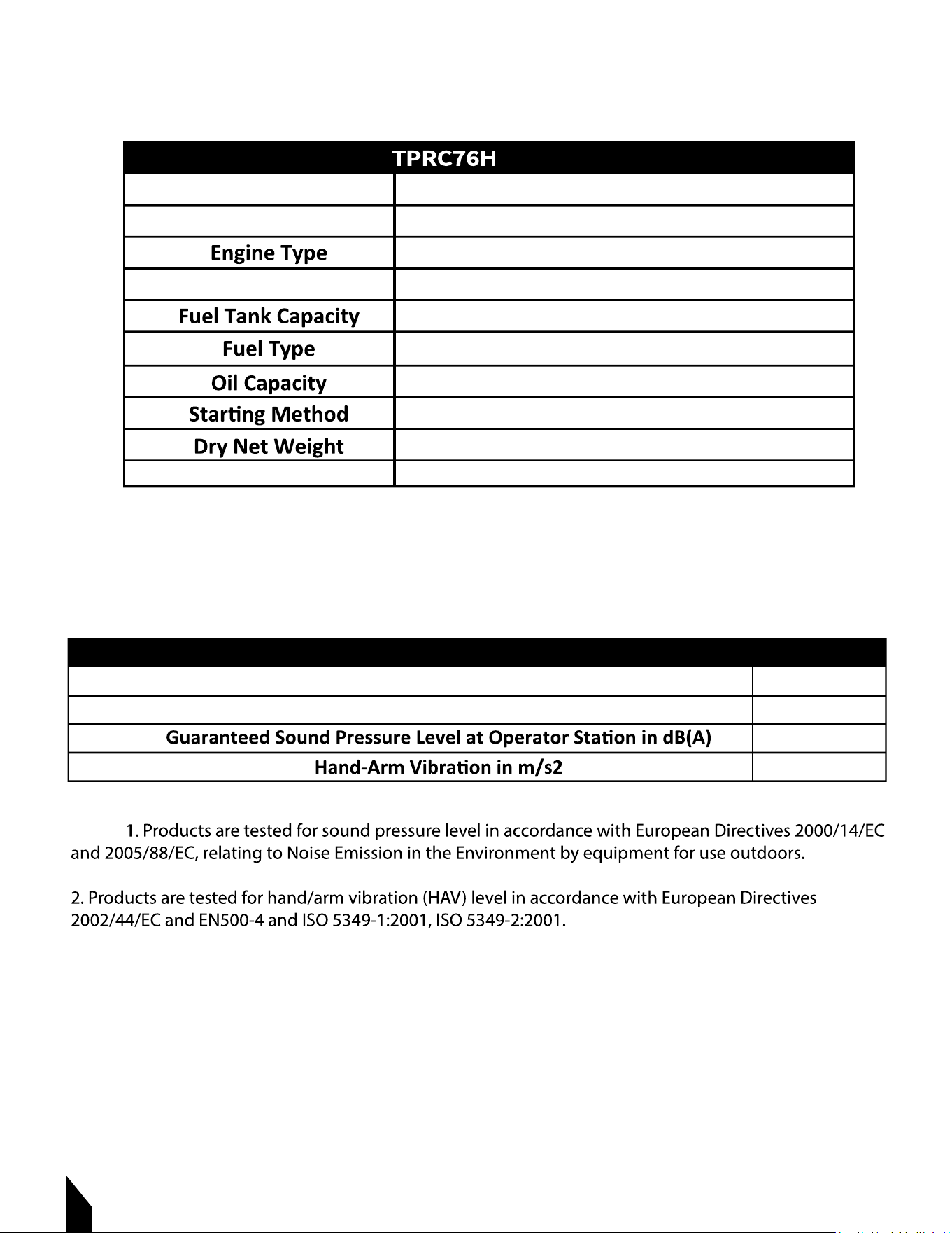
3. SPECIFICATIONS
9
No. of Rubber Rolls
Centrifugal Force
Plate Size (W x L)
Vibrator Oil Volume
4
2,270.57 lbf (10.1 kN)
5,400 vpm (90 Hz)
12.60 x 17.05 in (320 x 433 mm)
0.15 quart (140 cc)
198.42 lbs. (90 kg.)
ROLLER COMPACTOR
10
ENGINE
Engine
Engine Model
Max Power
Dimensions
HONDA
GX160
Air-cooled 4 cycle Gasoline Engine
5.0 HP (4.1 kW) @ 3600 RPM
Approx. 0.53 gallons (2.0 liters)
Unleaded Gasoline
0.15 gallons (0.56 liters)
Recoil Start
35 lbs (16 Kg.)
12.0 x 13.6 x 13.0 in. (305 x 346 x 329 mm)
TRC17H NOISE AND VIBRATION EMISSIONS
Measured Sound Power Level in dB(A)
Guaranteed Sound Power Level in dB(A)
104
105
95
8.2
NOTE:
11
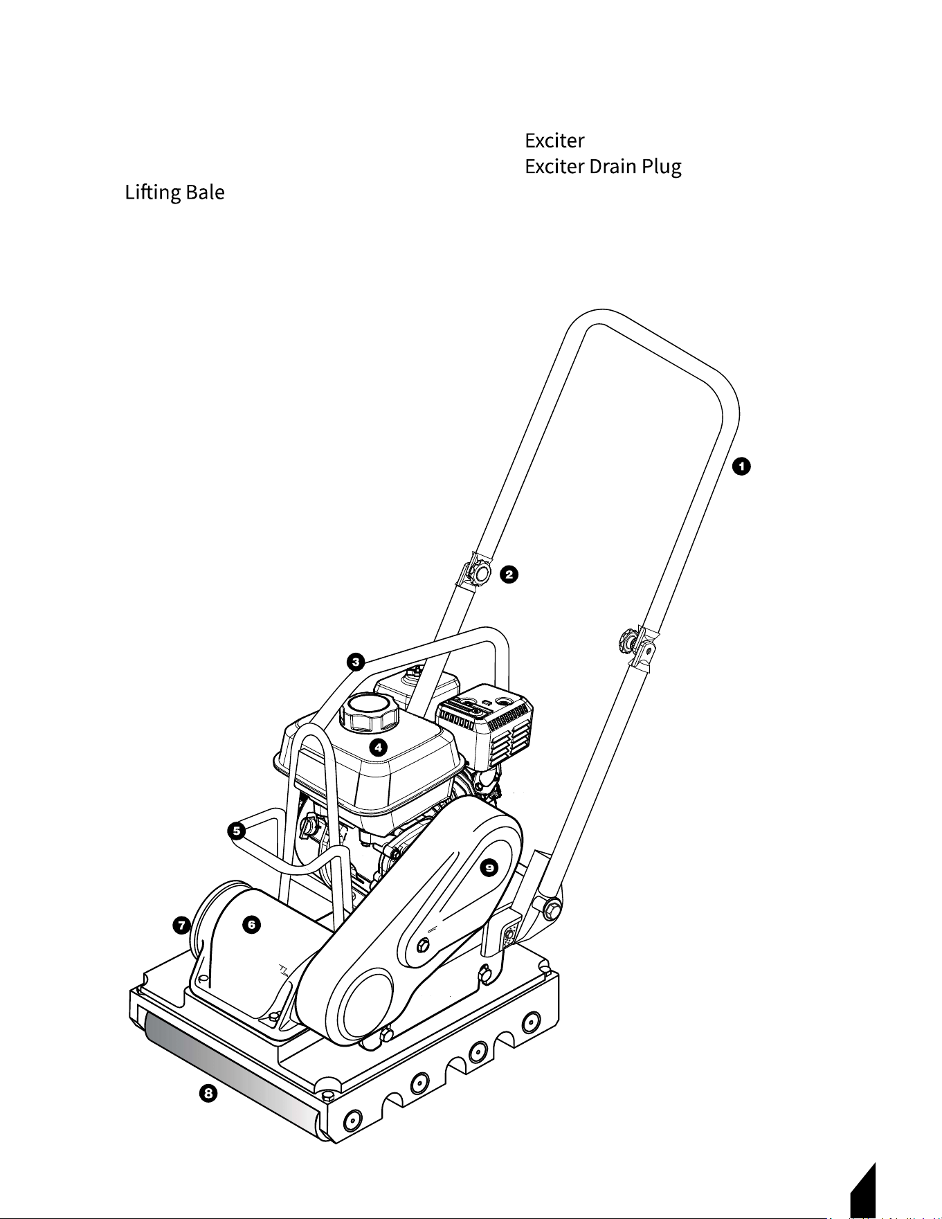
3.1 Roller Compactor Parts
1. Handle Bar
2. Handle Bar Adjuster Bolt
3.
4. Engine
5. Hand Grip
6.
7.
8. Rubber Rollers
9. Belt Cover
12
3.2 Unpacking the Unit
you have inspected all parts and successfully operated the machine. Do not discard this
operations manual.
If any parts are missing or damaged, please contact TOMAHAWK® customer support by
4. INSPECTION
4.1 Engine Initial Servicing
4.1.1 The engine must be checked for proper lubrication and filled with fuel prior to
operation. Refer to the manufacturer's engine manual for detailed instructions on
operation and servicing.
• Throttle Lever: Used to adjust engine RPM speed. For normal operation, this lever
should always be placed in the RUN position.
• Fuel Cap: Remove this cap to add unleaded gasoline to the fuel tank.
Fill with unleaded gasoline.
• Fuel Tank: Refer to Engine Table for fuel tank capacity. Ensure the cap is tightened
securely.
NOTE: DO NOT overfill. For additional information, refer to the Honda engine
owner's manual.
5. BEFORE STARTING
5.1 Read all safety instructions at the beginning of the manual.
5.2 Clean the compactor, removing dirt and dust, particularly from the engine cooling
air inlet, carburetor, and air cleaner.
5.3 Check the air filter for dirt and dust. If the air filter is dirty, replace it with a new one
as required.
5.4
Check fastening nuts and bolts for tightness.
DANGER
DANGER Add fuel to the tank only when the engine is stopped and has had
an opportunity to cool down. In the event of a fuel spill, DO NOT attempt
to start the engine until the fuel residue has been completely wiped up
and the area surrounding the
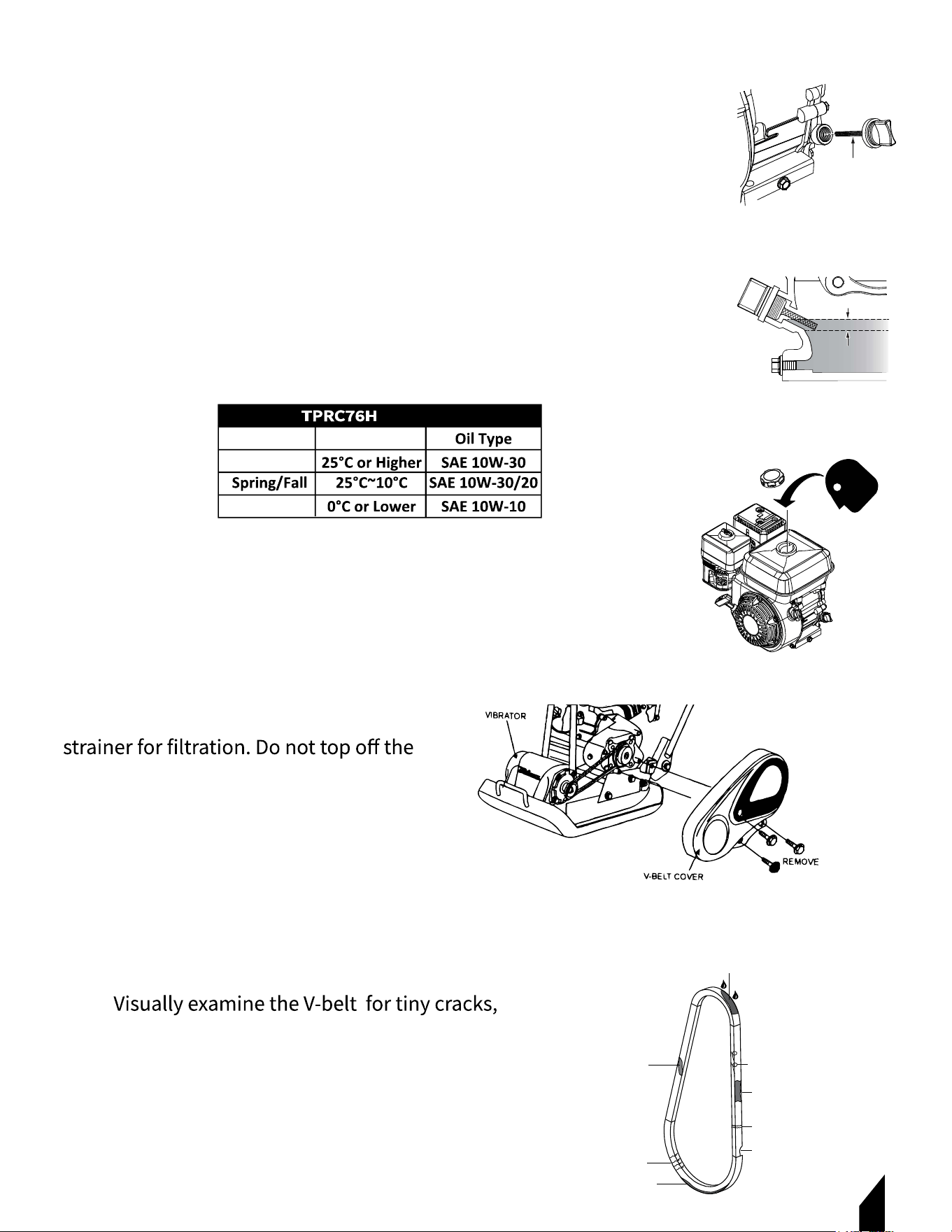
5.1 Engine Oil Check
5.1.1 To check the engine oil level, place the compactor on
secure, level ground with the engine stopped.
5.1.2 Remove the dipstick from the engine oil filler hole and
wipe it clean. FIGURE 1.
5.1.3 Insert and remove the dipstick without screwing it into
the filler neck. Check the oil level shown on the dipstick.
5.1.4 If the oil level is low , fill to the edge of the oil filler hole
with the recommended oil type as listed in Oil Type Table.
Figure 2.
5.2 Fuel Level Check
5.2.1 Visually inspect the fuel level. If it is
low, replenish with unleaded fuel.
FIGURE 3.
5.2.2 When refueling, be sure to use a
fuel. Wipe up any spilled fuel
immediately.
5.3 V-Belt Cover Removal
To inspect the V-belt, remove the bolts
securing the belt cover to the frame as shown in
FIGURE 4.
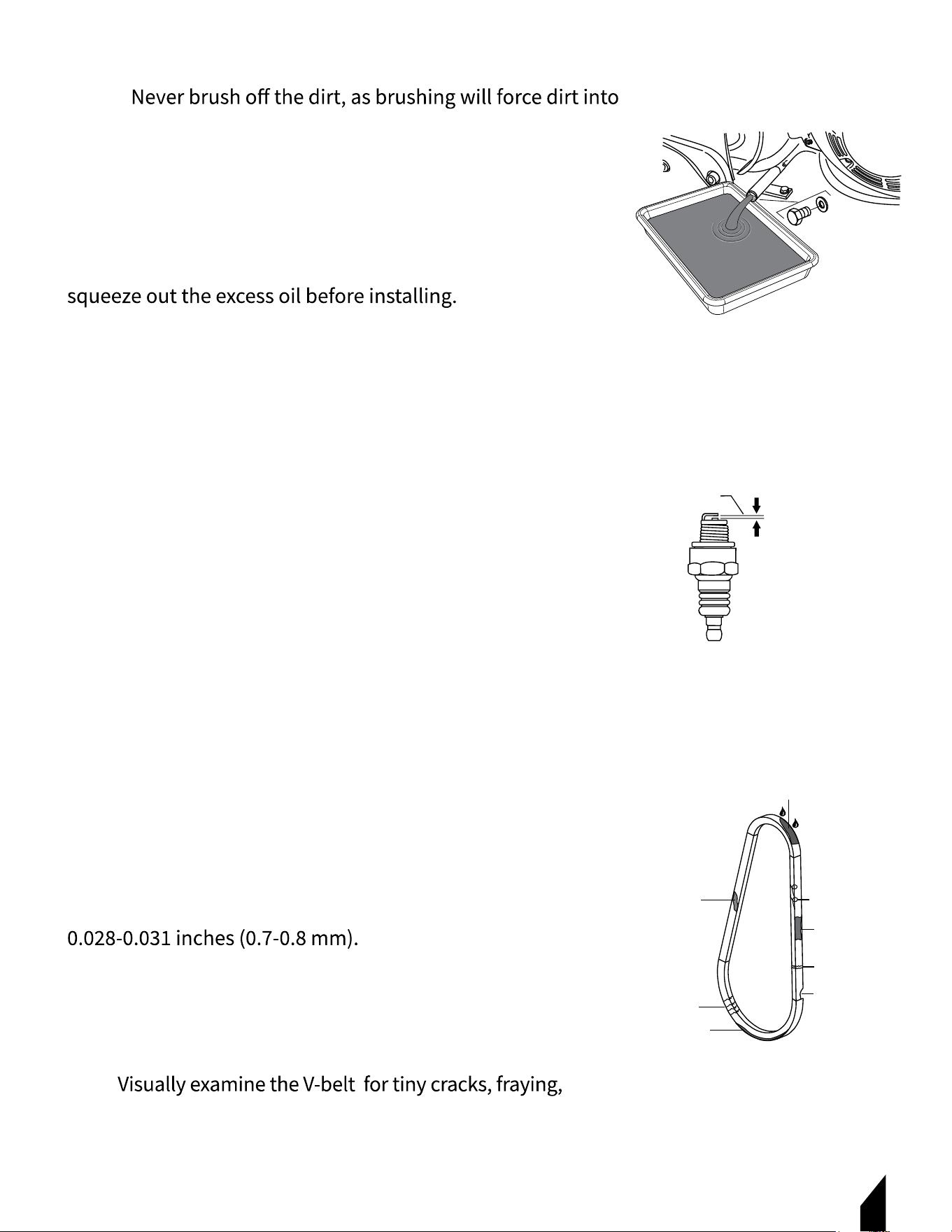
5.4 V-Belt Inspection
5.4.1
fraying, missing pieces of rubber, peeling, or other
damage. FIGURE 5.
13
FIGURE 1
FIGURE 5
FIGURE 2
FIGURE 3
FIGURE 4
DIPSTICK
UPPER LIMIT
LOWER LIMIT
FUEL
CAP
GLAZED
OIL SOAKED
BROKEN
CORD FAILURE
CRACKS
MISSING RUBBER
SIDEWALL
WEAR
WORN BACK
COVER
OIL TYPE
Season
Summer
Winter
Temperature
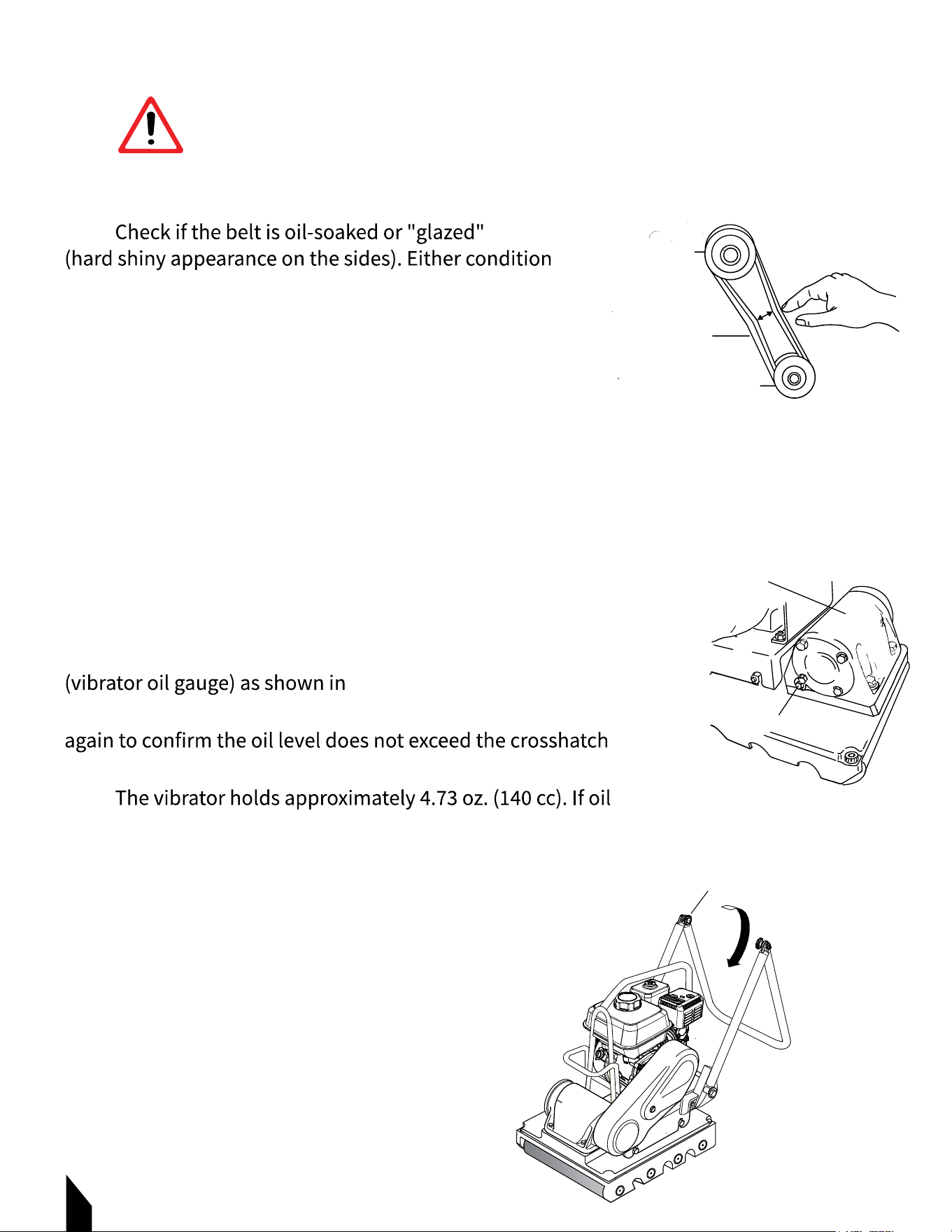
5.4.2
can cause the belt to run hot, weakening it and increasing
the risk of breaking. If the V-belt shows any of these wear
conditions, replace it immediately.
5.5 V-Belt Tension
The V-belt tension is proper if it bends 10 to 15 mm when
depressed with a finger at the midpoint between the clutch
and vibrator pulleys. FIGURE 6.
5.6 Vibrator Oil Check
5.6.1 Place the plate compactor horizontally on a flat surface.
5.6.2 Ensure the compactor is level when checking the oil in
the vibrator assembly.
5.6.3 Check the vibrator oil level by removing the oil plug
FIGURE 7.
5.6.4 Clean the oil gauge, re-thread it back in, then remove it
marks on the oil plug. Do not overfill!
5.6.5
is required, use only SAE 10W-30 motor oil.
5.7 Handle Bar Adjustment
5.7.1 Loosen the handle bar bolts.
5.7.2 Adjust the handle bar to the desired position.
5.7.3 When the handle bar is at the desired height,
tighten the bolts. FIGURE 8.
14
FIGURE 6
FIGURE 7
FIGURE 8
DANGER
DANGER EXPLOSIVE FUEL!
Motor fuels are highly flammable and can be dangerous if mishandled.
DO NOT smoke while refueling. DO NOT attempt to refuel the compactor
if the engine is hot or running.
VIBRATOR
DRAIN PLUG
CLUTCH
PULLEY
CORRECT V-BELT
TENSION 10-15 MM
WHEN DEPRESSED
AS SHOWN.
V-BELT
PULLEY
VIBRATOR
FOLD
POSITION
BOLT
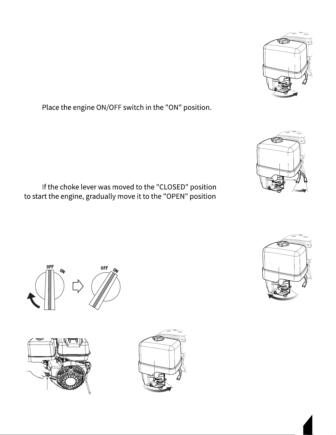
6. STARTUP
6.1 Starting The Engine
6.1.1 Place the engine fuel valve lever in the “ON” position.
FIGURE 9.
6.1.2 Move the throttle lever to the idle position. FIGURE 10.
6.1.3 Place the choke lever in the “CLOSED” position if
starting a cold engine. FIGURE 11.
6.1.4
FIGURE 12.
6.1.5 Grasp the starter grip and slowly pull it out until you feel
strong resistance, which indicates the compression point.
Rewind the rope slightly from that point and then pull it out
sharply. FIGURE 13.
6.1.6 When the engine starts, release the starter grip and
allow the rope to recoil.
6.1.7
as the engine warms up. If the engine has not started, repeat
steps 1 through 6. FIGURE 14.
6.1.8 Before placing the compactor into operation, run the
engine for several minutes. Check for fuel leaks and any
unusual noises that might indicate a loose component.
15
LEVER
ON
FUEL VALVE
OFF
THROTTLE
LEVER
RUN IDLE
OPEN
CLOSE
CHOKE LEVER
STARTER GRIP
OPEN
CLOSE
CHOKE LEVER
FIGURE 9
FIGURE 10
FIGURE 11
FIGURE 12
FIGURE 13 FIGURE 14
16
7. OPERATION
7.1 Operating the Compactor
7.1.1 Once the engine has started, quickly move the engine
throttle lever to the run position. FIGURE 15.
7.1.2 Push and pull the handlebar to move the compactor
forward and backward and flatten the interlocking block.
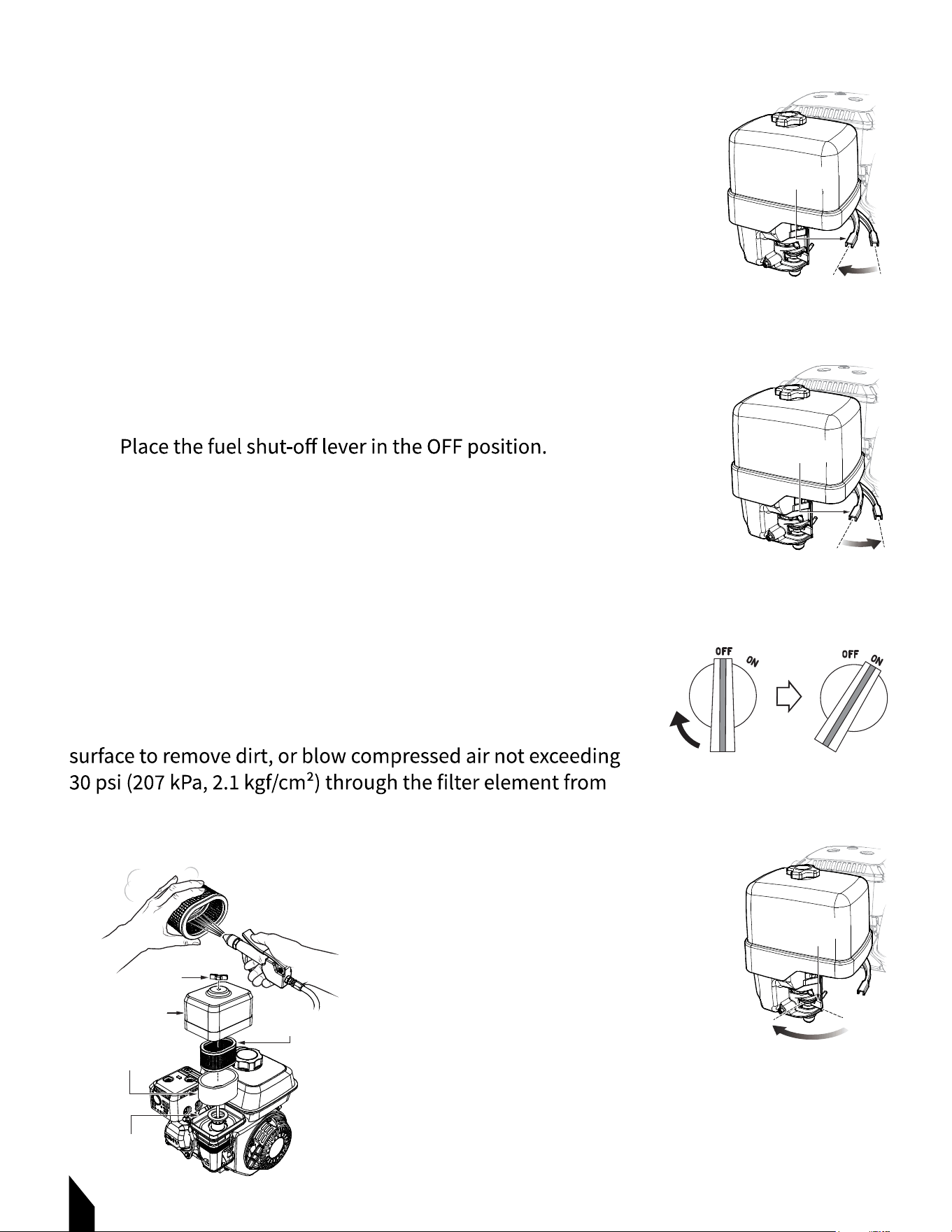
7.2 Shutting Down the Compactor
7.2.1 Move the throttle lever to the idle position and run the
engine for three minutes at low speed. FIGURE 16.
7.2.2 Place the engine ON/OFF switch in the OFF position.
FIGURE 17.
7.2.3
FIGURE 18.
7.3 Emergency Shutdown
7.3.1 Move the throttle lever quickly to the IDLE position.
7.3.2 Place the engine ON/OFF switch in the OFF position
8. Upkeep
8.1 Engine Air Cleaner
8.1.1 Remove the air cleaner cover and foam filter element.
8.1.2 Tap the paper filter element several times on a hard
the inside out.
FIGURE 15
FIGURE 16
FIGURE 17
FIGURE 18
FIGURE 19
THROTTLE
LEVER
RUN
IDLE
THROTTLE
LEVER
RUN
IDLE
LEVER
ON
FUEL VALVE
OFF
AIR CLEANER
COVER
ELEMENT
BLOW COMPRESSED
PAPER FILTER
AIR FROM THE
INSIDE OUT
ELEMENT
FOAM FILTER
GASKET
WING NUT
17
NOTE:
the fibers. Replace the filter element if very dirty.
8.1.3 Clean the foam element in warm, soapy water
or a nonflammable solvent.
8.1.4 Rinse and dry thoroughly.
8.1.5 Dip the element in clean engine oil and completely
8.1.6 Blow compressed air through the air cleaner
cover as shown in FIGURE 19.
8.1.7 Clean the inside of the air filter cover with warm,
soapy water or a nonflammable solvent.
8.1.8 Rinse and dry thoroughly.
8.2 Engine Oil
8.2.1 Remove the oil drain bolt and sealing washer, and
allow the oil to drain into a suitable container. FIGURE 20.
8.2.2 Replace the engine oil with the recommended type
as listed in Table 5. For engine oil capacity, see Engine
Specifications. Do not overfill.
8.2.3 Reinstall the drain bolt with the sealing washer and
tighten securely.
8.3 Spark Plug
8.3.1 Remove and clean the spark plug with a wire brush if it
is to be reused. FIGURE 21.
8.3.2 Discard the spark plug if the insulator is cracked or
chipped.
8.3.3 Using a feeler gauge, adjust the spark plug gap to
8.3.4 Thread the spark plug into the cylinder hole by hand to
prevent cross-threading, then tighten securely.
8.4 V-Belt Inspection
8.4.1
missing pieces of rubber, peeling, or other damage. FIGURE 22.
FIGURE 20
FIGURE 21
FIGURE 22
DRAIN BOLT
SEALING WASHER
.028 - .031 IN.
(0.7- 0.8 MM.)
GLAZED
OIL SOAKED
BROKEN
CORD FAILURE
CRACKS
MISSING RUBBER
SIDEWALL
WORN BACK
COVER
17
18
8.5 Park Arrester Cleaning
NOTE: Clean the spark arrester every year or 100 hours.
the V-belt immediately.
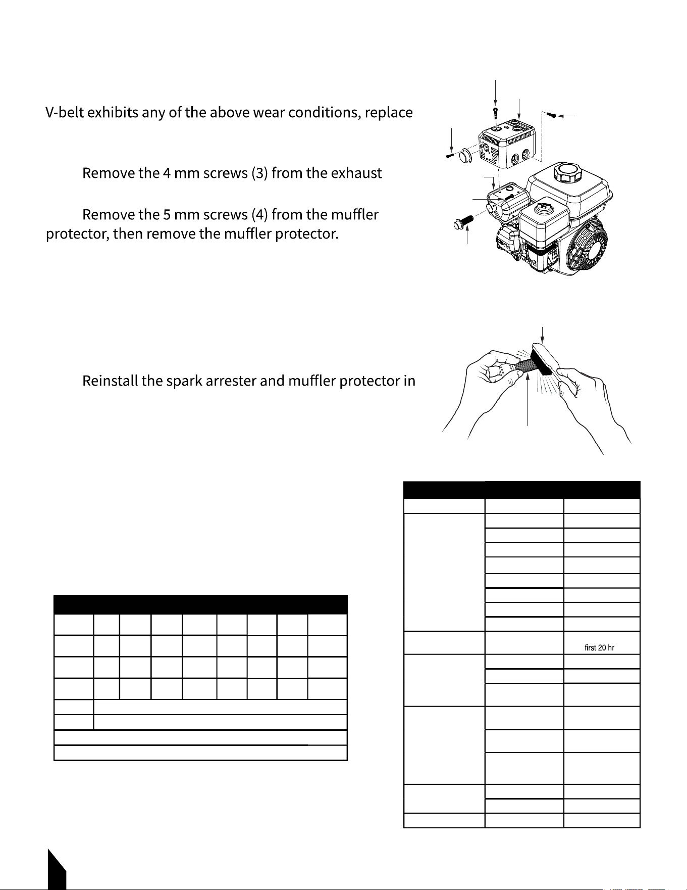
8.5.1
deflector, then remove the deflector. FIGURE 23.
8.5.2
8.5.3 Remove the 4 mm screws from the spark arrester,
then remove the spark arrester.
8.5.4 Carefully remove carbon deposits from the spark
arrester screen with a wire brush. FIGURE 24.
8.5.5 If the spark arrester is damaged and has breaks or
holes, replace it with a new one.
8.5.6
reverse order of disassembly.
8.6 Tightening Torque
Reference the Tightening torque Table.
8.7 Machine Inspection
Reference the Machine inspection Table.
FIGURE 23
FIGURE 24
4 MM
SCREW
5 MM
SCREW
MUFFLER
5 MM
PROTECTOR
SCREW
SPARK
ARRESTER
4 MM
SCREW
WIRE BRUSH
SPARK ARRESTER
SCREEN
Material 6mm 8mm 10mm 12mm
TIGHTENING TORQUE (IN. KG/CM DIAMETER)
20mm14mm 16mm 18mm
4T 70 150 300 500 750 1,100 1,400 2,000
6-8T 100 250 500 800 1,300 2,000 2,700 3,800
11T 150 400 800 1,200 2,000 2,900 4,200 5,600
*
100 (6mm) 300 ~ 350 (8mm) 650 ~ 700 (10mm)
** In case counterpart is of aluminum
Bolt threads used with this machine are all right handed
Material and quality of material is marked on each bolt, and screw.
MACHINE INSPECTION
Interval Check Solution
Machine
Daily Before Starting
Clean if necessary.
Fuel Tank For Leaks Repair fuel leaks.
Fuel System for Leaks Repair fuel leaks.
Engine Oil Add oil if necessary.
Vibrator Oil
Air Cleaner Element
Add oil if necessary.
Clean/Replace
Guard Frame Inspect deformations
Shock Absorber Replace if damaged.
Engine OilEvery 20 Hours
Replace only after
s.
Engine Oil Change
Every 100
Air Cleaner Element Clean/Replace
Vibrator Oil
Every 200 hours
V-Belt
Inspect, replace if
Check oil level. Check
for leaks.
Clutch
damaged or worn.
Engine Bolts
Replace bolts
Inspect, replace if not
working properly.
elongated.
if deformed or
Every 300 hours
Vibrator Oil Change
Fuel Filter Change
Fuel Lines ReplaceEvery 2 years
19
9. STORAGE
9.1
9.2 Cover the machine to prevent dust and dirt buildup.
9.3 Store the machine in a dry area away from direct sunlight.
9.4 Do not leave the machine outdoors. Keep it indoors.
9.5 When not used for a long period of time, drain the fuel from the fuel tank.
9.6
oil before use.
10. REPLACEMENT PARTS
10.1 For replacement parts and technical questions visit www.tomahawk-power.com
or scan the QR code on the front of this manual.
10.2 Not all equipment components are available for replacement. The illustrations within
this manual are a convenient reference to the location and position of parts
in the assembly sequence.
10.3 When ordering parts, the following may be required: equipment model number, serial
number/lot, date code, and description. The manufacturer reserves the right to make design
changes and/or improvements to equipment, parts, accessories, and manuals without
notice.
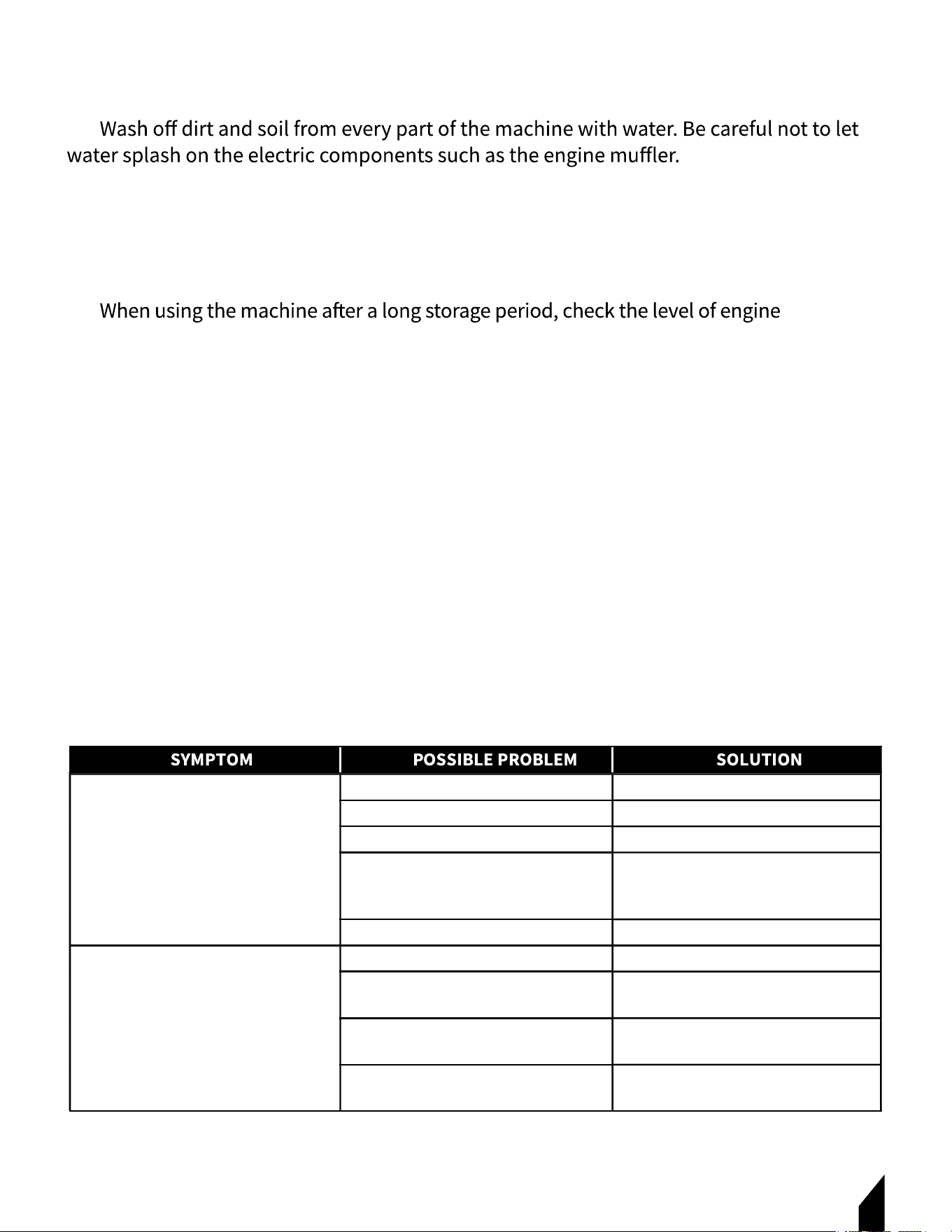
11. TROUBLESHOOTING
Clutch slips? Adjust or replace clutch.
V-belt slips?
Travel speed low and vibration weak.
Adjust or replace V-belt.
Excessive oil in vibrator? Fill to correct level.
Trouble in vibrator internals?
Wear/Damage of shock absorber? Replace shock absorber.
Bearing of roll is damaged? Replace bearing.
Push-Pull of compactor is heavy.
Check vibrator assembly for any
worn or defective parts, replace any
defective parts.
Water in the bearing of roll causing it
to rust?
Replace bearing. Make sure no water
gets in.
Strings or other obstructions coiled
around rotary parts?
Remove obstructions and clean.
Adjust.
Seal of both ends come in contact
with frames?

1720
SYMPTOM SOLUTIONPOSSIBLE PROBLEM
Spark plug bridging? Check gap, insulation or replace spark plug.
Carbon deposit on spark plug? Clean or replace spark plug.
Dif cult to start, fuel is available, but no spark at
spark plug.
Short circuit due to de cient spark plug
insulation?
Improper spark plug gap?
Check spark plug insulation, replace if worn.
Set to proper gap.
Spark plug is red? Check transistor ignition unit.
Spark plug is bluish white?
No spark present at tip of spark plug?
If insuf cient compression, repair or replace
engine. If injected air leaking, correct leak. If
carburetor jets clogged, clean carburetor.
No oil? Add oil as required.
Oil pressure alarm lamp blinks upon starting?
(if applicable)
Check automatic shutdown circuit, oil sensor.
(if applicable)
Check if transistor ignition unit is broken, and
replace defective unit. Check if voltage cord
cracked or broken and replace. Check if spark
plug is fouled and replace.
ON/OFF switch is shorted?
Dif cult to start, fuel is available, and spark is
present at the spark plug.
Check switch wiring, replace switch.
Replace ignition coil.Ignition coil defective?
Improper spark gap, points dirty? Set correct spark gap and clean points.
Condenser insulation worn or short circuiting? Replace condenser.
Spark plug wire broken or short circuiting? Replace defective spark plug wiring.
Wrong fuel type?
Flush fuel system, replace with correct type of
fuel.
Water or dust in fuel system? Flush fuel system.
Air cleaner dirty?
Dif cult to start, fuel is available, spark is
present and compression is normal.
Clean or replace air cleaner.
Choke open? Close choke.
Suction/exhaust valve stuck or protruded?
Dif cult to start, fuel is available, spark is
present and compression is low.
Reseat valves.
Piston ring and/or cylinder worn? Replace piston rings and/or piston.
Cylinder head and/or spark plug not tightened
properly?
Torque cylinder head bolts and spark plug.
Head gasket and/or spark plug gasket damaged? Replace head and spark plug gaskets.
No fuel in fuel tank? Fill with correct type of fuel.
No fuel present at carburetor.
Fuel cock does not open properly?
Fuel lter/lines clogged?
Fuel tank cap breather hole clogged?
Apply lubricant to loosen fuel cock lever,
replace if necessary.
Replace fuel lter.
Clean or replace fuel tank cap.
Air in fuel line? Bleed fuel line.

21
SYMPTOM SOLUTIONPOSSIBLE PROBLEM
Air cleaner dirty? Clean or replace air cleaner.
Weak in power, compression is proper and
does not mis re.
Improper level in carburetor? Check oat adjustment, rebuild carburetor.
Defective spark plug? Clean or replace spark plug.
Improper spark plug? Set to proper gap.
Water in fuel system?
Flush fuel system and replace with correct
type of fuel.
Weak in power, compression is proper but
mis res. Dirty spark plug? Clean or replace spark plug.
Replace ignition coil.Ignition coil defective?
Wrong type of fuel? Replace with correct type of fuel.
Engine overheats.
Cooling ns dirty? Clean cooling ns.
Intake air restricted?
Oil level too low or too high?
Clear intake of dirt and debris. Replace air
cleaner elements as necessary.
Adjust oil to proper level.
Rotational speed uctuates.
Governor adjusted incorrectly? Adjust governor.
Governor spring defective? Replace governor spring.
Fuel ow restricted? Check entire fuel system for leaks or clogs.
Recoil mechanism clogged with dust and dirt?
Recoil starter malfunctions. (if applicable)
Clean recoil assembly with soap and water.
Spiral spring loose? Replace spiral spring.
Starter malfunctions.
Loose, damaged wiring?
Ensure tight, clean connections on battery
and starter.
Battery insuf ciently charged? Recharge or replace battery.
Starter damaged or internally shorted? Replace starter.
Burns too much fuel.
Over-accumulation of exhaust products?
Wrong spark plug?
Check and clean valves. Check muf er and
replace if necessary.
Exhaust color is continuously white.
Lubricating oil is wrong viscosity?
Replace spark plug with manufacturer’s
suggested type.
Replace lubricating oil with correct viscosity.
Worn rings? Replace rings.
Air cleaner clogged?
Exhaust color is continuously black.
Clean or replace air cleaner.
Choke valve set to incorrect position? Adjust choke valve to correct position.
Replace carburetor or seal.
Carburetor defective, seal on carburetor
broken?
Adjust carburetor.
Poor carburetor adjustment, engine runs too
rich?
ON/OFF device not activated ON?
Will not start, no power with key ON.
(if applicable)
Battery disconnected or discharged?
Turn on ON/OFF device.
Check cable connections. Charge or replace
battery.
Ignition switch/wiring defective? Replace ignition switch. Check wiring.
1722
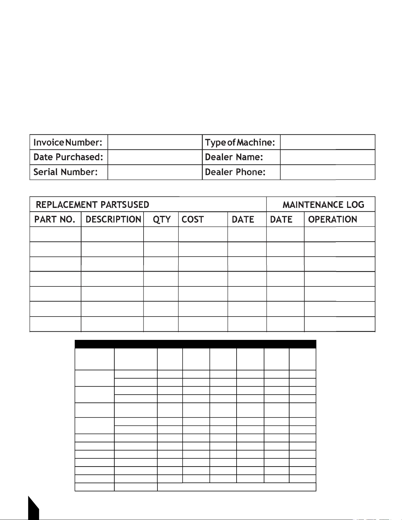
12. MAINTENANCE RECORD
TOMAHAWK® tools are assembled with care and will provide years of service when properly
maintained. Preventative maintenance and routine service are essential to the long life of
your quipment. Adhere to reading through this manual thoroughly. You will find that you can
do some of the regular maintenance yourself. However, when in need of parts or major
service, be sure to contact a TOMAHAWK® Technician. For your convenience we have
provided this space to record relevant data and maintenance schedule about your
TOMAHAWK® equipment.
Description (3) Operation
Engine Maintenance Schedule
Before
First
Month or
10 hrs
Every 3
Months or
25 hrs
Every 6
Months or
50 hrs
Every
Year or
100 hrs
Every 2
Years or
200 hrs
Engine Oil
CHECK X
CHANGE X
Air Cleaner
CHECK X
CHANGE X (1)
All Nuts and
Bolts
Re-tighten If
Necessary
X
CHECK-CLEAN
Spark Plug
X
REPLACE X
Cooling Fins CHECK X
Spark Arrester CLEAN X
Fuel Tank CLEAN X
Fuel Filter CHECK X
Idle Speed CHECK-ADJUST X (2)
CHECK-ADJUST X (2)Valve Clearance
Fuel lines CHECK Every 2 years (replace if necessary) (2)

23
13. EQUIPMENT WARRANTY
Your new TOMAHAWK® equipment is warranted to the original purchaser for a period of
against defects in design, materials and workmanship.
The following are not covered under the warranty:
13.1.1 Damage caused by abuse, misuse, dropping or other similar damage caused by or as
a result of failure to follow assembly, operation or user maintenance instructions.
13.1.2 Alterations, additions or repairs carried out by persons other than TOMAHAWK® or
their recognized agents.
13.1.3 Transportation or shipment costs to and from TOMAHAWK® or their recognized
agents, for repair or assessment against a warranty claim, on any machine.
13.1.4 Materials and/or labor costs to renew, repair or replace components due to fair
wear and tear.
13.1.5 TOMAHAWK® and/or their recognized agents, directors, employees or insurers will
with or by reason of or the inability to use the machine for any purpose.
Warranty Claims
Before submitting any warranty claim, you will need to register
your new TOMAHAWK® equipment through
www.tomahawk-power.com.
Follow the steps on page 3 or scan this QR codes to complete
all warranty claims should firstly be directed to TOMAHAWK®
through the online Service Request form found
at www.tomahawk-power.com/pages/service-request.
14. SERVICES CENTERS
Our service centers are equipped to handle your equipment maintenance and repair needs
support and genuine parts needed to keep your equipment running smoothly. All locations
are listed on the webpage https://tomahawk-power.com/pages/find-a-service-center.

24
Item #: TPC80H
5.5
HP
17
X
21 VIBRATORY
PLATE COMPACTOR
www.tomahawk-power.com
ALL MUSCLE.
PURE PERFORMANCE.
Great for safe compaction
of brick or stone patios.

25
POUND FOR POUND
THE HARDEST HITTING RAMMER
Achieve 100% Compaction Ratings on field density tests
Powered by Honda engines, Tomahawk Rammers are
Item #: TR68H
3,550
LBS/FT
3.6
HP
121
CC
TAMPING RAMMER
www.tomahawk-power.com

26
27
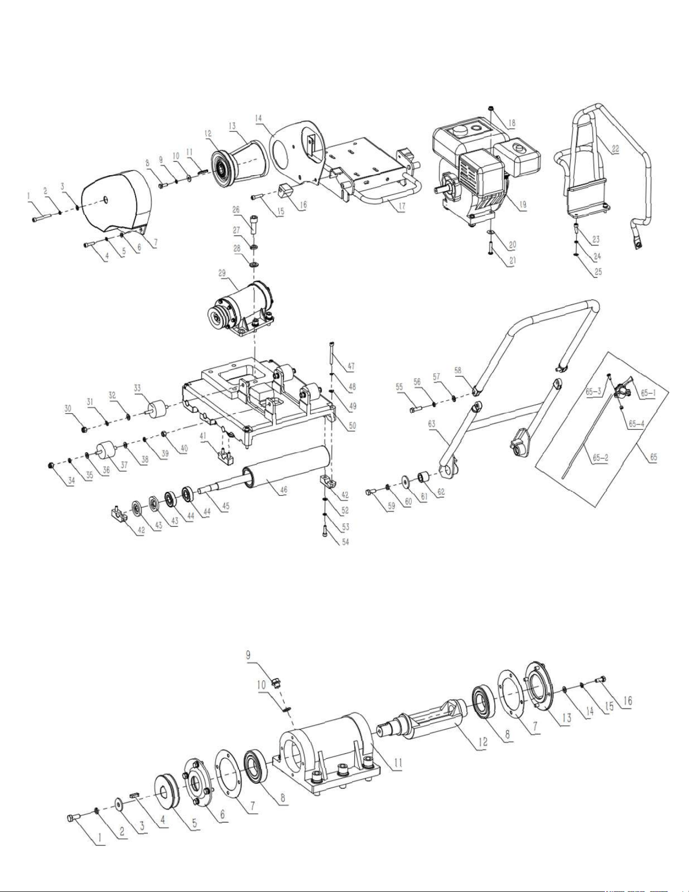
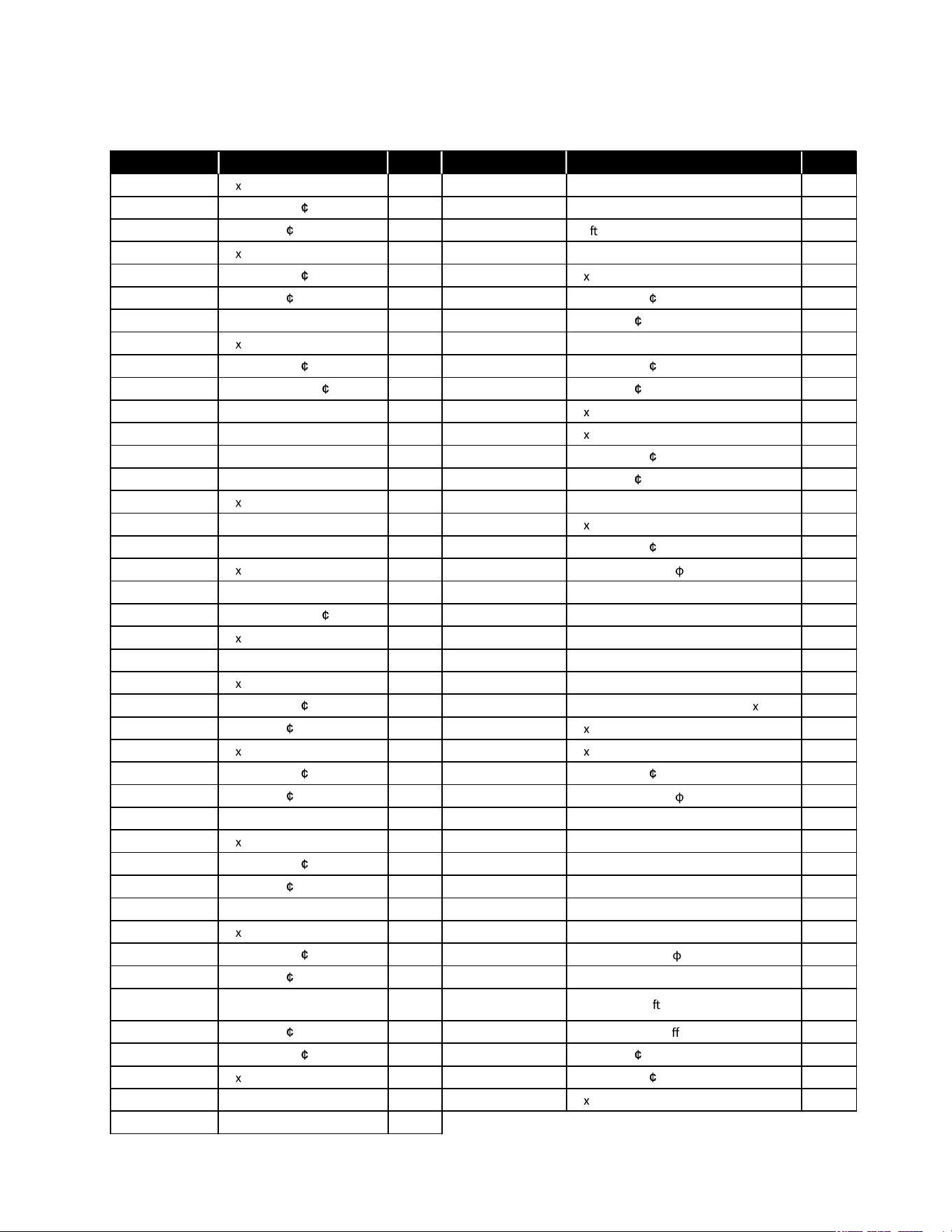
PARTS LIST
PART NO. DESCRIPTION QTY PART NO. DESCRIPTION
QTY
CNP80GL001 He socket bolt M8X65 1 CNP80GL043 Skeleton oil seal 20*52*7 16
CNP80GL002 Spring washer 8 1 CNP80GL044 Deep groove ball bearing 6304-2RS 16
CNP80GL003 Flat washer 8 1 CNP80GL045 Sha of roller 4
CNP80GL004 He socket bolt M8X30 1 CNP80GL046 Roller 4
CNP80GL005 Spring washer 8 1 CNP80GL047 He socket bolt M8X70 4
CNP80GL006 Flat washer 8 1 CNP80GL048 Spring washer 8 4
CNP80GL007 Belt cover 1 CNP80GL049 Flat washer 8 4
CNP80GL008 He bolt M8X25 1 CNP80GL050 Vibrating plate Assy 1
CNP80GL009 Spring washer 8 1 CNP80GL052 Spring washer 8 8
CNP80GL010 Bigger flat washer 8 1 CNP80GL053 Flat washer 8 8
CNP80GL011 Flat key 5*40 1 CNP80GL054 He socket bolt M8X30 8
CNP80GL012 Clutch Assy 1 CNP80GL055 He bolt M8X35 2
CNP80GL013 Betl A762 1 CNP80GL056 Spring washer 10 2
CNP80GL014 Dust-proof plate 1 CNP80GL057 Flat washer 10 2
CNP80GL015 He socket bolt M8X35 1 CNP80GL058 Upper half of handle 1
CNP80GL016 Shock absorber, handle 2 CNP80GL059 He bolt M12X25 2
CNP80GL017 Plate for engine mounting 8 CNP80GL060 Spring washer 12 2
CNP80GL018 He nut with flange M8 4 CNP80GL061 Biggest flat washer 12 2
CNP80GL019 Engine 1 CNP80GL062 Rubber coupling for handle 2
CNP80GL020 Bigger flat washer 8 4 CNP80GL063 Lower half of handle 1
CNP80GL021 He bolt M8X40 4 CNP80GL065 Throttle lever Assy 1
CNP80GL022 Protective frame 1 CNP80GL065-01 Throttle lever 1
CNP80GL023 He socket bolt M8X25 3 CNP80GL065-02 Throttle cable 1
CNP80GL024 Spring washer 8 3 CNP80GL065-03 Cross recessed pan head screw M6 16 2
CNP80GL025 Flat washer 8 3 CNP80GL065-04 He nut M6 2
CNP80GL026 He socket bolt M16X45 6 CNP80GL029-01 He bolt M10X25 1
CNP80GL027 Spring washer 16 6 CNP80GL029-02 Spring washer 10 1
CNP80GL028 Flat washer 16 6 CNP80GL029-03 Biggest flat washer 10 1
CNP80GL029 Vibrator Assy 1 CNP80GL029-04 Flat key 8*25 1
CNP80GL030 He locknut M10 4 CNP80GL029-05 Pulley, driven 1
CNP80GL031 Spring washer 10 1 CNP80GL029-06 Case cover for pulley 1
CNP80GL032 Flat washer 10 1 CNP80GL029-07 Paper cushion 2
CNP80GL033
S
h
o
c
k
a
b
s
o
r
b
e
r
w
i
t
h
l
o
n
g
e
r
s
c
r
e
w
b
a
s
e
p
l
a
t
e
1 CNP80GL029-08 Deep groove ball bearing 6209-2RZ 2
CNP80GL034 He locknut M10 3 CNP80GL029-09 Oil plug bolt M14X11 1
CNP80GL035 Spring washer 10 3 CNP80GL029-10 Aluminium washer 14 1
CNP80GL036 Flat washer 10 3 CNP80GL029-11 Vibrating case 1
CNP80GL037
S
h
o
c
k
a
b
s
o
r
b
e
r
w
i
t
h
n
o
r
m
a
l
screw, base plate
3 CNP80GL029-12 Ecc. Rotary sha 1
CNP80GL038 Flat washer 10 4 CNP80GL029-13 Case cover / shut-o 1
CNP80GL039 Spring washer 10 4 CNP80GL029-14 Flat washer 8 1
CNP80GL040 He locknut M10 4 CNP80GL029-15 Spring washer 8 1
CNP80GL041 Plate 6 CNP80GL029-16 He bolt M8X20 8
CNP80GL042 Plate for roller 2
Rammers
8 ft Hydraulic Steer, 35 HP Vanguard,
CVT Clutch, 180 RPM
10 ft Full Hydrostatic, 74 HP Hatz
Diesel
Part#:
TPT24H
TPT36H
TPT46H
Part#:
JXPT30T
Part#:
TRT46V
TRT60V
2 ft Edger, Honda GX160, 0-28
o
Blade Pitch
3 ft, Honda GX160/GX270, 0-28
o
Blade Pitch
4 ft, Honda GX270/GX390, 0-28
o
Blade Pitch
We’re here to help!
Email us at [email protected]
Forward Plate Compactors
Reverse Plate Compactors
Part#:
TR68H
JX60H
eJX60H
TVSA-H
eTVSA
Part#:
Part#:
TPC80H
Power Screeds
Porta-Trowels
Concrete Sprayers
Walk Behind Trowels
Ride on Trowels
Early Entry Saws
Part#:
6-16 ft Magnesium Blades
Honda GX35, Adjustable Handles
6-16 ft Magnesium Blades
36V/5 Ah Battery, Adjustable Handles
Part#:
TFS6H
TFS10H
Part#:
TCS6.5
6" Blade Diameter, Blade Compatibility,
Honda GX120
10" Blade Diameter, Self Propelled,
Blade Compatibility, Honda GX270/GX390
TPC85H
TPC90H
TPC170H
TPC100H
TPC400H
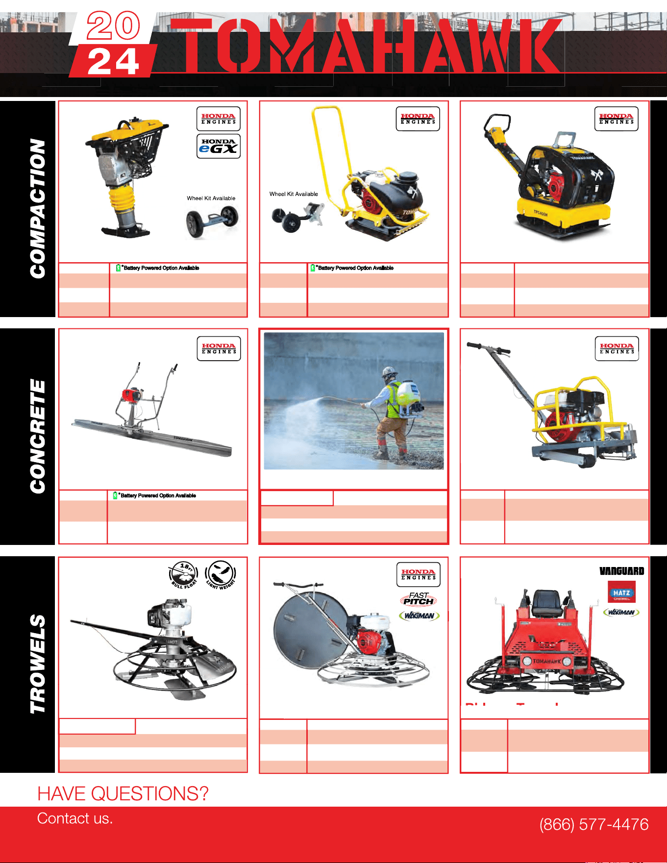
Equipment Guide
3,000 lbs/sq ft, Honda, 21”x17” Plate
3,200 lbs/sq ft, Honda, 23”x17” Plate
3,400 lbs/sq ft, Honda, 22”x20” Plate
3,500 lbs/sq ft, Honda, 19”×14” Plate
7,000 lbs/sq ft, Honda, 28”x20” Plate
11,690 lbs/sq ft, Honda, 32”x22” Plate
Lightweight at 40 lbs
Adjustable 18 ft Extension Bull Float Poles
30" Diameter, 4-Blade Assembly
Adjustable Blade Pitch from 0-28
o
Adjustable from 0-450 PSI
Handles 30% + Solids,1.8 HP 2 Stroke Motor,
24" Brass Wand 0.5 GPM, Fan Nozzle Included,
Spray 15,000 ft
2
in 10 Minutes
3,550 lbs/sq ft, Honda GX120
3,350 lbs/sq ft, Honda GX100
3,350 lbs/sq ft, Honda GXE2.0S
Items Listed Includes Combo Blades
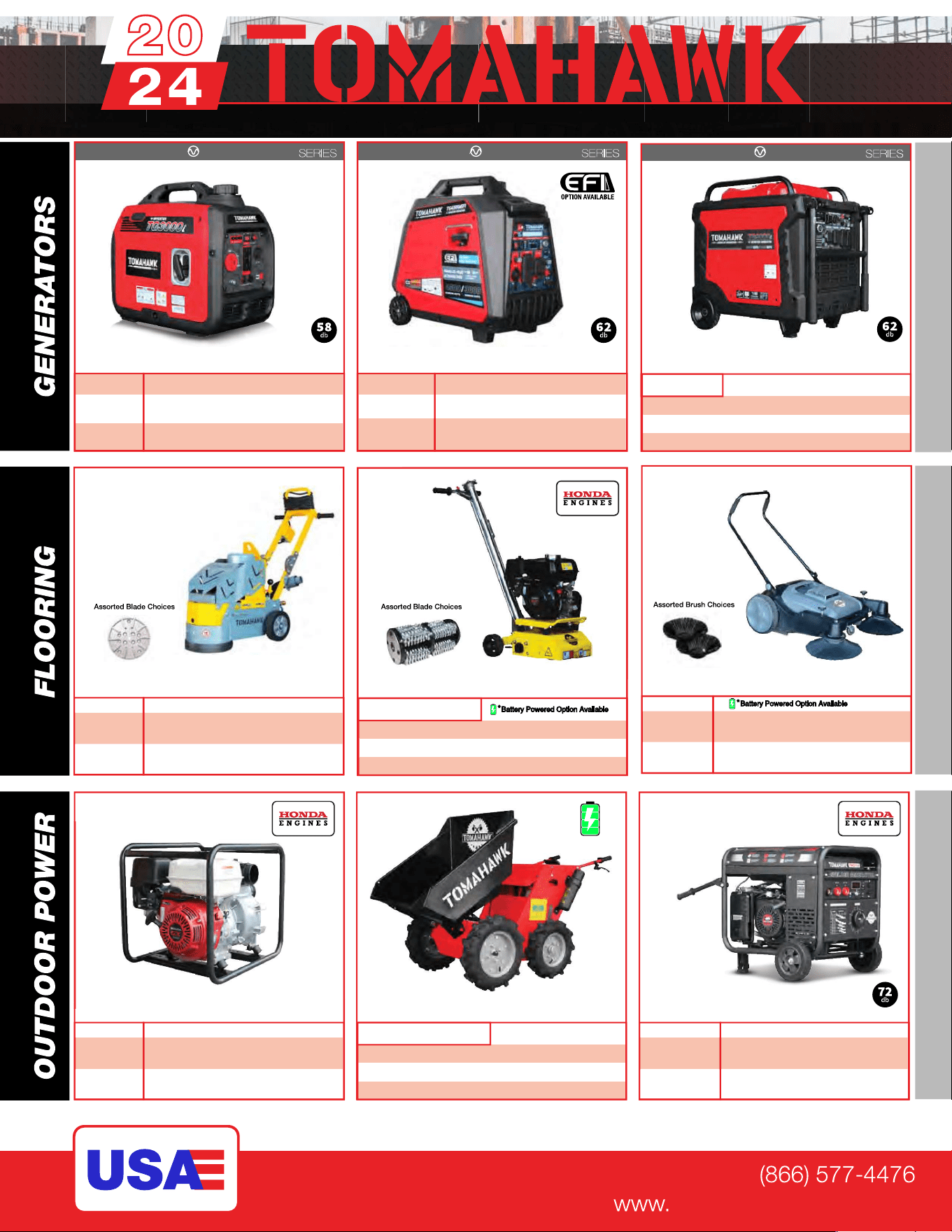
QUIET INVERTER
QUIET INVERTER
Welder GeneratorsPower Buggy
48V-20Ah Battery
Handles up to 8 cu ft or 660 lbs. Bucket Capacity
Hydraulic Bucket with 92
o
Tilt, 8 Hour Run Time
Snow Plow Attachment & Bucket Extender Available
Part#:
TGDR10
TSCP8
4,500 - 5,500 Watt Series
10,500 Watt Series
Concrete Scarifier
Floor Sweepers
Grinders and Scrapers
Part#:
TSCAR-8H
Trash Water Pumps
Part#:
TW3H
TW4H
3" Pump, Honda GX270, 375 GPM,
Elevation: 89ft, Suction: 25ft
4" Pump, Honda GX390, 581 GPM,
Elevation: 92ft, Suction: 26ft
QUIET INVERTER
tomahawk-power.com
ASSEMBLED IN THE
PARTS SOURCED GLOBALLY
TG2000i
TG3000i
2,000 - 3,300 Watt Series
Equipment Guide
10" Disc, 120V, 1/32" Per Pass,
11 AMP, 1.5 HP, 1,725 RPM
8" Blade, 120V, 11 AMP, 3/4 HP,
1,725 RPM, Carpet & Tile Remover
Honda GX160 Engine, Scarifies 350 - 500ft
2
/hr
OSHA Compliant Vacuum Port
8" Carbide Tungsten Drum Kit, 1/8" Per Pass
38" Working Width, Triple Broom
System, 14.5 Gallon
30" Working Width, Battery Powered
Triple Broom System, 13.5 Gallon
120 Amp Welder, 60% Duty Cycle,
2000w, Includes Wheel Kit
210 Amp Welder, 60% Duty Cycle,
2000w, Includes Wheel Ki
t
4,500w Max
/
3,800w Rated
5,500w Max / 5,000w Rated, 120/220V
Run Time 8 Hrs @ 50% Load
CARB Compliant, GFCI
TG4500i
TG5500i
10,500w Max
/
8,500w Rated
Voltage Selector, 120/220V
Run Time 14.5hrs @ 25% Load
CARB Compliant, GFCI, CO Detector
TG9000i
2,200w Max
/
2,000w Rated
3,300w Max
/
3,000w Rated,
120/220V, 30 AMP Twist Lock
Run Time 8 Hrs @ 50% Load
CARB Compliant, GFCI 120v
6010-7024 Rods Compatible
Part#: TBUGGY300e
Part#:
TWG120A
TWG210A
Part#:
TOS38
eTOS30

TOMAHAWK®, LLC
San Diego, CA
Sales Support
(866) 577-4476
Equipment Support
(866) 577-4476
www.tomahawk-power.com
Tomahawk understands to keep a job-site running smoothly the proper equipment and
spare parts are needed at the drop of a hat. With same day shipping and faster
delivery times, count on Tomahawk to keep you powered throughout the day! With
long lasting parts and engines, Tomahawk equipment will be the star of your fleet for
years to come. Visit www.tomahawk-power.com to get started today!
Power Your World
FACEBOOK
facebook.com/TomahawkPowerUSA
YOUTUBE
youtube.com/TomahawkPower
INSTAGRAM
@tomahawkpower
